Article

A UAV-GPR Fusion Approach for the Characterization of a Quarry Excavation Area in Falconara Albanese, Southern Italy

by
Annamaria Saponaro
*,
Giovanni Dipierro
,
Emanuele Cannella
,
Antonio Panarese
,
Angelo Maurizio Galiano
and
Alessandro Massaro
Dyrecta Lab, IT Research Laboratory, Via Vescovo Simplicio 45, 70014 Conversano, Italy
*
Author to whom correspondence should be addressed.
Drones 2021, 5(2), 40; https://doi.org/10.3390/drones5020040
Submission received: 13 April 2021 / Revised: 15 May 2021 / Accepted: 17 May 2021 / Published: 18 May 2021

Abstract

:
The characterization of a quarry site which is suitable for railway ballast aggregate production represents a big challenge for the mining industry. The knowledge of structural discontinuities within local geological materials is fundamental to guide mining operations, optimize investments, and guarantee quarry security. This research work presents an innovative methodology for the subsurface investigation of a quarry excavation area down to a depth of about 50 m in Falconara Albanese, Calabria, Italy. The proposed methodological approach incorporates photogrammetry, drone technology, and GPR data acquisition and processing. Photogrammetry represents the first step for obtaining a 3D topographical model reconstruction of the whole quarry, helping to detail the acquisition approach and properly plan the subsequent drone survey. In particular, two 120 MHz antennas have been mounted on the drone and two profiles have been acquired above and across the quarry. Results show the presence of fractured material and demonstrate the applicability of the method for identification of areas that are more suitable for railway ballast production. The presented method is therefore capable of detecting subsurficial fractures at a quarry site by means of a relatively fast and cost-effective procedure. Results are achieved within the framework of an industry project.

1. Introduction

The identification of optimal site conditions for railway ballast production is far from being trivial. Railway ballast aggregate must satisfy a few requirements in order to be used for railway track support. In particular, it has to withstand a range of forces, such as large cyclic loadings or vibrations of varying frequencies and intensities. Moreover, this material has to resist chemical actions linked to repeated wetting and drying cycles determining crystallization of rain-dissolved soluble salts [1]. Therefore, during ballast production it is fundamental to control the particle shape, the grains surface/texture, their gradation, and degree of purity. On the whole, these features are responsible for providing high stability to the ballast layer as well as lateral resistance to the lateral ballast flow.
The reliability of quarry-site investigations hangs on several factors and actions. Determining the most suitable materials and evaluating the degree of fracturing represent fundamental steps for a proper site assessment. On the other hand, the level of profitability of a quarry depends on specific properties, such as rock texture and the size of the blocks [2]. In particular, recent studies indicate the main factors for quarry site identification and characterization [3]: (1) type of rock, (2) rock weathering grade, (3) presence of geological structures relating to jointing and fracturing, (4) thickness of overburden at quarry site, (5) land-use distribution, and (6) accessibility of quarry site. Therefore, actions with the aim of retrieving the main tectonic structures and deformation style at a quarry site are necessary to identify optimal exploitation conditions [4].
In line with this, it is well recognized that the rock type specifies the rock’s physical and mechanical properties, and its suitability for a specific engineering function [5]. While the weathering grade refers to rock rippability, which in turn controls the excavation method, the presence of rock discontinuities gives insights about the feasibility of producing large size blocks, an aspect that is particularly relevant for extraction of ornamental granite [6]. Together with this, the knowledge of available weathered rock at a quarry location may support economic feasibility studies and consequently aid in planning an optimal mining operation.
Among geophysical prospecting techniques, ground penetrating radar (GPR) is an electromagnetic method based on the use of high-frequency (10 MHz–2.5 GHz) electromagnetic waves to get high resolution images of shallow geologic features, i.e., faults and fractures. A detailed description of the method can be found in [7]. Compared to drilling prospecting techniques, the choice of indirect geophysical prospecting methods such as GPR guarantees repeatability and rapidity [8].
The reliability of GPR as a non-invasive, fast-applicable and accurate geophysical prospection method for detecting subsurface anomalies has already been underlined in many studies. The first GPR experiments for geological engineering applications highlighted that such a technique could solve a wide range of engineering and environmental problems. In particular, GPR was already adopted to detect solid buried waste [9,10] to investigate internal rock structures [11,12] and to image structural details of subhorizontal fractures on the floor of a gneiss quarry [13]. Moreover, GPR data have been acquired on vertical cliff faces through a conventional common-midpoint (CMP) survey for delineating fractures in limestone cliffs [14]. Specifically, this nondestructive method was extensively applied for detecting and modeling rock fractures with the aim of optimizing the extraction of ornamental stone deposits in quarries [15]. Besides, this GPR was successfully used for quality assessment of natural stones to evaluate the presence of fractures and physical defects [16]. Despite a range of GPR application examples, there has been an emphasis on its powerful application in the high-resolution definition of fractures in bedrocks [7].
There are a few problems relating to the use of GPR for two- and three-dimensional structure identification. First of all, a comprehensive interpretation of radargrams may be limited due to low data quality [17] and interference phenomena originating from nearby sources. Secondly, proper GPR data processing is necessary to retrieve reliable subsurface images and avoid data distortions and misinterpretations [18]. Additionally, one of the main difficulties of GPR application is the calculation of the dielectric constant characterizing the specific rock layer in which electromagnetic waves propagate: the more accurate the dielectric constant, the more precise the detection and the morphological characterization of anomalies at true investigation depth [19]. This important physical parameter is not constant but varies within the rock both on microscopic and macroscopic scales. Hence, it is appropriate to calculate the bulk dielectric constant starting from the average propagation velocity. This parameter can be estimated by fitting different hyperbolic diffractions linked to fractures found at various depths [20]. Another limitation of the GPR technique is the instrumental frequency of antennas, which influences the depth of investigation. Accordingly, a higher instrumental frequency allows for a more detailed near-surface characterization, while lower frequency antennas allow for a deeper scanning at lower spatial resolution. Therefore, the reliability of GPR studies relies upon the trade-off between instrumental frequencies and the depth of investigation.
Successful examples of GPR applications for fracture identification in different mining environments have already been shown in literature in limestone [20], marble [21], and underground marble mine [22] contexts. Nevertheless, the identification of near-surface discontinuities at quarry sites by means of GPR antennas represents an ongoing topic to be encouraged [23].
Moreover, in harsh topographic environments the application of the GPR method is not easily achievable. This limitation can be overcome by mounting the GPR on unmanned aerial vehicles (UAVs), commonly known as drones.
UAVs equipped with GPRs are well suited to traverse areas inaccessible to humans, such as minefields [24]. Such prospecting technologies have recently been receiving attention both for military purposes and civil engineering applications, i.e., when applied for surveillance, diagnostics, and real time monitoring purposes in the context of natural hazards [25,26]. The first remarkable examples of the application of UAVs in quarry contexts can be found in [27,28] and, more recently, in [29]. In this work, the technology was adopted for monitoring purposes and analyzing the structural-geological setting of a quarry, with the objective of identifying unstable zones. Further scientific contributions have shown the potential of UAV-based photogrammetry for accurately mapping an open pit quarry [30] and the high-resolution reconstruction of a quarry’s topography [31,32]. Furthermore, in recent years UAV technologies have been successfully used for environmental applications, allowing for the acquisition of high-resolution remote sensing data and photogrammetric reconstruction in a flexible way [33,34].
The integration of a GPR system mounted onboard an UAV represents a promising research direction in that it creates a mobile automation solution for a wide range of geoengineering challenges. A few applications of UAV GPR systems can be found in studies aiming at identifying buried objects without being in contact with the soil [35] and performing non-destructive testing activities [36,37]. However, UAV radar systems are limited by the bias affecting UAV height [25] and their energy-limited nature, which influences their flight time [38].
Nevertheless, UAV technology offers the opportunity to inspect wide areas by moving around an arbitrary, predefined trajectory at different heights, making detailed geophysical surveys possible. Furthermore, compared to traditional survey methods, the drone-based approach is less time-consuming, especially when an extended area needs to be surveyed [20].
With these premises, the main objective of this work is to characterize a quarry excavation area, in Falconara Albanese, Southern Italy. The study area, described in detail in Section 2.1 was investigated by means of the UAV GPR technology supported by the photogrammetric technique, where the photogrammetry represents the first step for defining the acquisition approach and properly planning the subsequent drone survey. In this way, after defining UAV flight paths, experimental activities were carried out across the quarry excavation area by means of a GPR system. Acquired GPR data were then processed and analyzed. The interpretation of results provides insights about the overall degree of fractures characterizing the quarry excavation area, which in turn allows for the identification of areas with the potential for quarry exploitation (Figure 1).
Considering the objective of this study, we found a trade-off between penetration depth and resolution by focusing on an instrumental frequency range between 50 and 300 MHz. In this way, it is possible to detect subsurface high fractured rocks, a meaningful indicator for the extraction of suitable material for railway ballast production. Furthermore, the GPR survey is supported by geological and lithological data providing additional information about the local geological setting [39].
The presented work lays the foundations for the recognition of the most suitable methodology to be applied in the future to new quarry sites. It demonstrates the feasibility of using a UAV GPR system to successfully detect subsurficial fractures and discontinuities in quarry sites characterized by ongoing railway ballast production activities. In this way, it is possible to support railway industry operations in the process of quarry site characterization by means of a fast-applicable, reliable, and cost-efficient geophysical prospecting technique.

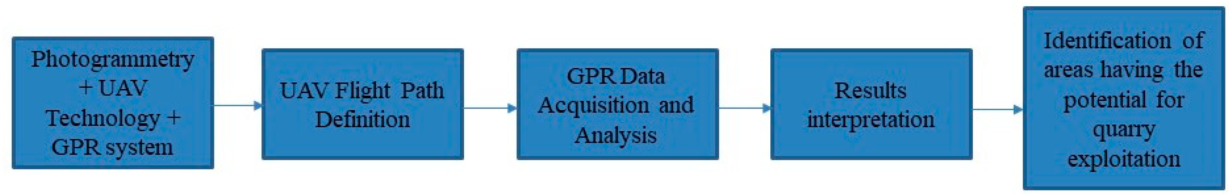
2. Materials and Methods
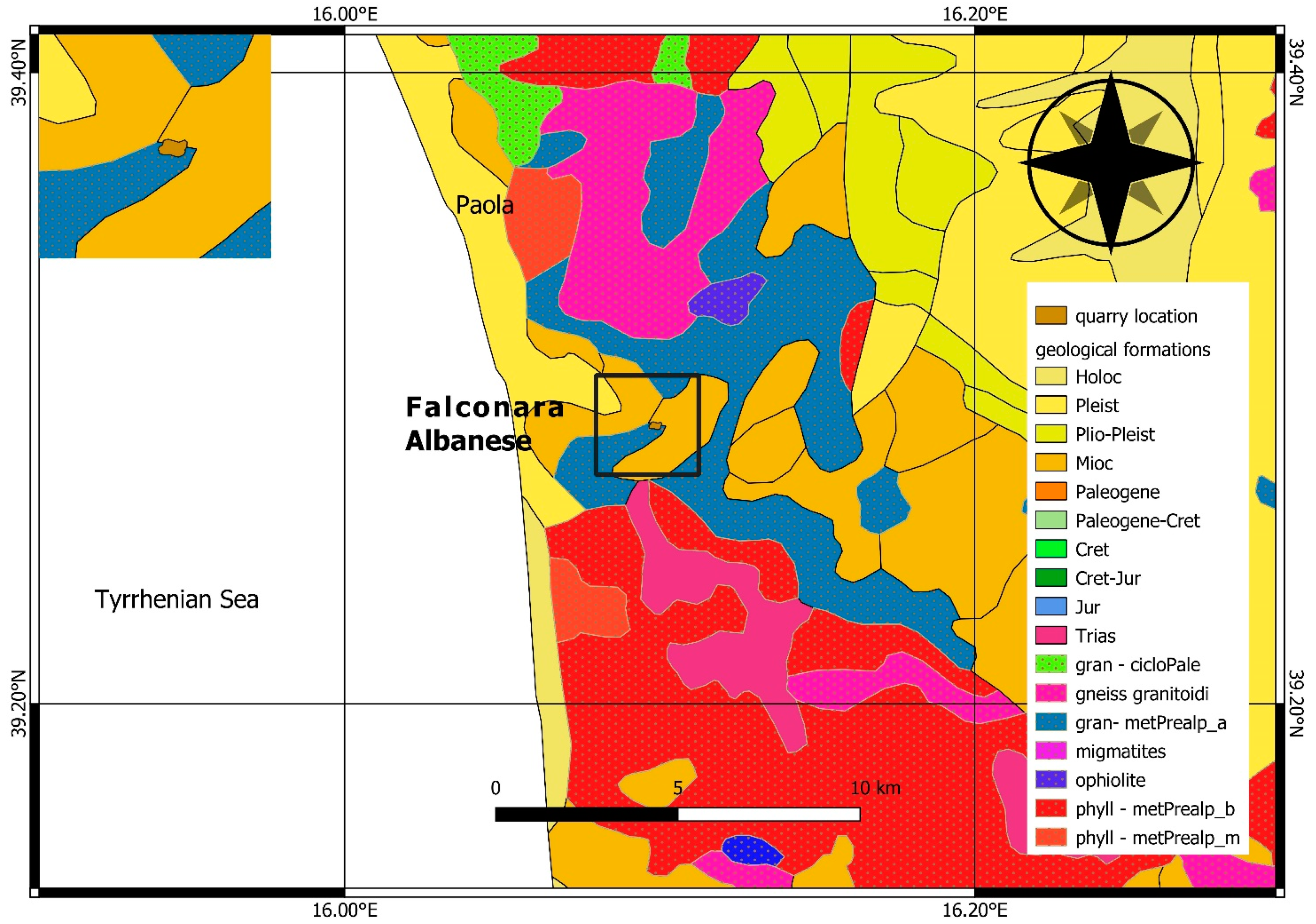
In this section, details about the study area hosting the experimental activities and the adopted methods are provided. Specifically, Section 2.1 contains an extensive description of the study area, including information about local geological formations. Moreover, a 3D topographical reconstruction of the quarry is presented, serving as a basis for the subsequent drone GPR analysis. In Section 2.2, details about data acquisition and processing operations are reported.

2.1. Study Area

The study area belongs to the municipal territory of Falconara Albanese (CZ, Italy), rising from elevations of 650 m a.s.l. on a gentle slope in the proximity of the municipal territories of Paola, Marano Principato, Fiumefreddo Bruzio, and S. Lucido.
The quarry is located about 4 km inland (airline distance) from the Tyrrhenian sea coast (Figure 2).The area is geologically diverse and complex, with formation belonging to three orogenic phases, from the lower Paleozoic to the Holocene [40]. The region belongs to the Calabrian Arc, an orogenic structure characterized by a number of tectonic units derived from original paleo-geographic domains of the Tethys [41], including remnants of the Alpine-Betic back-thrust belt superimposed onto the Apennine Chain during the opening of the Tyrrhenian back-arc basic [42].
From a geodynamic perspective, the area is ruled by active crustal deformation as a result of subduction of the Ionian lithosphere beneath the Calabrian Arc. The Calabrian Arc constitutes a composite subduction complex, which is segmented longitudinally into two different lobes having different structural styles, deformation rates, and basal detachment depths [43]. The entire region is, therefore, dominated by fractures relating to different local responses to regional movements. Besides, the combined presence of both excavation and collection districts at the quarry site provides an additional level of topographical complexity.
Based on published cartography and literature, it is possible to recognize a variety of geological materials of the metamorphic type, such as granulites, gneiss with marble, amphibolites, and high grade alpine metamorphites [39]. The geological setting is completed by the presence of Mesozoic carbonate successions, portions of the Paleozoic basement made up of granite plutons, and a variety of metamorphic rocks. The whole spatial distribution of local geological units is enclosed in Figure 2. As it can be seen, geological formations are classified according to the era and specifically into: Paleozoic, Mesozoic, and Cenozoic. In particular, Mesozoic rocks are further classified into Triassic, Jurassic, Cretaceous-Jurassic, Cretaceous, and Paleogene-Cretaceous, based on the system they belong to; Cenozoic rocks can be further distinguished according to their epoch into Holocene, Pleistocene, Plio-Pleistocene, and Miocene. The area is also characterized by the presence of granite formations, as shown in Figure 2.
The analysis of outcropping geological formations in the region reveals the presence of rock types particularly suitable for ballast aggregation. Previous studies [3] have indicated that the following rock types are desired for quarry sites: granite, basalt, rhyolite, andesite, diorite, and well-cemented sedimentary rocks. In line with this, the presence of granulites (prealpine) and subsequential calcarenite (Miocene) characterizes the entire quarry district, as can be seen from Figure 2, confirming the area suitability as a quarry site.
A more comprehensive analysis of the physical characteristics of local rocks reveals the prevalence of the gneiss and mica schists rock types [44]. Gneiss shows a poorly developed cleavage while schists are dominated by coarse grained foliation and by the presence of elongated minerals. In particular, the mica schists represent foliated metamorphic rocks having a well-defined schistosity, a lamellar crystallographic habit, and the predominance (more than 50%) of biotite and muscovite. Both schist and gneiss refer to high-grade metamorphisms; while schists have the tendency to split into layers, gneiss are outlined by a typical gneissic banding, which is due to the effect of high temperature and high pressure during the process of rock formation.
To enhance the geological characterization, the quarry excavation area was preliminarily studied by carrying out a 3D topographical model reconstruction of the quarry. The reconstruction was achieved starting from pictures obtained from the image acquisition system mounted onboard a Phantom RTK drone. The drone flight was carried out through a grid acquisition pattern, covering the entire quarry, at an altitude of 70 m above ground level. The acquired pictures were processed by means of a photogrammetric open source software, i.e., MeshRoom. Pictures of the quarry 3D model are shown in Figure 3. The analysis of the 3D model was useful to obtain knowledge about the elevation within the quarry site and thus optimize the acquisition patterns of the GPR drone. The picture information is available from the enclosed metadata, i.e., the focal length and GPS data [45].

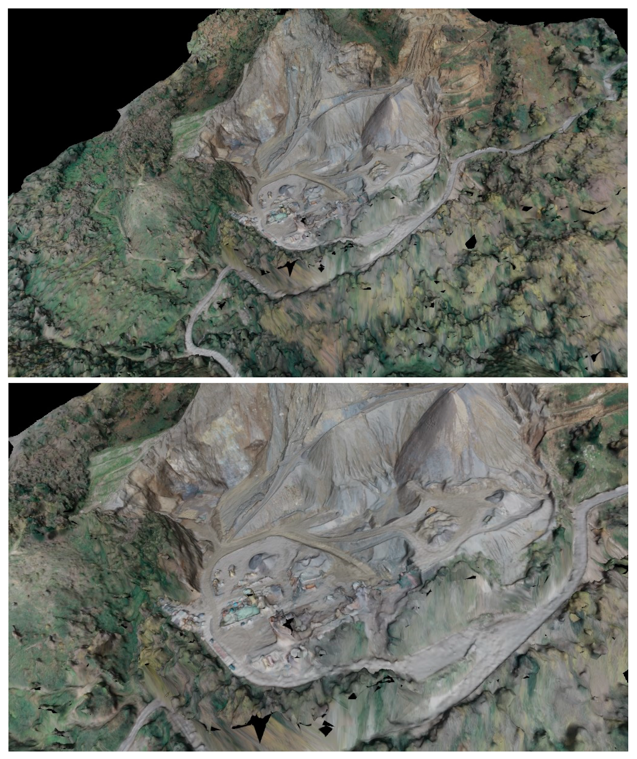
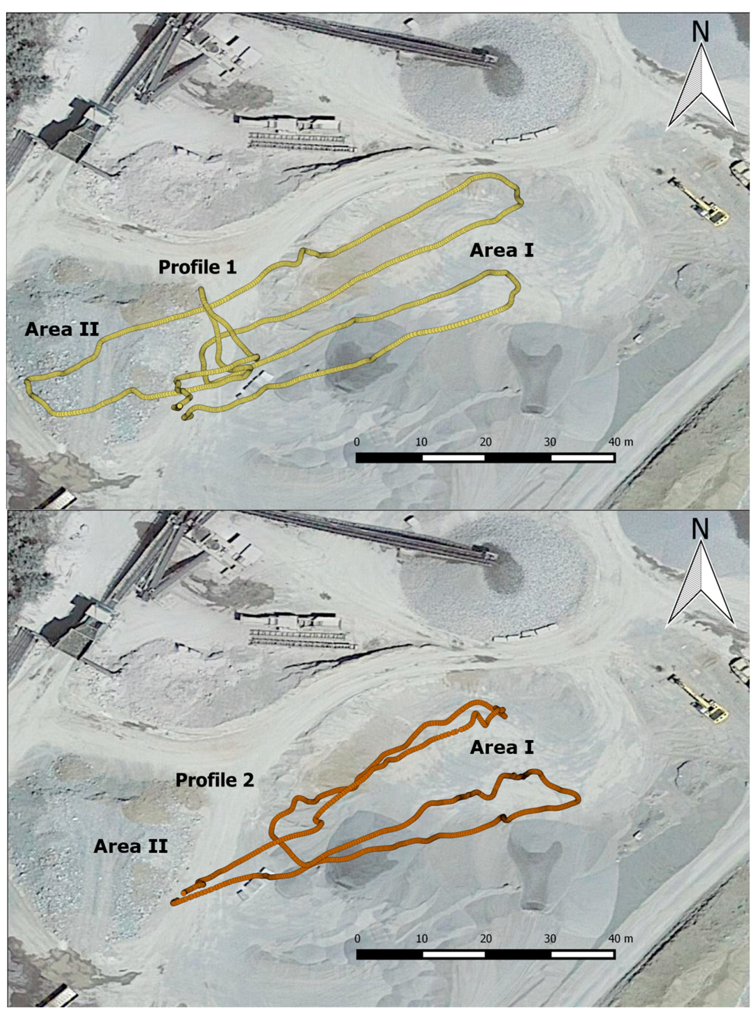
2.2. Data Acquisition and Processing

The survey was carried out by means of a COBRA Plug-in SE-150 monostatic antenna mounted on a DJI Matrice 600 Pro drone. In a monostatic configuration, transmitter and receiver are assumed to be at the same position. The antenna is characterized by a central frequency of 124 MHz and a bandwidth of 260 MHz. The antenna configuration allows us to investigate the subsurface structure with a vertical resolution of 27 cm and a penetration depth up to 40 m assuming a granitic substratum (relative dielectric constant equal to 5). A ground station was prepared in order to control acquisition operations. The data acquisition system was composed by a plug-in GPR-system and a wireless unit for real time sampling in 32 bit. A data logger was mounted on the drone allowing for GPR data logging and instrument controlling from the ground station (Figure 4). The drone was equipped with an automatic terrain following option for altitude detection with high precision on low elevation. After the initial takeoff and before the final landing, the flight height was kept constant at an average value of 6 m. Additional details about the UAV survey are shown in Table 1, where information about trace number, dimensions of movements, geographic coordinates and altitude is provided. In particular, the following variables are included: “trace”, “roll”, “pitch”, “yaw”, “latitude”, “longitude”, and “altitude”, with trace referring to trace number, roll, pitch and yaw values representing rotation angles with respect to x, y, and z axes, and latitude and longitude indicating geographic coordinates.
Cobra DAQ data acquisition software (v0.8.30 build 0) was used for GPR data acquisition, by setting the Bluetooth technology for signal ringing reduction. Four survey profiles were then recorded using constant offset between transmitter and receiver antennas. Data were acquired with a sampling interval of 3.125 ns and 512 samples per trace over a time window of 800 ns.
Data were post-processed using PRISM processing software (RadarTeam, v2.59). A number of filtering operations were applied to filter out from the data signal components having frequencies outside the bandwidth of the GPR system, hence enhancing the signal-to-noise ratio. Specifically, background removal was used to take out background influence, i.e., direct signal coming from the transmitter antenna, as well as to reduce the magnitude of ringing and horizontal banding artifacts throughout the whole signal [46]. A very important filter procedure in GPR data processing is band-pass filter. The band-pass filter is composed of two filters, namely the high-pass and the low-pass filter. The first one applies a cut-off to low frequency components from the whole frequency spectrum of a single trace, allowing for the removal of both ground-wave and other sources of environmental noise. On the other hand, the low-pass filter applies a cut-off to high frequency components from the frequency spectrum of each trace, usually related to additional electromagnetic interferences [18]. Band-pass filters in the range of frequencies between 3 and 309 MHz were chosen to highlight those signal frequencies within the instrument’s bandwidth where most of energy is located, removing the influence of high and low frequency-noise [46]. FK-filtering was carried out assuming a powering factor of 1.3 in order to remove the effect of lateral reflections from the quarry and properly locate subsurface dipping reflectors [6]. A moving average filter (5 trace-window) was applied to horizontally smooth the profile and, hence, facilitate subsequent results interpretation. The electromagnetic wave generated by the GPR is typically characterized by attenuation phenomena during its propagation through a medium. Compared to seismic waves, electromagnetic waves are characterized by a faster amplitude decay of the signal with depth [18]. As part of the data processing procedure, time-varying gains were introduced to compensate for signal exponential attenuation with depth, due to absorption, spherical divergence, and scattering phenomena [46]. Topographic correction was also applied in order to reconstruct a GPR profile as close as possible to the local relief. The conversion from time to depth domain was achieved by considering a radar velocity of 0.135 m/ns. The propagation of electromagnetic waves in the subsurface is related to the dielectric constant k by the relation v = c / k , where c represents the velocity of electromagnetic wave in free space, which is about 0.3 m/ns. For granite bedrock, the dielectric constant may vary from 5 to 8 [47].
Time-depth conversion was performed by using a relative dielectric constant of 5, corresponding to a wave velocity of 0.135 m/ns, based on the assumption that subsurficial materials are mostly made of dry granite (Table 2 [48]). Moreover, in order to highlight the energy content of the signal and retrieve instantaneous amplitude, Hilbert transform was used [49].

3. Results

Out of the four GPR recordings, we chose to present only two of them for further data processing. During the experiments there were some connection and power supply difficulties affecting initial survey operations, making a few recordings insufficient to provide insight about interior quarry districts. This issue prevented us from making use of all recordings. The two selected profiles were recorded along two track segments, as shown in Figure 5. The GPR surveyed area is characterized by an excavated district (Area I), from where materials were extracted, and a flat and convex zone (Area II), corresponding to the railway ballast collection district. The two districts are separated by a road crossing the quarry, which serves as a transport route for materials to be processed. In Figure 5, the two flight trajectories of acquired profiles, together with surveyed quarry districts, are shown.
GPR profiles were post-processed as described in Section 2.2. Profile 1 presents a 358.7 m-long profile for 1461 total traces, while profile 2 is a 263.6 m long profile for 1273 total traces.
Both profiles were interpreted in order to identify the meaning associated with the presence of discontinuities. In order to facilitate the interpretation of the radargrams, a few of the most commonly recognized features of GPR profiles are summarized and shown in the following scheme (Figure 6). A detailed overview of results interpretation and implications is provided in Section 4.

4. Discussions

Interpreted GPR profiles are presented in Figure 7.
Along the whole of profile 1 (top panel in Figure 7), the position of the first reflectors is related to the ground slope. Between distance coordinates of 20 and 115 m, the radargram shows the signal coming from the inner region of the excavated area (a). Between 8 and 13 m of depth, one can observe irregular reflectors that could be related to the contact between near-surface weathered fresh granite (altered material due to excavation procedures) and the unaltered granite below (b). In this region, at a depth of about 32 m, reflectors parallel to the topography can be noticed. These reflectors might indicate the separation between fractured material and underneath homogeneous granite (c). In the region of distance coordinates between 115 and 150 m, first reflectors associated with superficial granite are located at a depth of about 4 m. This evidence might suggest that the signal is actually coming from the region where the road is located. Importantly, the presence of weak reflectors constituting a V-shaped structure (dashed red lines) can be observed below the road district (d). The region between the location of first reflectors and the location of the V-shaped reflector is characterized by the absence of reflections. This evidence suggests the existence of homogeneous granite without any fracture, which extends to a relatively large depth. By comparing depth and structure of reflectors in the excavated district with those coming from the road region, we observe that the quarry excavation design follows subsurficial fractures. In this way, it can be assumed that the excavation path was specifically designed in such a way as to exploit the presence of fractures, with the aim of minimizing ballast production costs. An extended area with high energy in the electromagnetic signal can be seen at about 25 m of depth, between 160 and 220 m (e). These reflectors could be related to the presence of discontinuities in the subsurface. Additionally, a region without any reflectors can be identified between 250 and 325 m coordinates along the traces. Finally, the presence of a series of hyperboles between 310 and 360 m coordinates and about 20 and 30 m depth can be observed. This might indicate the presence of a point object (f).
Along profile 2 (bottom panel in Figure 7), it is possible to recognize the presence of irregular reflectors within the first 7 m of depth, corresponding to an extremely fractured and weathered granitic substratum layer (a). These reflectors are hence related to the corresponding contrast in electromagnetic properties of media in which waves propagate, i.e., air and altered granite. Scatter zones that typically characterize fractures are responsible for signal reflection phenomena; this element is quite well evident within the first 15 m of depth (b). According to field observations, the quarry area is overall ruled by the presence of fractured and altered materials at near-surface level, therefore confirming the high degree of surficial fracturing.
A relatively large area with high energy in electromagnetics signal can be seen at about 25 m depth, between 160 and 220 m (c). These reflectors could be linked to the presence of discontinuities and fractures in the subsurface, where the relatively large extension of the zone is probably related to the presence of sub-horizontal fractures filled with water. These water-filled fractures would determine a large contrast in the dielectric constant and, in turn, a large amplitude in the signal. This observation is supported by the fact that the geographic area belongs to the Malpertuso creek basin [50]. A similar structure might be responsible for the presence of relatively high energy reflectors on the 2-D section at about 30 m depth, between 100 and 120 m (d).
At about 30 m of depth, a weak reflector extending for almost the entire length of the 2-D section (black dotted line) can be observed. This GPR signal could be associated with the contact between fractured material and underlying basement host material. Below the depth of 30 m, the profile is characterized by the absence of any reflections, confirming the presence of homogenous granitic rock (e). This observation is consistent with the regional setting of the entire region, where the crystalline basement represents the main geological formation [51]. The goodness of this observation is further supported by the use of an antenna having a central frequency of 124 MHz, which ensures a penetration depth of about 50 m in the granitic substratum.
To be noted is also the presence of sub-vertical structures at about 100 m and 180 m (black lines), whose inner regions are characterized by absence of reflections, due to attenuation phenomena affecting electromagnetic waves during their propagation through altered materials [6]. Considering the regional geological setting of the area, the presence of dike-structures filling large fractures in massive rocks cannot be excluded.
The energy content of GPR signals is shown in Figure 8, for profile 1 and 2, respectively. These sections indicate the reflection energy associated with electromagnetic waves, where dark red corresponds to high energy level, while green indicates a low energy content.
As can be seen, it is possible to identify the presence of both near-surface fractured materials and a subsurficial high energy zone. This evidence, in line with what was previously shown [11,49], confirms the connection between the presence of fractures and high energy signal reflections. Below the depth of 45 m, a homogenous green area can be observed, corresponding to the granitic unaltered material.
The authors are aware of the critical role of the dielectric constant in GPR data interpretation. However, the choice of literature values for dielectric constant is part of the authors’ strategy to present a methodological approach to detect subsurface fractures under the limited conditions characterizing a quarry excavation area. In addition, the chosen value of dielectric constant corresponds to the average value among literature values associated with different degrees of altered/fractured granite [52], something that approximates the site conditions hereby addressed.
With regard to energy content, it should be noticed that a large contrast in dielectric constant clearly results in a high signal amplitude. The presence of water filled structures might be the reason for a considerable signal amplitude increase. For this reason, although only a single value of dielectric contrast was used in experimental results, we interpret the results as strongly affected by the presence of water filled structures.
As far as the resolution is concerned, the adopted instrument guarantees a vertical resolution of about 27 cm. According to the theory of thin beds [53], it is possible to detect reflections corresponding to fractures having thinner apertures, provided that these structures are separated by a distance equal to the vertical resolution. These thinner structures can generate a contrast of electromagnetic impedance due to interferences of down- and upward waves bouncing within the thin layer.
Moreover, GPR velocity models often incorporate sources of error that commonly affect the accuracy and precision of a velocity estimate [54]. Accordingly, the application of additional geophysical prospecting techniques, such as active seismic and electrical resistivity tomography, is usually recommended to further validate GPR results. However, due to the particular location of the hereby presented study case, constraining data interpretation with direct data was not achievable. Nevertheless, the analysis of in-situ rock samples was used to support our results interpretation. Based on in-situ observations, we confirm the presence of metamorphosed granitic rocks characterized by a moderate level of weathering and alteration (Figure 9). Considering the abundance of compacted opaque minerals surrounded by very fine-grained ground mass characterizing these rocks, it is possible to confirm the good engineering quality of this material as railway ballast, in line with what was previously shown [5].
Our results demonstrate the applicability of the UAV GPR method for identifying subsurface fractured levels that serve as a guide for optimizing quarry design and hence reducing related production costs.

5. Conclusions

The characterization of quarry excavation areas for railway ballast production poses a big engineering challenge due to huge extraction operational costs and associated safety issues. In line with this, one of the preliminary steps for minimizing costs and maximizing revenue in the railway ballast production industry is represented by fracture identification within highly-resistant geological formations. Besides, guaranteeing security during quarry operations constitutes an important task among mining activities. The presented approach can be adopted to identify structural discontinuities and quickly detect areas that have the potential for quarry exploitation in the most cost-effective way and under adequate safety conditions. Consequently, the method can be used as a tool to support quarry planning activities.
We present a methodological approach for fast characterization of a quarry excavation area, by exploiting the advantages of the novel drone GPR technology and with the support of the photogrammetric technique. Drone GPR profiles were recorded at the quarry site in the municipality of Falconara Albanese, Southern Italy, allowing for the identification of subsurface fractures. The proposed approach can be applied not only for subsurface discontinuities mapping, but also for effectively evaluating the depth of rock layers. In addition, the installation of a camera on a Phantom RTK drone allows for the spatial reconstruction of the whole quarry area. As a consequence, the presented method is capable of supporting quarry strategic design and development prior to cutting the benches of a quarry.
On the whole, we show that the drone GPR technology can be successfully used to detect surficial fractured zones at the quarry site. In particular, the choice of a relatively low frequency antenna allows for the investigation of the extent of discontinuities and fractures down to a depth of about 50 m. Based on the outcomes of this study, we conclude that the area is suitable for further exploitation purposes and for railway ballast production under safe conditions.
In mountain regions, the evaluation of site accessibility may lead to increased transportation time and cost while performing railway industry operations. For this reason, the adoption of drone GPR technology helps in carrying out geological investigations in poorly accessible areas, such as those presented here. Performing GPR surveys in complex geographic conditions constitutes a big challenge for engineers and geologists in their efforts to cope with harsh topographic environments. Thus, this work shows the advantages of using a powerful instrument like a drone, which is capable of flying autonomously, while assuring safer conditions during field work operations and more precise results compared to those obtained from the application of traditional prospecting techniques. Moreover, it has to be highlighted that the UAV-GPR technology leads to economic benefits, with it being relatively cheap compared to costlier and more time-consuming borehole traditional methods or manual surveys, which require rock core samples to be retrieved from underneath the surface. Besides, carrying out manual surveys would also necessitate interruption of production activities, something that would in turn affect the whole business. Considering that cost calculation is particularly relevant to mining activities such as those relating to ballast aggregate production (i.e., drilling, blasting, and crushing operations), the presented UAV-GPR approach provides a low-cost geological survey solution, capable of limiting railway ballast production costs. In addition, the integration of photogrammetric images allows for a more accurate characterization of the entire quarry area, something that was not previously tested at that site.
In order to increase the near-surface resolution, a GPR investigation with higher frequency antennas (e.g., 800 MHz) is recommended. Although the use of higher frequency antennas helps to better identify structural discontinuities and fractures in the first meters of subsurface, the inclusion of antennas with different frequencies would also add value to the results.
Considering the adoption of GPR, the present study may be considered as a step forward, since conventional quarry site-characterization analyses for railway ballast purposes usually do not include GPR data. Moreover, due to ongoing quarrying operations and related safety issues, a detailed field site survey was not viable. This fact prevented us from obtaining information about faults and their spatial arrangement within the quarry site. Accordingly, this study, far from providing local geological insights, offers railway engineers a methodology for quarry site characterization, by taking into account available geological information. In addition, we are currently working on the harmonization of image processing techniques and artificial intelligence algorithms for automatic detection of discontinuities from GPR profiles in the context of quarry technologies development. In this way, it is possible to further benefit from advantages related to the application of the drone GPR method, particularly at sites where local geological information is missing.
Although crystalline hard rocks are hardly capable of hosting groundwater due to their absence of porosity, it has to be remarked that these rocks become more porous in response to tectonic processes and actions, which leave them intersected by fractures and faults, as also shown in [47]. In this way, fractures and faults systems allow for the transportation of surface water to deeper levels of the earth’s crust. The application of GPR methods in hard-rock terrains is, hence, also relevant for fruitful exploration of groundwater resource zones.
Moreover, the application of the GPR method in granite rocks is recommended as attenuation of electromagnetic signal is generally low in such geological materials. In this case, high penetration depths (several meters) can be reached while preserving a good resolution. For this reason, GPR represents a very promising method for deeper fracture and fault identification, and at the same time a flexible prospecting alternative, which guarantees reliable results. Finally, the application of drone GPR is particularly useful for the purpose of detecting fractures in this specific case and, hence, distinguishing intact geological materials from fractured ones, with the aim of improving quarry management in a non-destructive way.
The proposed results have been developed within the framework of a research project oriented towards quarry security operations in production processes [55], and could be integrated with UAV systems embedding infrared thermography sensors [56].

Author Contributions

Formal analysis, validation, writing—original draft, writing—review & editing, A.S.; methodology, A.S. and A.M.; visualization, G.D.; data curation, E.C. and A.P.; resources, A.M.G.; supervision and project administration, A.M. All authors have read and agreed to the published version of the manuscript.

Funding

The research hereby presented has been carried out in the framework of the Italian scientific project “Digitalizzazione dei processi legati alla produzione in cava ed integrazione delle tecnologie a supporto del monitoraggio basate sulla predizione di rischi di rottura degli impianti e sul monitoraggio topografico con drone “QuarryTechnologies” with the support of Ventura Mineraria srl.

Institutional Review Board Statement

Not applicable.

Informed Consent Statement

Not applicable.

Data Availability Statement

Not applicable.

Acknowledgments

We thank Alessandro Palmisani for providing technical support during field activities.

Conflicts of Interest

The authors declare no conflict of interest.

References

  1. Raymond, G.P. Research on Railroad Ballast Specification and Evaluation. Transp. Res. Rec. 1985, 1006, 1–8. [Google Scholar]
  2. Hazrathosseini, A.; Mahdevari, S. Geometric Quality Assessment of in Situ Blocks in Dimension Stone Quarries. Bull. Eng. Geol. Environ. 2019, 78, 2377–2385. [Google Scholar] [CrossRef]
  3. Bayisa, R.; Kumar, R.T.; Seifu, K. Quarry Site Selection and Geotechnical Characterization of Ballast Aggregate for Ambo-Ijaji Railway Project in Central Ethiopia: An Integrated GIS and Geotechnical Approach. In Engineering Geology for Society and Territory—Volume 6; Lollino, G., Giordan, D., Thuro, K., Carranza-Torres, C., Wu, F., Marinos, P., Delgado, C., Eds.; Springer International Publishing: Cham, Germany, 2015; pp. 329–335. [Google Scholar] [CrossRef]
  4. Vignaroli, G.; Urru, G.; Rossetti, F.; Belardi, G.; Piaggi, L. Tectonic Structures and Commercial Compartments in Active Quarrying: A Case History from Northern Italy. Bull. Eng. Geol. Environ. 2017, 76, 477–496. [Google Scholar] [CrossRef]
  5. Sousa, L.M.O.; Oliveira, A.S.; Alves, I.M.C. Influence of Fracture System on the Exploitation of Building Stones: The Case of the Mondim de Basto Granite (North Portugal). Environ. Earth Sci. 2016, 75, 39. [Google Scholar] [CrossRef]
  6. Porsani, J.L.; Sauck, W.A.; Júnior, A.O.S. GPR for Mapping Fractures and as a Guide for the Extraction of Ornamental Granite from a Quarry: A Case Study from Southern Brazil. J. Appl. Geophys. 2006, 58, 177–187. [Google Scholar] [CrossRef]
  7. Davis, J.L.; Annan, A.P. Ground-penetrating radar for high-resolution mapping of soil and rock stratigraphy1. Geophys. Prospect 1989, 37, 531–551. [Google Scholar] [CrossRef]
  8. Caselle, C.; Bonetto, S.; Comina, C.; Stocco, S. GPR Surveys for the Prevention of Karst Risk in Underground Gypsum Quarries. Tunn. Undergr. Space Technol. 2020, 95, 103137. [Google Scholar] [CrossRef]
  9. Marchetti, M.; Cafarella, L.; Di Mauro, D.; Zirizzotti, A. Ground Magnetometric Surveys and Integrated Geophysical Methods for Solid Buried Waste Detection: A Case Study. Ann. Geophys. 2002, 45, 563–573. [Google Scholar]
  10. Orlando, L.; Marchesi, E. Georadar as a Tool to Identify and Characterise Solid Waste Dump Deposits. J. Appl. Geophys. 2001, 48, 163–174. [Google Scholar] [CrossRef]
  11. Tomecka-Suchoń, S.; Gołębiowski, T.; Dec, J.; Magiera, J. Application of GPR and Seismic Methods for Noninvasive Examination of Glacial and Postglacial Sediments in the Psia Trawka Glade: The Tatra Mts., Poland. Acta Geophys. 2019, 67, 1777–1789. [Google Scholar] [CrossRef] [Green Version]
  12. Shukla, S.B.; Chowksey, V.M.; Prizomwala, S.P.; Ukey, V.M.; Bhatt, N.P.; Maurya, D.M. Internal Sedimentary Architecture and Coastal Dynamics as Revealed by Ground Penetrating Radar, Kachchh Coast, Western India. Acta Geophys. 2013, 61, 1196–1210. [Google Scholar] [CrossRef]
  13. Grasmueck, M. 3-D Ground-penetrating Radar Applied to Fracture Imaging in Gneiss. Geophysics 1996, 61, 1050–1064. [Google Scholar] [CrossRef]
  14. Jeannin, M.; Garambois, S.; Grégoire, C.; Jongmans, D. Multiconfiguration GPR Measurements for Geometric Fracture Characterization in Limestone Cliffs (Alps). Geophysics 2006, 71, B85–B92. [Google Scholar] [CrossRef] [Green Version]
  15. Elkarmoty, M.; Colla, C.; Gabrielli, E.; Kasmaeeyazdi, S.; Tinti, F.; Bonduà, S.; Bruno, R. Mapping and modelling fractures using ground penetrating radar for ornamental stone assessment and recovery optimization: Two case studies. Min. Geol. Pet. Bull. 2017, 32, 63–76. [Google Scholar] [CrossRef] [Green Version]
  16. Luodes, H. Natural Stone Assessment with Ground Penetrating Radar. Estonian J. Earth Sci. 2008, 57, 149. [Google Scholar] [CrossRef]
  17. Neal, A. Ground-Penetrating Radar and Its Use in Sedimentology: Principles, Problems and Progress. Earth Sci. Rev. 2004, 66, 261–330. [Google Scholar] [CrossRef]
  18. Bianchini Ciampoli, L.; Tosti, F.; Economou, N.; Benedetto, F. Signal Processing of GPR Data for Road Surveys. Geosciences 2019, 9, 96. [Google Scholar] [CrossRef] [Green Version]
  19. Elkarmoty, M.; Colla, C.; Gabrielli, E.; Papeschi, P.; Bonduà, S.; Bruno, R. In-Situ GPR Test for Three-Dimensional Mapping of the Dielectric Constant in a Rock Mass. J. Appl. Geophys. 2017, 146, 1–15. [Google Scholar] [CrossRef]
  20. Elkarmoty, M.; Tinti, F.; Kasmaeeyazdi, S.; Giannino, F.; Bonduà, S.; Bruno, R. Implementation of a Fracture Modeling Strategy Based on Georadar Survey in a Large Area of Limestone Quarry Bench. Geosciences 2018, 8, 481. [Google Scholar] [CrossRef] [Green Version]
  21. Grandjean, G.; Gourry, J.C. GPR Data Processing for 3D Fracture Mapping in a Marble Quarry (Thassos, Greece). J. Appl. Geophys. 1996, 36, 19–30. [Google Scholar] [CrossRef]
  22. Kulich, J.; Bleibinhaus, F. Fault Detection with Crosshole and Reflection Geo-Radar for Underground Mine Safety. Geosciences 2020, 10, 456. [Google Scholar] [CrossRef]
  23. Zanzi, L.; Hojat, A.; Ranjbar, H.; Karimi-Nasab, S.; Azadi, A.; Arosio, D. GPR Measurements to Detect Major Discontinuities at Cheshmeh-Shirdoosh Limestone Quarry, Iran. Bull. Eng. Geol. Environ. 2019, 78, 743–752. [Google Scholar] [CrossRef]
  24. Colorado, J.; Devia, C.; Perez, M.; Mondragon, I.; Mendez, D.; Parra, C. Low-Altitude Autonomous Drone Navigation for Landmine Detection Purposes. In Proceedings of the 2017 International Conference on Unmanned Aircraft Systems (ICUAS), Miami, FL, USA, 13–16 June 2017; pp. 540–546. [Google Scholar] [CrossRef]
  25. Catapano, I.; Gennarelli, G.; Ludeno, G.; Noviello, C.; Esposito, G.; Renga, A.; Fasano, G.; Soldovieri, F. Small Multicopter-UAV-Based Radar Imaging: Performance Assessment for a Single Flight Track. Remote Sens. 2020, 12, 774. [Google Scholar] [CrossRef] [Green Version]
  26. Ludeno, G.; Catapano, I.; Renga, A.; Vetrella, A.R.; Fasano, G.; Soldovieri, F. Assessment of a Micro-UAV System for Microwave Tomography Radar Imaging. Remote Sens. Environ. 2018, 212, 90–102. [Google Scholar] [CrossRef]
  27. González-Aguilera, D.; Fernández-Hernández, J.; Mancera-Taboada, J.; Rodríguez-Gonzálvez, P.; Hernández-López, D.; Felipe-García, B.; Arias-Perez, B. 3D Modelling and Accuracy Assessment of Granite Quarry Using Unmmanned Aerial Vehicle. ISPRS Ann. Photogramm. Remote Sens. Spat. Inf. Sci. 2012, 3. [Google Scholar] [CrossRef] [Green Version]
  28. Salvini, R.; Riccucci, S.; Gullì, D.; Giovannini, R.; Vanneschi, C.; Francioni, M. Geological Application of UAV Photogrammetry and Terrestrial Laser Scanning in Marble Quarrying (Apuan Alps, Italy). In Engineering Geology for Society and Territory—Volume 5; Lollino, G., Manconi, A., Guzzetti, F., Culshaw, M., Bobrowsky, P., Luino, F., Eds.; Springer International Publishing: Cham, Germany, 2015; pp. 979–983. [Google Scholar] [CrossRef]
  29. Nagendran, S.K.; Mohamad Ismail, M.A. Application of UAV Photogrammetry for Quarry Monitoring. Warta Geol. 2020, 46, 76–81. [Google Scholar] [CrossRef]
  30. Raeva, P.L.; Filipova, S.L.; Filipov, D.G. Volume computation of a stockpile—a study case comparing GPS and UAV measurements in an open pit quarry. Int. Arch. Photogramm. Remote Sens. Spatial Inf. Sci. 2016, XLI-B1, 999–1004. [Google Scholar] [CrossRef] [Green Version]
  31. Rossi, P.; Mancini, F.; Dubbini, M.; Mazzone, F.; Capra, A. Combining Nadir and Oblique UAV Imagery to Reconstruct Quarry Topography: Methodology and Feasibility Analysis. Eur. J. Remote Sens. 2017, 50, 211–221. [Google Scholar] [CrossRef] [Green Version]
  32. Török, Á.; Bögöly, G.; Somogyi, Á.; Lovas, T. Application of UAV in Topographic Modelling and Structural Geological Mapping of Quarries and Their Surroundings—Delineation of Fault-Bordered Raw Material Reserves. Sensors 2020, 20, 489. [Google Scholar] [CrossRef] [PubMed] [Green Version]
  33. Colomina, I.; Molina, P. Unmanned Aerial Systems for Photogrammetry and Remote Sensing: A Review. ISPRS J. Photogramm. Remote Sens. 2014, 92, 79–97. [Google Scholar] [CrossRef] [Green Version]
  34. Bhardwaj, A.; Sam, L.; Martín-Torres, F.J.; Kumar, R. UAVs as Remote Sensing Platform in Glaciology: Present Applications and Future Prospects. Remote Sens. Environ. 2016, 175, 196–204. [Google Scholar] [CrossRef]
  35. Garcia-Fernandez, M.; Alvarez-Lopez, Y.; Heras, F.L.; Gonzalez-Valdes, B.; Rodriguez-Vaqueiro, Y.; Pino, A.; Arboleya-Arboleya, A. GPR System Onboard a UAV for Non-Invasive Detection of Buried Objects. In Proceedings of the 2018 IEEE International Symposium on Antennas and Propagation & USNC/URSI National Radio Science Meeting, Boston, MA, USA, 8–13 July 2018; pp. 1967–1968. [Google Scholar] [CrossRef] [Green Version]
  36. Garcia-Fernandez, M.; Morgenthaler, A.; Alvarez-Lopez, Y.; Las Heras, F.; Rappaport, C. Bistatic Landmine and IED Detection Combining Vehicle and Drone Mounted GPR Sensors. Remote Sens. 2019, 11, 2299. [Google Scholar] [CrossRef] [Green Version]
  37. Garcia-Fernandez, M.; Alvarez-Lopez, Y.; Gonzalez-Valdes, B.; Arboleya-Arboleya, A.; Rodriguez-Vaqueiro, Y.; Las Heras, F.; Pino, A. UAV-Mounted GPR for NDT Applications. In Proceedings of the 2018 15th European Radar Conference EuRAD IEEE, Madrid, Spain, 26–28 September 2018; pp. 2–5. [Google Scholar]
  38. Kalyashin, S.V.; Karpuk, A.N. State and Prospects of Antennas Development for the Multicopter-Georadar Systems. Bull. Russ. Acad. Nat. Sci. 2020.
  39. Geoportale Regione Calabria, Open Data, Carta Geologica Vettoriale (.Shp File) Digitalizzata Dalla Carta Geologica d’Italia, Scale 1:500,000. 2016.
  40. Console, F.; Fabbri, S.; Pantaloni, M. La Cartografia Geologica in Calabria Nel XIX Secolo. Rend Online Soc. Geol It. 2018, 119–126. [Google Scholar] [CrossRef]
  41. Ogniben, L. Nota Illustrativa Sullo Schema Geologico Della Sicilia Nord-Orientale. Riv. Min. Sicil. 1960, 11, 183–212. [Google Scholar]
  42. Gueguen, E.; Doglioni, C.; Fernandez, M. Lithospheric Boudinage in the Western Mediterranean Back-Arc Basin. Terra Nova 1997, 9, 184–187. [Google Scholar] [CrossRef]
  43. Polonia, A.; Torelli, L.; Mussoni, P.; Gasperini, L.; Artoni, A.; Klaeschen, D. The Calabrian Arc Subduction Complex in the Ionian Sea: Regional Architecture, Active Deformation, and Seismic Hazard: The Calabrian Arc Subduction Complex. Tectonics 2011, 30. [Google Scholar] [CrossRef] [Green Version]
  44. Geoportale Regione Calabria, Open Data, Carta Litologica Vettoriale (.Shp File) Digitalizzata Dalla Carta Litologica, Scale 1: 100.000. 2016.
  45. Nex, F.; Remondino, F. UAV for 3D Mapping Applications: A Review. Appl. Geomat. 2014, 6, 1–15. [Google Scholar] [CrossRef]
  46. Pipan, M.; Baradello, L.; Forte, E.; Prizzon, A. GPR Study of Bedding Planes, Fractures, and Cavities in Limestone. In Proceedings of the Eighth International Conference on Ground Penetrating Radar, Gold Coast, Australia, 23–26 May 2020; Noon, D.A., Stickley, G.F., Longstaff, D., Eds.; pp. 682–687. Available online: https://www.spiedigitallibrary.org/conference-proceedings-of-spie/4084/0000/GPR-study-of-bedding-planes-fractures-and-cavities-in-limestone/10.1117/12.383499.short?SSO=1 (accessed on 18 May 2021).
  47. Maheswari, K.; Senthil Kumar, P.; Mysaiah, D.; Ratnamala, K.; Sri Hari Rao, M.; Seshunarayana, T. Ground Penetrating Radar for Groundwater Exploration in Granitic Terrains: A Case Study from Hyderabad. J. Geol. Soc. India 2013, 81, 781–790. [Google Scholar] [CrossRef]
  48. Griffin, R.H. Geophysical Exploration for Engineering and Environmental Investigations; US Army Corps of Engineers: Washington, DC, USA, 1995. [Google Scholar]
  49. Orlando, L. Semiquantitative Evaluation of Massive Rock Quality Using Ground Penetrating Radar. J. Appl. Geophys. 2003, 52, 1–9. [Google Scholar] [CrossRef]
  50. Geoportale Regione Calabria, Open Data, Carta Vettoriale Della Rete Idrografica (.Shp File). 2016.
  51. Longhitano, S.G.; Chiarella, D.; Di Stefano, A.; Messina, C.; Sabato, L.; Tropeano, M. Tidal Signatures in Neogene to Quaternary Mixed Deposits of Southern Italy Straits and Bays. Sediment. Geol. 2012, 279, 74–96. [Google Scholar] [CrossRef]
  52. Widess, M.B. How thin is a thin bed? Geophysics 1973, 38, 1176–1180. [Google Scholar] [CrossRef]
  53. Booth, A.D.; Clark, R.A.; Murray, T. Influences on the Resolution of GPR Velocity Analyses and a Monte Carlo Simulation for Establishing Velocity Precision. Near Surf. Geophys. 2011, 9, 399–411. [Google Scholar] [CrossRef]
  54. Massaro, A.; Galiano, A. Handbook of Research on Intelligent Data Processing and Information Security Systems. In Advances in Information Security, Privacy, and Ethics; Bilan, S.M., Al-Zoubi, S.I., Gupta, M., Eds.; IGI Global USA: Hershey, PA, USA, 2020. [Google Scholar] [CrossRef]
  55. Massaro, A.; Galiano, A. Handbook of Research on Advanced Mechatronic Systems and Intelligent Robotics. In Advances in Computational Intelligence and Robotics; Habib, M.K., Giannoccaro, I., Eds.; IGI Global USA: Hershey, PA, USA, 2020. [Google Scholar] [CrossRef]
  56. QGIS Development Team. QGIS Geographic Information System; Release 3.4 Madeira; Open Source Geospatial Foundation Project. 2021. Available online: https://ads.nipr.ac.jp/gis/quantarctica/Quantarctica3/Software/QGIS_UserGuide.pdf (accessed on 18 May 2021).
Figure 1. Scheme presenting an overview on the methodological approach.
Drones 05 00040 g001
Figure 2. Local geological materials and quarry location. Details are provided in the text.
Drones 05 00040 g002
Figure 3. Pictures showing the 3D reconstruction of the quarry. On the bottom, a slight enlargement shows additional details of the quarry topography.
Drones 05 00040 g003
Figure 4. Ground station inside the quarry and the drone GPR used in the survey.
Drones 05 00040 g004
Figure 5. (Top panel): view from top of flight trajectory corresponding to Profile 1. (Bottom panel): view from top of flight trajectory corresponding to Profile 2. Area I corresponds to the excavated zone, while area II indicates the collection zone.
Drones 05 00040 g005
Figure 6. Commonly interpreted features of GPR sections.
Drones 05 00040 g006
Figure 7. (Top panel): interpreted profile 1. The inner region of the excavation area (a), the contact between altered/unaltered granite (b), fractured area (c), V-shaped structure in correspondence of the road (d), large fractured area (e), and the point object (f) are shown. (Bottom panel): interpreted profile 2. The presence of fractured near-surficial substratum (a), scattered zones corresponding to discontinuities (b), large fractured area with water filled structures (c), smaller fractured area (d), homogeneous granitic rock (e), and sub-vertical structures (f) are shown.
Drones 05 00040 g007aDrones 05 00040 g007b
Figure 8. Energy content of GPR signal for Profile 1 (top) and 2 (bottom), respectively.
Drones 05 00040 g008aDrones 05 00040 g008b
Figure 9. Details of quarry wall. The presence of granite geological formation is shown. Besides it can be observed a moderate level of rock weathering.
Drones 05 00040 g009
Table 1. Extraction from GPR data. Details about the survey, including altitude, are provided.
TraceRoll (°)Pitch (°)Yaw (°)Latitude (°)Longitude (°)Altitude (m)
10.451.1158.7039.287952416.0973279−0.14
20.411.0858.6839.287952416.0973279−0.13
20.430.8158.6139.287952416.0973279−0.13
30.420.7258.7039.287952416.0973280−0.13
40.430.7058.6739.287952416.0973280−0.12
50.410.7858.6639.287952416.0973280−0.12
60.430.7158.6939.287952416.0973280−0.11
70.430.5358.7139.287952416.0973280−0.10
80.460.5958.7439.287952416.0973280−0.10
90.440.9758.6639.287952416.0973280−0.10
110.451.1958.6939.287952416.0973279−0.11
110.410.9758.7239.287952416.0973279−0.12
120.400.6658.6939.287952416.0973280−0.11
130.430.6458.7839.287952416.0973280−0.11
140.440.8358.6839.287952416.0973280−0.09
150.441.0558.7039.287952416.0973280−0.08
160.450.8558.6739.287952416.0973280−0.08
170.520.6458.7239.287952416.0973280−0.08
180.490.6458.6939.287952416.0973280−0.07
190.490.7658.7039.287952416.0973280−0.08
Table 2. Electromagnetic Properties of Earth Materials (Griffin, 1995).
MaterialRelative Dielectric ConstantConductivity (mS/m)Velocity (m/ns)Attenuation (dB/m)
Air1030
Fresh Water8050331
Dry Sand3–5011501
Wet Sand20–301–10603–3
Limestone4–85–2124–1
Granite4–601–11301–1
Ice3–4011601
Publisher’s Note: MDPI stays neutral with regard to jurisdictional claims in published maps and institutional affiliations.

