1. Introduction
Generally speaking, aerial vehicles employ two primary methods of flight: rotary wing designs use a spinning airfoil to generate lift, while fixed-wing designs generate lift only during forward flight. Rotary wing designs are generally more maneuverable but less efficient, whereas fixed-wing designs have improved efficiency at the expense of requiring forward velocity to stay aloft. The design of a transitioning aerial vehicle is intended to take advantage of both modes of flight to provide a maneuverable vehicle that is capable of efficient long distance transit. This concept of a transitioning aerial vehicle has been around for several decades with tilt-rotor and tail-sitter prototypes and designs such as the Boeing V-22-Osprey and Harrier GR7 that have been operational for the past two decades [
1].
The reduced cost of sensing and control technology has facilitated a significant increase in autonomous micro aerial vehicles (MAV) on the scale of 0.1–1 m. Key challenges with MAVs of this scale are size, weight, and power (SWaP) constraints [
2]. A MAV with vertical take-off and landing (VTOL) and transitioning capabilities may improve the vehicle efficiency while maintaining a high level of maneuverability. Within the expansive field of study on MAVs [
1,
2,
3,
4,
5,
6], a significant amount of research has addressed the design [
7,
8,
9], control [
7,
8,
9,
10], and experimental implementation [
9,
10,
11,
12,
13,
14] of MAV’s capable of both hover and fixed-wing flight profiles. The concept of transitioning vehicles at the miniature and micro scales has been a topic of interest for many researchers during this period [
9,
13,
15,
16,
17]. As the vehicles have gotten smaller, some of the techniques (such as the tilt-rotor) for achieving VTOL and forward flight are more difficult to implement as the mechanisms and actuators required become more specialized and more expensive. For these reasons, few studies have addressed modeling and design of transitioning MAVs at the low end of the micro-scale (0.1–1 m). This paper focuses on modeling and control design considerations of micro MAVs of this scale.
Fixed wing airframes have significant advantages during forward flight and thus many researchers have sought to develop fixed wing MAVs with VTOL capabilities. Generally speaking, two approaches to fixed wing flight with VTOL are common in the literature. Tail-sitting MAVs in form resemble a traditional aircraft, References [
10,
11,
18] which can make them challenging to control into and out of the hover condition. Common tail-sitter designs add additional rotors to a fixed wing vehicle [
16,
18] or have rotors that can tilt to hover the vehicle or propel it during forward flight [
8,
9]. While many different designs have been proposed to achieve VTOL and forward flight for fixed wing MAVs, the hover state is intended primarily for the take off and landing. Low speed maneuverability while in the hover configuration is limited, but during forward flight efficiency is maximized.
The second approach to transitioning MAV designs is to modify a rotary wing vehicle, in many instances a quadrotor, with airfoils that allow it to transition to forward flight. This method results in a design that is more maneuverable in the hover configuration, but less efficient during horizontal flight [
19,
20]. Typically, these designs incorporate a control strategy with two distinct flight modes (low speed maneuvering in hover configuration and higher speed forward flight in fixed wing configuration).
Though the dynamics and control of a quadrotor MAV have been studied extensively in the literature [
3,
21,
22,
23,
24], there has been less attention devoted to the modeling and control of a winged quadrotor, specifically at the micro-scale. Hrishikevan et al. [
20] investigated the design of quadrotor bi-plane design (wingspan:
m) that utilized differential thrust and torque for attitude control. Their work focused on the aerodynamic design of the airfoils and they implemented a quaternion based controller that operated in the hover and forward flight regimes. In a related work [
25], Bogdanowicz et al. further developed the vehicle design to improve the roll authority provided during the forward flight regime. These works demonstrate the efficacy of a quadrotor bi-plane design. Verling et al. [
14] developed a dynamic model and controller for the attitude of a hybrid twin rotor tail-sitting UAV (wingspan: 1 m). Although not a quadrotor based design, they were able to develop and experimentally validate an attitude control methodology for the hover and forward flight regimes not dependent on a logic-based controller. To achieve the full attitude envelope, they designed the controller in
. The vehicle they developed however used flight surfaces on the wing as part of the attitude control.
Both works were applied to vehicles with respective wingspans of 0.6 m and 1 m, and respective masses of 0.24 kg and 2.5 kg. We investigated the design of a bi-plane quadrotor at roughly an order of magnitude smaller scale with wingspan 0.1–0.15 m and mass of 0.03 kg. The proposed vehicle design is based on a modification to the crazyflie nanocopter (
https://www.bitcraze.io/crazyflie-2/). Scaling the size of the vehicle down by an order of magnitude has a couple of important implications. The aerodynamic forces at the smaller scale make up a larger portion of forces being generated for a similar speed. Moreover, mechanical design modifications such as variable pitch motors or flight surfaces are difficult and expensive to implement at the smaller scale where weight and power considerations are of paramount importance.
The contributions of this paper are the derivation of a dynamic model and trim analysis of a winged quadrotor MAV at the scale of 0.1–0.15 m. We present a controller that can track trajectories in 3D space as well as transition the vehicle from hover to forward flight. Due to the size and available thrust on the vehicle, the maximum speed achievable by the vehicle is limited which significantly changes the lift generated during forward flight compared to a larger MAV. Additionally, we formulate a control strategy that does not require a logic-based controller, but tracks a reference trajectory set by the desired flight condition. This is demonstrated for both steady level flight and a coordinated turn. Through steady state flight analysis and a series of simulations, we show the addition of airfoils for vehicle of this scale can result in up to 35% energy savings. Additionally, we determine the efficiency trade-off point between hover and forward flight when compared to the lighter, wingless quadrotor analog.
The paper is organized as follows.
Section 2 presents derivation of the dynamic model of a winged prototype quadrotor vehicle.
Section 3 uses the dynamic model to determine the trim conditions for steady level flight for a set of wing designs with known aerodynamic characteristics.
Section 4 provides an overview of the controller design.
Section 5 presents flight simulation results used to validate the controller design and compare flight performance of the proposed winged prototype to a conventional quadrotor. We provide concluding remarks in
Section 6.
2. System Modeling
This section presents a dynamic model of a quadrotor aircraft outfitted with two airfoils in a bi-plane configuration.
Section 2.1 provides a brief overview of the rigid body kinematic and dynamic equations of motion.
Section 2.2 models the forces and moments on the winged quadrotor prototype.
Section 2.3 discusses the aerodynamic characteristics of the proposed airfoils investigated in [
26].
2.1. Rigid Body Kinematics and Dynamics
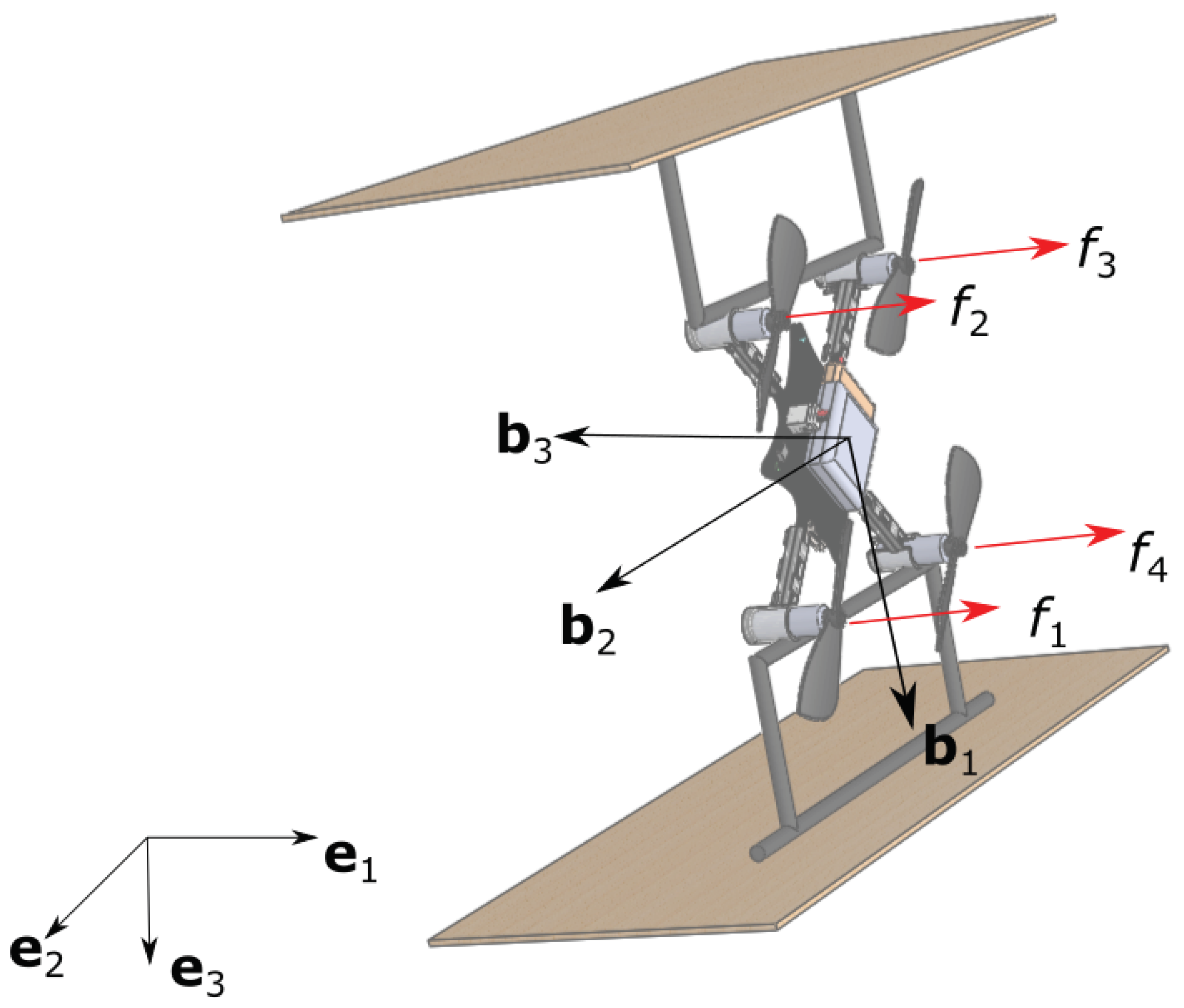
Consider an inertial reference frame
centered at
O with orthogonal basis vectors
,
,
and let
be a body-fixed reference frame centered of the aircraft center of mass,
G, with basis vectors
,
, and
as shown in
Figure 1. We represent the orientation of
with respect to
using the four element quaternion vector [
27]
such that the basis vectors of frame
and
are related by
where ⊗ represents quaternion multiplication [
27] and
is the quaternion conjugate. Since the vehicle will be required to pitch to near 90 degrees, a Euler angle attitude representation would be prone to near singularities [
28], motivating use of the quaternion approach. Throughout this paper, we assume all quaternion vectors are properly normalized and therefore
. For notational convenience, we define the rotation operator
which transforms the three dimensional vector
by the quaternion
as defined in Equation (
1). We also omit the superscripts on the quaternion to simplify the presentation.
The position of the center of mass is given in inertial frame coordinates as . The inertial velocity of the aircraft is represented in inertial frame coordinates as and in body frame coordinates such that . Similarly, let the angular velocity of frame with respect to be . Note the superscript indicates the frame in which the quantity is represented. To simplify the presentation, we omit the subscripts on and where appropriate.
The translational equations of motion of the center of mass are described by the vehicle kinematics and Newton’s 2nd law such that [
23]
where
M is the vehicle mass and
is the net force. Similarly, the equations of motion governing the attitude are [
23]
where
is the inertia tensor and
is the net moment about
G. The net force
and net torque
are the result of contributions from each rotor, gravity, and the aerodynamic properties of the attached air foils. The following section derives models of the forces and torques on the body.
2.2. Force Definitions
The dynamics of the winged quadrotor are governed by the four thrust vectors generated by the rotors
, the aerodynamic forces generated by the airfoils
, the gravitational force
, and induced drag forces
. The net force vector is the sum of all forces
The rotors generate a force vector along the
axis, as illustrated in
Figure 1, and net moments about each of the respective
axes. Ultimately, the vehicle is controlled by adjusting motor speeds such that the net force and moment vectors yield the desired vehicle acceleration. Each rotor generates a force according to
and a moment according to
where
and
are the respective thrust and moment coefficients for the rotors, and
is the angular velocity of the
ith rotor [
29]. The rotor force vector can be defined as
There is also an effective drag force which is caused by blade flapping and induced drag as the forces generated on the rotors changes as the quadrotor translates through space. These forces can be modeled using a linear drag model [
29],
where
is a diagonal matrix of damping coefficients corresponding to the effective drag constants along each of the
frame principle axes. The gravitational force expressed in the
frame is defined by
where
.
The airfoils generate lift and drag forces based on the speed of the flow over the airfoil, the angle of attack (
), the air density (
), planform area (
A) and the lift and drag coefficients for the airfoil geometry. The lift and drag forces of a single airfoil can be determined using the following equations [
26]
where the angle of attack is defined from the velocity components using
and the equations for the lift coefficient (
) and drag coefficient (
) are functions of the angle of attack, these coefficients are determined from [
26], and are further discussed in
Section 2.3.
Considering contributions from both wings, the total force generated by the airfoils is
where
is constant scale factor given that bi-plane configurations do not produce double the lift of a mono-plane design since both airfoils are operating in close proximity to one another [
30]. Here, we assume the drag caused by any side-slip is negligible. Further details on the aerodynamic model are presented in
Section 2.3.
One design decision that must be considered is the interaction between the rotors and the airfoils. In the present work, we propose a design where the airfoils are offset from the axial flow of the rotors. It is our assertion that this will minimize the effect of the rotors on the aerodynamics of airfoils and vice versa. While the thrust model in Equation (
5) and aerodynamic model described by Equation (
8) provide a baseline for the purpose of control design, a higher fidelity vehicle model would include an aerodynamic model that more accurately accounts for the interactions. Fully characterizing these interactions would require a comprehensive thrust lift analysis of the proposed vehicle design which is beyond the scope of the present work and subject to ongoing research.
The low-level control commands sent to the vehicle are a set of voltages for each of the motors. Here, we assume the motor speed transients can be neglected thus, the voltage will be directly proportional to speed. For the purposes of more fully representing the dynamic model of the system and for aiding in synthesizing the controller, it is helpful to define a mapping from rotor speeds to forces [
24]
where
l is the moment arm from the spinning axis of the rotor to the center of gravity G,
T is the thrust force generated by the rotors and
is the net moment vector in the
frame. This expression for
is used as the control input, and the inverse of this matrix is used to convert the commanded control input vector to rotor speeds.
By substituting the net force vector into Equation (
2) and the net moment vector from Equation (
11) into Equation (
3), the full non-linear equations of motion for the vehicle can be written
This model is used as the basis for analysis, controller design, and simulation in
Section 3 and
Section 4.
2.3. Aerodynamic Model
In the design of the proposed vehicle modification, certain considerations must be made. Due to the size and speed of the vehicle, the airfoils will operate at low Reynolds numbers (). To this end, we seek airfoils that will provide favorable performance characteristics in this range of Reynolds numbers while simple and lightweight to address the size constraints of the platform.
For the vehicle design, we select a flat plate airfoil, which greatly simplifies design and implementation. A flat plate airfoil can also be fabricated from balsa wood or thin foams and added to the vehicle with very little additional mass. This work considers balsa wood in the design without loss of generality.
In addition to simplicity of design, the flat plate airfoil has some other benefits compared to other symmetric standard airfoils such as a NACA 0012. It has been shown in the literature that for low Reynolds number applications flat plate airfoils have more favorable aerodynamic characteristics [
26,
31,
32]. In particular the NACA 0012 exhibits highly non-linear lift slopes at low Reynolds numbers [
26]. Additionally, Laitone [
31] concluded the NACA 0012 airfoil is highly sensitive to variations in Reynolds number which make it unsuitable for low Reynolds number applications, further recommending that flat plate airfoils should be used in these applications. This has an important implication for the present vehicle design since the vehicle must hover, transit slowly, and travel at higher speeds. Therefore, the range of Reynolds numbers experienced by the airfoil will vary significantly.
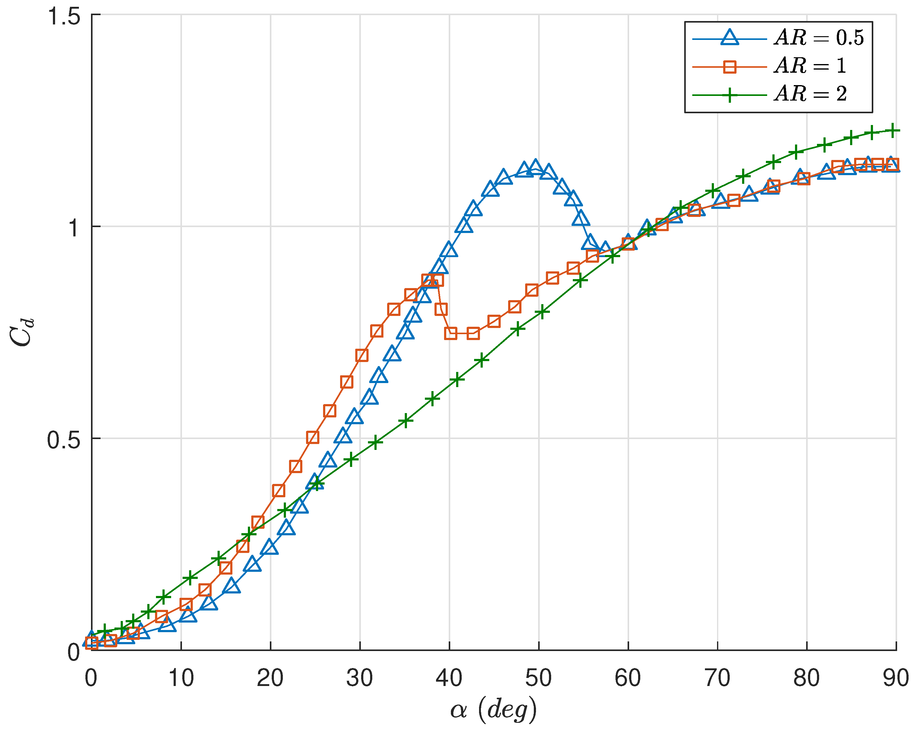
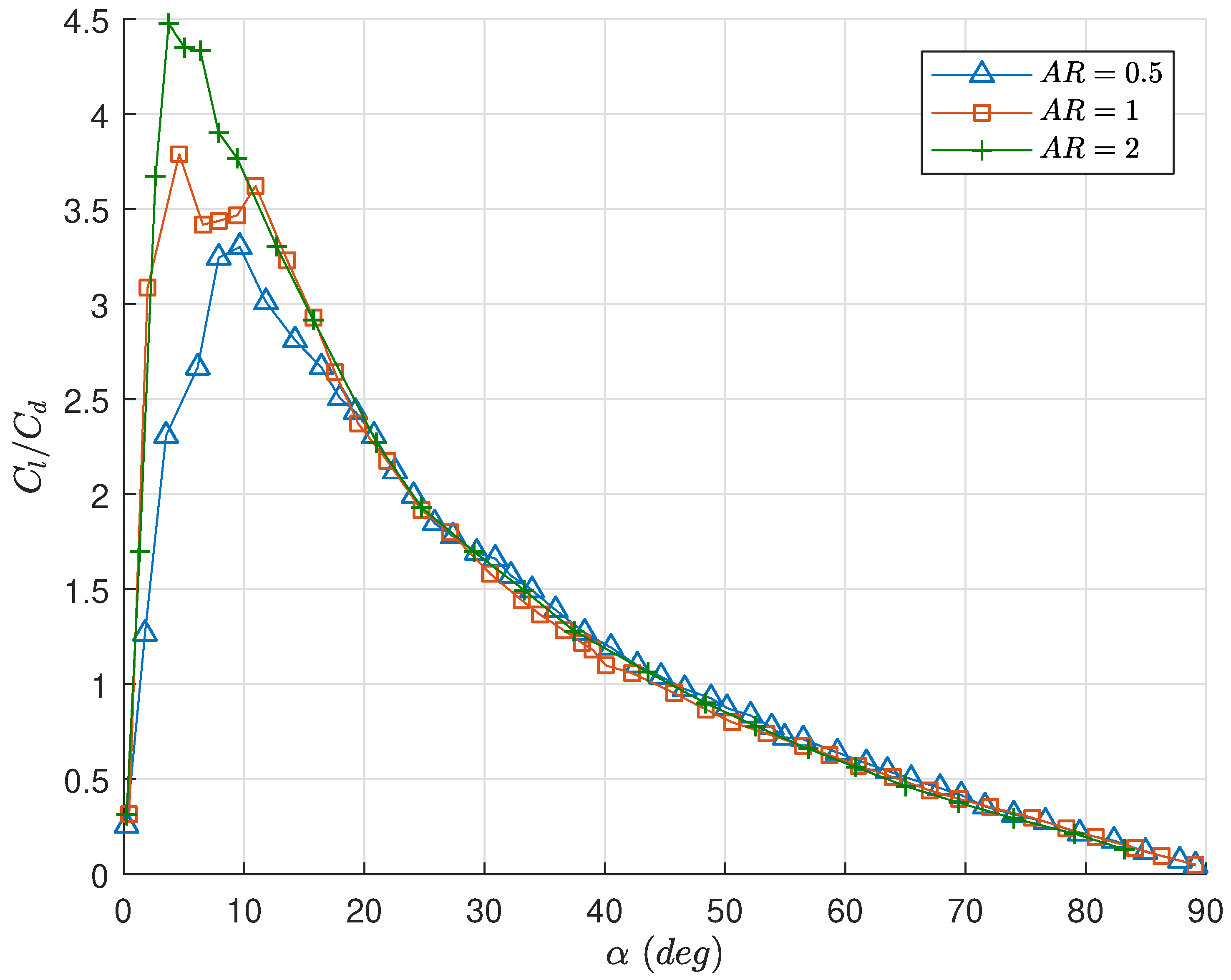
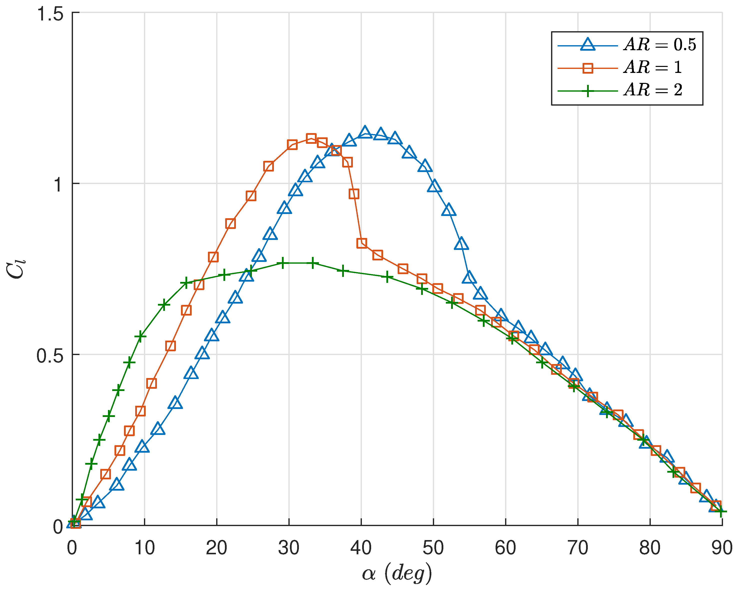
A transitioning vehicle will operate in a range of angle of attacks,
degrees, and prior works have suggested models that may adequately approximate the steady-state aerodynamic forces in the entire range. Okamoto and Azuma [
26] conducted a series of experiments on flat plate airfoils in the 0 to 90 degree angle of attack range, with various geometries and aspect ratios. The lift and drag coefficient curves for a rectangular flat plate from [
26] are utilized for
and
in Equation (
8). The lift and drag curves used are shown in
Figure 2 and
Figure 3, respectively, reproduced from [
26]. For further details regarding these curves, the reader is referred to [
26]. We consider three rectangular aspect ratios for the design of the vehicle
. These aspect ratios along with the overall dimensions of the airfoils are chosen to keep the size of the vehicle such that it will still be effective during near-hover behaviors. The geometries considered result in airfoils with the same planform area and mass across each aspect ratio. Additionally, here we do not consider sweep angle, although it could be an interesting topic of future study.
Figure 4 shows the lift to drag ratio for three airfoils considered. From these data it can be seen that the airfoil with
has the highest lift to drag ratio. In addition, the peak lift to drag ratio occurs at a lower angle of attack than
or
airfoils. For angle of attacks greater than 20 degrees, all three aspect ratios have similar lift to drag ratios. This indicates that, during a near-hover maneuverer where the angle of attack is high, there is no advantage of one aspect ratio over another given equal wing area.
The geometric parameters for the airfoils are displayed in
Table 1. Note the wing mass (
) represents the combined mass of both airfoils given the proposed design is a bi-plane.
3. Trim Analysis
The modeling results of
Section 2 facilitate a trim analysis to determine equilibrium conditions for steady-level forward flight. We consider the steady-level flight condition since the aerodynamic model utilized was developed under steady-state conditions. Ultimately, we seek a control strategy that is robust to aerodynamic model errors associated with transient dynamics. An equilibrium flight condition satisfies
Furthermore, in steady-level flight, we assume the roll angle (
), lateral velocity(
v), and climb rate (
) are zero. Without loss of generality, we assume steady-level flight along the inertial
axis such that the yaw angle is zero. Under the simplifying longitudinal dynamics assumptions, the quaternion is equivalent to a pitch angle (
). In inertial coordinates, the equations of motion for the longitudinal and vertical position become
where the total thrust force (
T) is defined in Equation (
11) and we assume
D and
L can be adequately modeled using Equation (
8).
is the
ith component of the body drag vector defined in Equation (
6).
Equation (
14) can be used to determine trim conditions for the vehicle. The inertial frame accelerations (
and
) are set to zero and the speed and pitch are iterated over a range of feasible values for a given thrust (
T). Iterating the analysis over thrusts in the interval
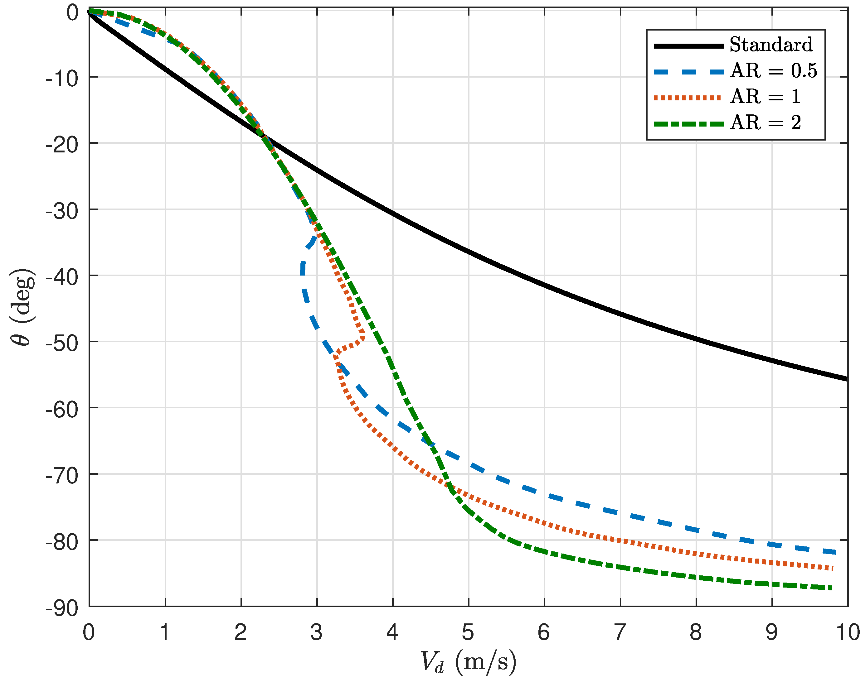
N yields the set of equilibrium speeds and pitch angles for steady level flight.
Figure 5 illustrates the relationship for wing aspect ratios of
, with comparison to a standard quadrotor (see
Appendix B). Note that
degrees corresponds to the airfoils being horizontal to the
-
plane and therefore generating no lift. As expected, larger
imply smaller angle of attack, less drag, and therefore a larger equilibrium speed is required to generate enough lift to support the aircraft weight. A smaller
corresponds to a larger angle of attack resulting in slower achievable translational speeds.
From this analysis, we can determine the nominal flight conditions for a given speed and climb trajectory. We also note that the airfoil selection has an effect on the nominal pitch angle for various speeds. There is a notch in the equilibrium curves for and . This indicates there are multiple trim conditions at those speeds. The standard quadrotor design must continue to increase its pitch angle to achieve higher speeds and thus must increase its thrust to maintain altitude; in contrast, the design with airfoils can pitch further and apply more thrust in the direction of travel and in theory achieve higher forward speeds.
4. Controller Design
In the control design of the modified quadrotor, we seek to develop a methodology that does not require two separate control strategies for low-speed near-hover maneuvers and high speed forward flight maneuvers. This section designs a low level flight controller assuming a higher level path planning algorithm addresses mission level trajectories. Commonly in the literature [
33,
34], path planning is achieved by assuming the vehicle follows the Dubins Car model kinematics,
where the inputs are the speed over ground (
), climb rate (
), and yaw-rate (
). Through this kinematic mapping, these commands can also be thought of as inertial frame velocity commands (
,
,
). Therefore, the trajectory could also be designed using inertial frame velocities if desired. Another note is that this presentation differs slightly from the approach commonly taken in the literature; the climb-rate is commanded directly rather than being a function of airspeed and climb angle. We take this approach since it is more intuitive for a quadrotor to directly accept a climb rate command, especially at low airspeeds.
With the assumption that mission level trajectories will be set by a path planner following the model in Equation (
15), we desire a control strategy that will track a given command (
,
,
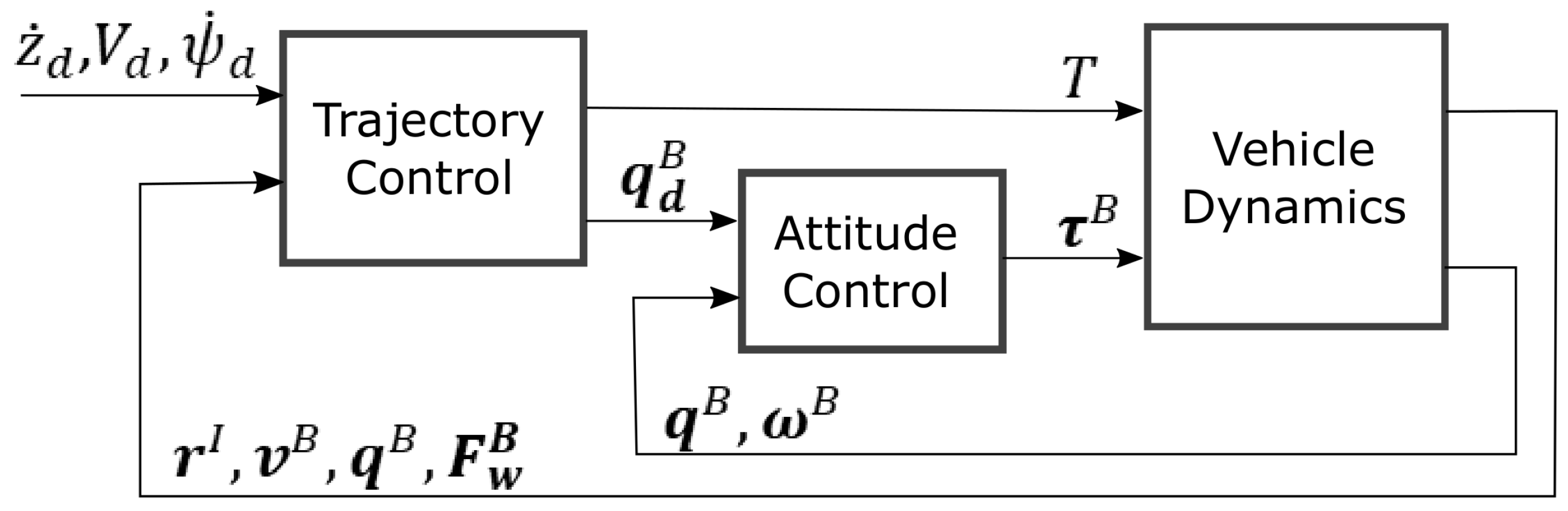
). To achieve this requirement, we use a cascaded control architecture with a higher level trajectory controller and a lower level attitude controller. A block diagram of the controller architecture is shown in
Figure 6, which shares similarity with previous works [
2,
21]; we now consider the application of this approach to a quadrotor with airfoils.
Section 4.1 describes the outer loop trajectory controller and
Section 4.2 presents the inner loop attitude control strategy. The overall premise of this approach is that the trajectory controller calculates the required net force vector to track the desired trajectory in space and time, then the attitude controller orients the vehicle to align the achieved net force vector with the required net force vector.
4.1. Trajectory Controller
The ultimate goal of the aircraft design is to track the trajectory while reducing the thrust used to navigate. Thus, it is desirable for the controller to take advantage of the lift generated by the airfoil in order to maintain altitude and to turn. In other words, while it is possible for the quadrotor to maintain altitude with just the thrust vector, it is preferable for it to maintain altitude using the airfoils.
For this work, we consider the vehicle tracking a speed over ground (
) on the
-
plane, a climb rate (
) and altitude (
) in the
direction and a yaw rate (
) about the
axis. The trajectory control strategy consists of two parts, the longitudinal control and lateral control. The first component of the longitudinal control is designed to track a speed along a path in the
-
plane, the second component tracks a desired altitude and climb rate. The control is given by
where the first element is a PI-controller regulating the speed of the vehicle in the
-
plane, whereas the third element is a PID-controller tracking an altitude (
z) and climb rate (
). The superscript
on the commanded force vector indicates this quantity is expressed in path coordinates of the trajectory. The thrust vector in the path coordinates is computed using
In this equation, the net force from the airfoil represented in the
frame is rotated along the pitch axis by
, this results in the lift and drag forces from the airfoil along the path. This can be considered an intermediate rotation. This quantity along with the gravity vector are subtracted from the commanded force. The result is the thrust force vector required by the quadrotor to achieve the commanded force. The thrust command (
T) sent to the vehicle can be computed from the magnitude of the thrust vector represented in the inertial path frame
The desired pitch angle can be set by determining the angle between the commanded inertial frame vector from Equation (
17) and the
direction.
For the lateral control of the vehicle, we seek to achieve a yaw rate which has the effect of curving the path of vehicle. To determine yaw rate we use a coordinated turn condition; to achieve a curved trajectory the lift vector is rotated towards the inside of the turn which results in a centripetal acceleration. The coordinated turn assumption gives the roll and yaw rate relationship as
Since this equation is used to determine the roll angle set point, the desired speed and yaw rate are used in the expression rather than the current speed and yaw rate. Lastly, the desired heading can be determined from integrating the desired yaw rate.
The desired attitude states (
) are then converted to a desired quaternion using Equation (
A1). The outputs of the trajectory controller are the total rotor thrust (
T) and the desired quaternion (
) Further details on the kinematic conversions can be found in
Appendix A.
4.2. Attitude Controller
The inner attitude control loop is used to track the desired orientation set by the trajectory tracking control. The quaternion formulation is used to avoid gimbal lock since the vehicle will be required to pitch to large angles (low angle of attack) to most effectively use the airfoils. The presentation here is derived from the work by Fresk and Nikolakopoulos [
35]. The error between the desired quaternion and the vehicle frame quaternion can be determined with
The control law is then
where the first expression in Equation (
23) represents the torque required to align the two quaternion frames in the inertial frame. The matrices
and
are diagonal gain matrices with positive gains. The
function, effectively takes the conjugate of the error quaternion in the event
is negative. This would be the case when the error is larger than 180 deg. This conjugation is used to ensure the controller takes the shortest path to the desired orientation. The inertial torque is rotated to the body frame and the body rates are used to complete the commanded torque. The results from Equations (
18) and (
23) are used with Equation (
11) to determine the desired rotor speeds for the quadrotor.
5. Results and Discussion
To test the control methodology, the kinematic and dynamic equations from
Section 2 along with the controller from
Section 4 were implemented in Matlab and Simulink. As a basis of comparison for the quadrotor modified with the airfoils (herein referred to as modified), a standard quadrotor model (herein referred to as standard) was implemented. A typical linear tracking controller was used to control the trajectory of the standard model; the details of which are presented in
Appendix B.
Table 2 shows the parameters for both models. Differences in mass of the standard and modified models is attributed to the mass of the airfoils. Calculation of the mass of the airfoils uses the density of balsa wood with the specified geometric volume. The inertia properties of both models were determined using a computer aided design model for each. The other geometric properties of the vehicle were determined from direct measurements of the vehicle. The thrust and moment coefficients were determined using a static thrust test and approximations based on the scale and performance of the vehicle. Note the emphasis of this study is to determine the effect of the airfoils on performance; the simulations were designed to be agnostic to many of the parameters. The two most important parameters are the mass and the induced drag coefficients. The body drag parameters were determined by considering a maximum reasonable speed for the a quadrotor of this size and available thrust. We assume the induced drag in the
direction is negligible for the modified quadrotor since it will be small with respect to the drag caused by the airfoils.
There are two goals of this study. First, we desire to validate controller performance over a feasible range of trajectories and scenarios. Secondly, we seek to determine how much net thrust savings can be obtained by adding airfoils to the vehicle. This can also help to determine the flight profile trade space for utilizing the airfoils versus using a standard quadrotor configuration.
5.1. Controller Performance
In testing the performance of the controller, there are several considerations to be made. The controller should provide satisfactory tracking performance across the full range of operating conditions. Several simplifying assumptions were made in the derivation of the model, so the controller must still perform adequately in the presence of uncertainties. To model uncertainties in the aerodynamic model and thrust models, we include first order Markov random walk driven by Gaussian noise added to both the net force and net moment vectors.
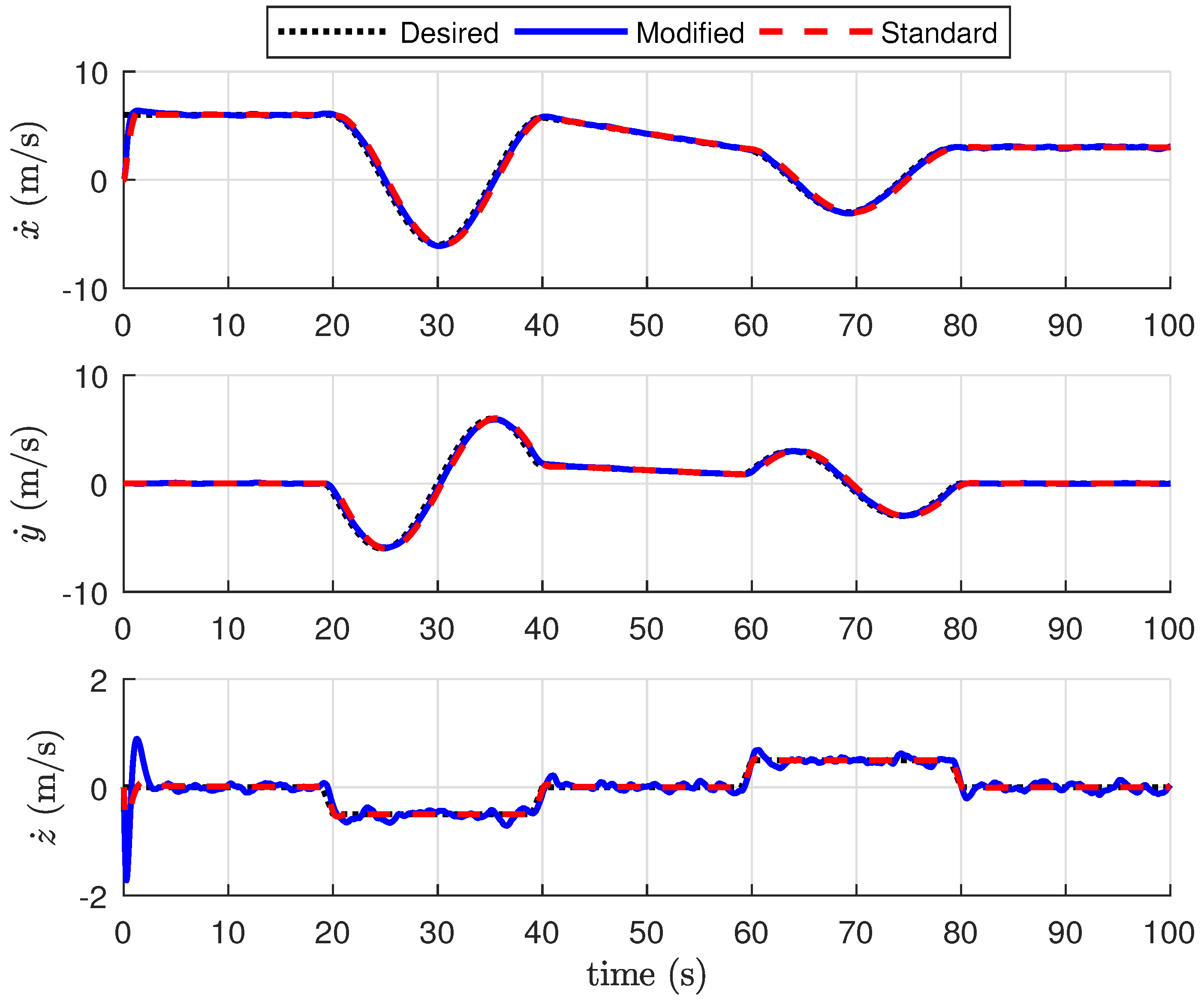
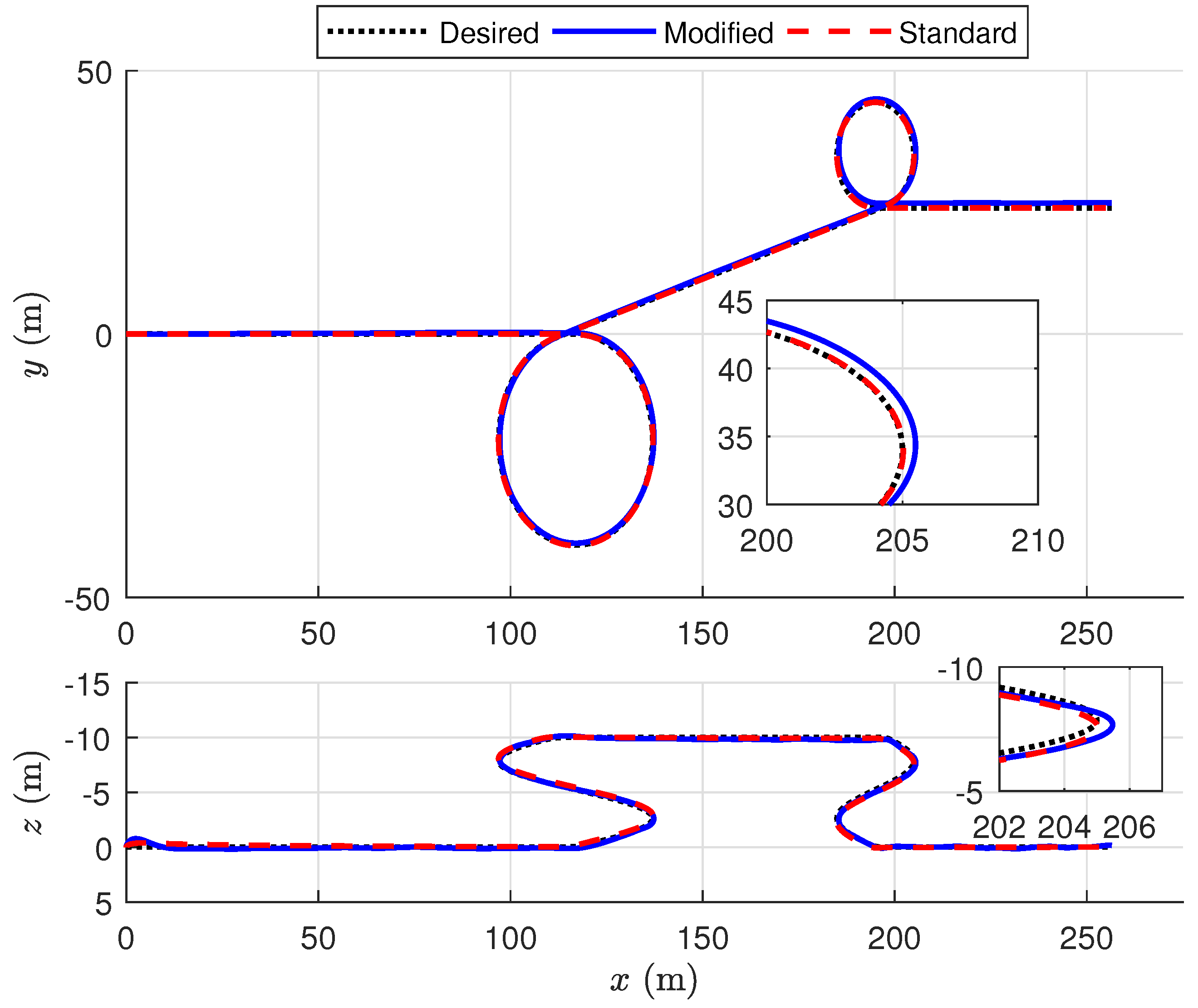
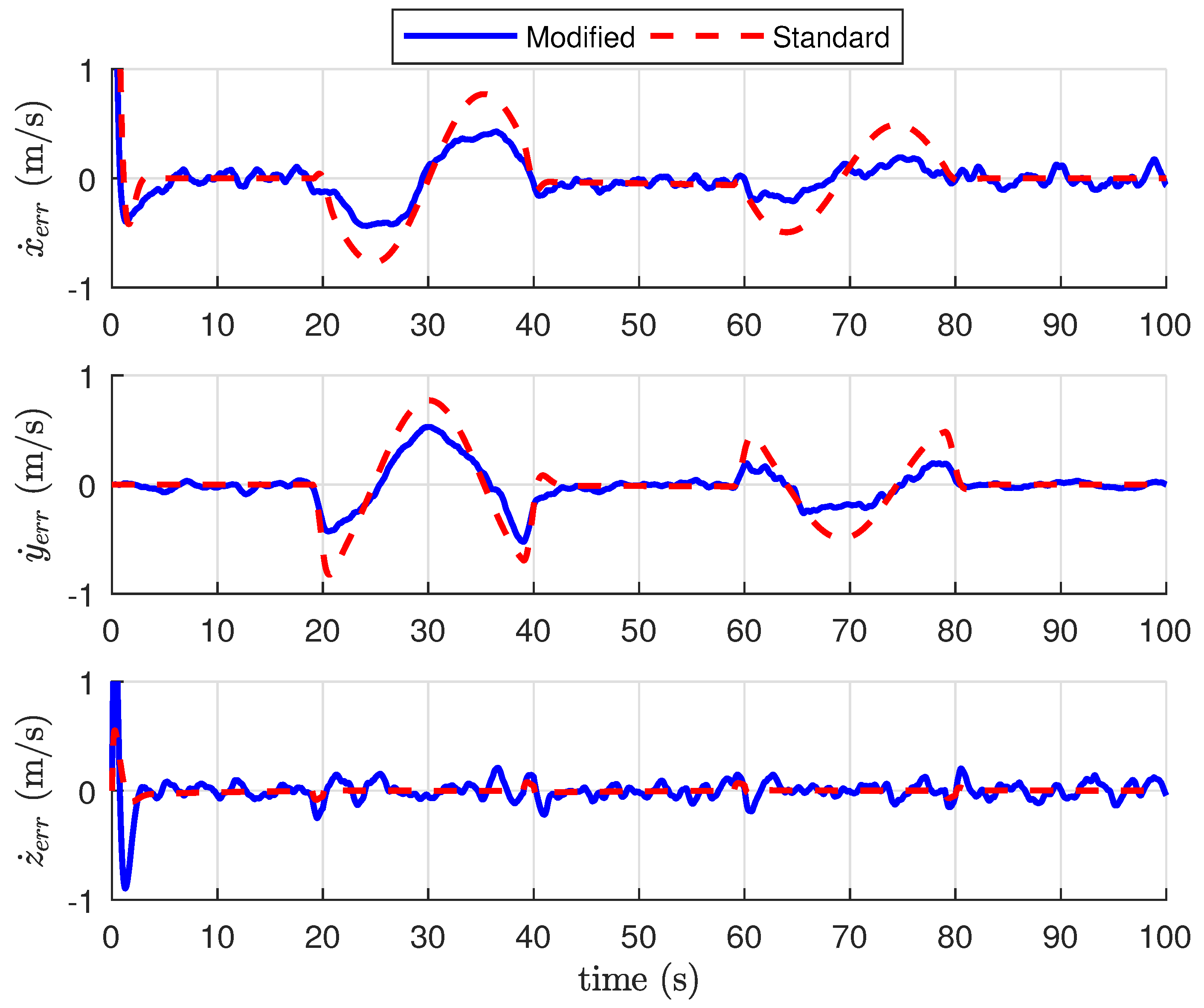
Figure 7 presents the tracking performance of the controller for the modified airframe with
. The results shown are representative of the other scenarios and aspect ratios considered. The maneuver begins with the vehicle starting from rest and accelerating to 6 m/s. Following the acceleration, the vehicle enters an ascending helix at a constant yaw rate of 0.3 rad/s (20 m radius). The vehicle gradually slows to 3 m/s before entering a descending helix at a constant yaw rate of
rad/s (10 m radius).
Figure 7 shows the tracking performance of the inertial frame position.
Figure 7 (top) illustrates the vehicle trajectory in the
x-
y plane, whereas
Figure 7 (bottom) shows the trajectory in the
x-
z plane. Note the modified quadrotor tracks the desired position trajectories although with less precision than the standard quadrotor model.
Figure 8 shows the tracking of the velocity trajectory in the inertial frame. The standard and modified quadrotors converge to the desired state after transients associated with the changes in the desired velocity. As expected, the tracking performance of the velocity is better than that of the position since the controller is designed to track an
x-
y plane velocity and an altitude and yaw rate. Velocity tracking error is shown in
Figure 9. Note the tracking error converges to zero after the transients. There is also an oscillatory error during each of the helix maneuvers that is caused by the phase lag in the tracking of the reference signal.
5.2. Efficiency Comparison
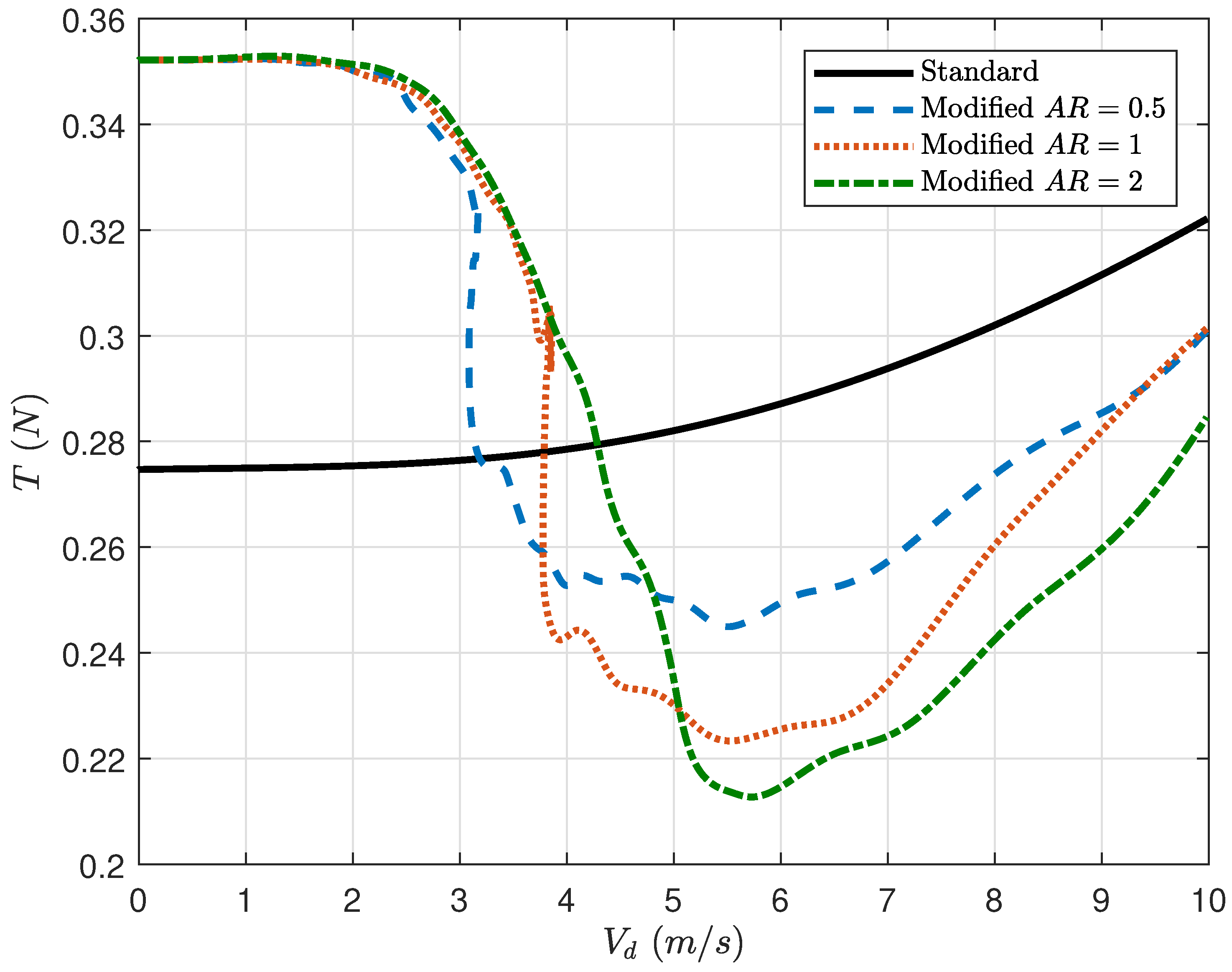
To simplify presentation of the results for the efficiency comparison, the next set of simulations were conducted without the effects of aerodynamic disturbances. As an initial study to understand the efficiency of the modified quadrotor, the vehicle was commanded at a constant forward acceleration with a constant altitude. The vehicle started at rest and accelerated to 10 m/s. This range was chosen as a reasonable range of speeds for a vehicle of the size and capability of the one modeled. This test determines the velocity at which the wings will provide the maximum benefit. Simulations were run across each of the three aspect ratios considered. From the dynamic analysis in
Section 3, we hypothesized that the maximum benefit will occur within 3–5 m/s for the parameters and aspect ratio considered.
Figure 10 compares the thrust force required by both quadrotor configurations over the course of the simulation. Note as the speed of the standard quadrotor (black solid line) increases, the thrust required to maintain that speed while holding altitude also increases due to increased drag forces. For the modified quadrotor, the thrust force has a sharp decrease just prior to 3 m/s for all aspect ratios. Each aspect ratio airfoil experiences its overall minimum thrust slightly above 5 m/s. As the vehicle continues to increase in speed, the thrust force begins increasing again as the model must overcome increasing drag forces. It is also worth noting that the
(blue dashed line) has the lowest thrust at 3–3.75 m/s, the
(red dotted line) has the lowest thrust at 3.75–5 m/s, and the
(green dot-dashed line) has the lowest thrust at >5 m/s. Interestingly, the
and
have almost the same force requirement at >9 m/s. Perhaps the most important takeaway from this figure is that the crossover point between the thrust force for the modified and standard quadrotors is approximately 3.2 m/s, 3.75 m/s, and 4.25 m/s, for the respective increasing aspect ratios. This implies that for missions slower than this crossover point the standard quadrotor is more efficient but for faster speeds the modified quadrotor is more efficient. From these results, we conclude that the optimum speed at which the modified quadrotor should travel is dependent on the aspect ratio of the wing.
We now consider the performance of the standard and modified quadrotors across five different scenarios. Scenarios were chosen to test the performance of the controller for the modified platform and to quantify the benefit of adding airfoils. Each simulation lasted 100 s and was chosen to test the performance under specific flight conditions or maneuverers.
Results from the remaining five test scenarios are summarized below for each aspect ratio. The controller tracking performance for those scenarios is similar to that of scenario in the previous section. Description of the other scenarios tested are as follows.
Scenario 1 was designed to test the performance in maneuverer that might exist in a typical mission. The first leg of the scenario was a constant climb rate to altitude with a 2 m/s forward speed for 20 s. At the 20 s mark, the quadrotor then accelerated to 4 m/s, and ultimately up to 6 m/s at the 40 s mark. At the 60 s mark, the quadrotor was commanded into a constant radius turn with a constant increase in altitude. Then, at the 80 s mark, the quadrotor was commanded to a decreasing altitude while maintaining the same desired radius turn.
In Scenario 2, the vehicle was commanded to a constant forward speed of 6 m/s then a constant 1.5 m/s climb rate causing an increasing altitude and then a negative climb rate causing a decrease in altitude changing every 20 s. This scenario was chosen to determine the effect of the airfoils when climbing or descending.
In Scenario 3, the vehicle was commanded to a forward speed of 6 m/s at a constant altitude. The vehicle was then commanded to track alternating positive and negative yaw rates. This scenario was chosen to evaluate the effect of the airfoils for tracking a turn.
In Scenario 4, the vehicle was commanded to a forward speed of 6 m/s and track a positive yaw rate and climb rate (ascending helix), and then a negative yaw rate and negative climb rate (descending helix). This scenario was chosen to evaluate the effect of the airfoils under turns with increases and decreases in altitude.
In Scenario 5, the vehicle was commanded to maintain a hover to determine the effect of the airfoils when they are providing no benefit.
As a metric for comparing the overall performance difference between the standard and modified quadrotors, we consider the energy consumed in generating thrust. The power output of the rotors can be determined by summing the moment generated by the rotors times their respective angular speeds. Since the moment generated by each rotor is
, we can write the total power consumption as
The energy consumed can then be determined by integrating the power over the duration of the simulation such that
Table 3 summarizes the total energy consumed for all for test scenarios. The modified quadrotor, for all aspect ratios, requires less total force compared to the standard airframe with the exception of Scenario 5 (pure hover). This was expected from the constant acceleration simulation, as we determined the benefit crossover point is above 3.0 m/s. Additionally, comparing Scenarios 3 and 4, there is little to no effect in the overall energy consumed when increasing and decreasing the altitude. This is reasonable as the energy lost during increasing the altitude is regained when the altitude drops again.
Considering the most common speed range for a vehicle of this size and maneuverability is 0–6 m/s, it is challenging to conclude which airfoil choice is best. More helpful in application would be to constrain transit behaviors to the speed which most effectively utilizes the airfoils. During near-hover, all the airfoils have the same detriment, therefore it is more important in executing trajectories to spend more time above the crossover point for the respective aspect ratios than below it to justify the use of the airfoils over a standard quadrotor. However, at the appropriate forward speed one can gain up to 35% energy savings versus losing 45% during hover, thus one can begin to design trajectories, with respect to mission requirements, which most effectively optimize the overall energy profile of the vehicle. The results presented here also motivate the design of airfoils which are very lightweight. Decreasing the mass of the airfoils will effectively shift the thrust versus speed curve downward by the incremental percentage of the airfoils mass over the standard quadrotor. Both topics are subjects of ongoing research.
6. Conclusions
This paper presents a dynamic model, trim analysis, and control design for a micro quadrotor outfitted with airfoils. The dynamic model of the modified quadrotor includes the aerodynamic forces for a rectangular flat plate. We design a feedback controller that effectively tracks velocity trajectories in the inertial x-y plane while simultaneously tracking an altitude and climb rate in the presence of aerodynamic and thrust disturbances.
Simulation results for three different aspect ratio airfoils show that addition of the airfoils results in a significant improvement in performance provided the vehicle is moving faster than 3.0 m/s. During near hover maneuvers, the airfoils result in a thrust detriment proportional to the added weight. During high speed maneuvers, the airfoils reduce the required thrust by up to 35%. To provide net benefit during the overall mission, periods of slow behaviors must be compensated for by high speed transits.


