Proceeding Paper

Design of a Cable-Driven Actuator for Pronation and Supination of the Forearm to Integrate an Active Arm Orthosis †

by
Eduardo A. F. Dias
* and
Rafhael M. de Andrade
Department of Mechanical Engineering, Technological Center, Universidade Federal do Espírito Santo, 29075-910 Espírito Santo, Brazil
*
Author to whom correspondence should be addressed.
Presented at the First International Electronic Conference on Actuator Technology: Materials, Devices and Applications, 23–27 November 2020; Available online: https://iecat2020.sciforum.net/.
Proceedings 2020, 64(1), 4; https://doi.org/10.3390/IeCAT2020-08511
Published: 21 November 2020

Abstract

:
The pronation/supination of the forearm are important movements to properly accomplish the activities of daily living. While several exoskeletons have been proposed for the rehabilitation of the arm, few of them have actively implemented the movements of pronation/supination. Often, the addition of this degree of freedom to the mechanism results in a bulky and heavy structure. Consequently, the overall exoskeleton is too big for a wearable solution. This paper proposes a digital prototype and kinematic evaluation of a cable-driven orthosis for pronation/supination movement assistance. The actuator is based on an open ring (semi-circle) to be attached to the forearm, while a stationary guide drives the ring into a rotary movement. By considering anthropomorphic data in the design stage, it is possible to develop a rigid, compact, and high power to weight ratio solution for the actuator responsible for pronation and supination. The proposed actuator can achieve the full range of motion for the activities of daily living and 83% of the rotation of the forearm total range of motion with a total mass of only 150 g.

1. Introduction

Neurological disorders, such as stroke and spinal cord injuries, are among the leading causes of disabilities all over the world, resulting in muscular weakness and neuro-muscular damage. These conditions lead to an enormous impact in the quality of life, reducing the patient’s capacity to accomplish basic activities of daily living (ADLs) and causing a life-long dependency [1]. In this context, the use of robotic mechanisms (orthoses and exoskeletons) is becoming largely accepted as a novel therapeutic method for rehabilitation, due to relevant evidence of its effectiveness and the reduction in therapist active assistance that it allows [2,3,4,5,6]. Several robotic devices have been developed to assist the movement of the impaired upper limb and cooperate in rehabilitation [7,8,9,10].
It is known that repetition is a key factor in post stroke rehabilitation due to its influence in neuroplasticity [1,3,11]. Robotic devices have a potential role in facilitating highly repetitive training movements, especially when it comes to portable wearable exoskeletons, which allow the patient to progress with the training outside of the clinic. For patients to have the possibility of addressing the robotic rehabilitation outside of the clinics and at home, these devices must become more user friendly, and this can be achieved by creating lighter and slimmer mechanisms.
While some upper limb devices with these characteristics have been successfully developed, such as the MyoPro® (Myomo Inc., Cambridge, MA, USA), active orthoses still lack in degrees of freedom when compared to the full capabilities of the human arm. Few robotic rehabilitation devices have actively implemented the movements of pronation and supination [7,8,9,10,12] and even fewer have the purpose of being portable. Often, the addition of this degree of freedom to the mechanism results in a bulky and heavy structure. Consequently, the overall exoskeleton is too big for a wearable and portable device. An alternative solution to this problem has been proposed [12] but it results in a non-backdrivable and complex mechanism which may also lead to difficulties in manufacturing.
To address these shortcomings of forearm orthosis, in this work we propose a new design and a kinematic analysis of a cable-driven actuator to allow for the pronation and supination movements of the forearm. While most of the exoskeleton with the commonly used C-shaped mechanism configuration have resulted in heavy and bulky structures, we propose that by considering anthropometric data it is possible to develop a proper design that leads to a lighter and slimmer mechanism. The designed actuator allows for 83% of the full range of motion of the forearm while weighing just 145 g.

2. Description and Characteristics of the Actuator

2.1. Biomechanics of the Forearm

To understand the design methodology applied in the development of the actuator, it is important to first comprehend the biomechanics of the forearm. During the pronation and supination, the radius rotates over the head of the ulna, allowing for the internal and external rotation of the forearm; these movements are extremely important when performing the activities of daily living. A study developed by [13] and later revisited by [14] evaluated that most of the activities of daily living (ADLs) can be performed with a range of motion between −50° and 50° measured from the neutral position. In addition, studies from [15,16] show that the angular velocities reach maximum values at 400°/s (7 rad/s) within eating and drinking tasks. These ranges for the ADLs are extremely important, while for the lower limb the range of motion and velocity analysis usually focus on the gait, for the upper limb a huge variety of different movements must be analyzed. Therefore, any device intended to replicate such movements should consider a mean value for the joint kinematics in a set of activities of daily living.
Another important aspect is that a considerable amount of relative angular displacement between the bones is observed in the distal portion of the forearm during rotation. This does not happen for the proximal side, due to the radius crossing the ulna in pronation. Such observation is important when considering the location of the exoskeleton contacts with the human body. This characteristic of the forearm during pronation and supinations allows for a brace to be positioned in the proximal extremity without considerable impairments to the rotations while bringing more stability and rigidity to the exoskeleton, also allowing for a better force distribution in the arm due to a greater contact area. This can be done while the actuation occurs only in the distal part of the forearm, in the wrist.

2.2. Design Concept and Methodology

Due to the complex biomechanics of pronation and supination of the forearm, reproducing such movements externally is also a complex task. The most basic approach for an exoskeleton to perform the forearm rotation consists of having a circular bearing over the forearm. Attaching the forearm to either the internal or external ring of the bearing produces a similar motion as for pronation and supination of the forearm when relative movement between the rings is produced. This approach has a huge downside of reducing the wearability of the exoskeleton, firstly because the user must put his arm through the bearing and secondly due to the large diameter bearings making the overall structure bulky. Depending on the diameter of the selected bearing, it could even reduce the achievable range of motion for elbow flexion as the outer ring may contact the biceps before full flexion is achieved.
Since the rotation of the forearm is limited to a maximum range of 180 degrees, it is logical to use a second approach by considering a section of a bearing, a C-shaped mechanism, exemplified in Figure 1. This actuator can have two basic configurations; the most common one consists of a fixed semi-circular rail and a moving cart that slides on the inside of the rail, and bearings can be used to reduce the sliding friction. The moving cart is attached to the user’s wrist using Velcro© straps or a thermoplastic brace. By applying a force to the moving cart, it moves along the rail, thereby pronating or supinating the forearm. Alternatively, the rail can be attached to the user’s wrist and the cart fixed to the orthosis structure; in this case, the rail moves with the cart in its outer side.
Although the C-shaped structure still commonly results in a heavy and large mechanism, some aspects of the overall construction can be reviewed to develop a more optimized actuator. Considering that, in most rehabilitation devices, rotation of the forearm is one of the furthest degrees of freedom, reduction in inertia at this stage will consequently decrease the needed torques in previous degrees of freedom. Bowden cable-driven actuators are a great alternative to reduce the overall inertia of the system, driving the actuator while the motor is located away from the user’s limb and maintaining a simple mechanical arrangement.
In a bowden cable actuator a pair of cables is guided inside flexible sleeves and the force is transmitted to the joint as displacement between the cable and the outer sheath is promoted. As the motor rotates, one of the cables is pulled while the other is released; this generates an antagonist motion of the cables relative to the sleeves. In Figure 1, the schematic of the cable management is exemplified, as the motor that rotates the red cable clockwise, attached to a pulley on the motor side, is pulled, it rotates the actuator counter-clockwise; the opposite is appropriate to the blue cable. It is also important that the cables are preloaded, to guarantee the absence of slack inside the sheath and prevent the cables from detaching from the pulley during motion.

2.3. Anthropometric Data Evaluation

A current drawback in the available rehabilitation devices is that they fail to provide a universal design capable of adapting to different subjects. This is comprehensible due to the extremely complex and amorphous geometries of biological surfaces, while a snug fit is required to deliver the forces efficiently and appropriately to the impaired limb. A consequence is that devices require custom parts sized specifically to the user’s limb. These parts are not a major inconvenience when considering simple ones such as braces and harnesses, but parts that are directly related to the actuation process, if custom made, may raise the production costs to a level in which the device becomes inaccessible to customers. A solution to this problematic is to design the parts based on anthropometric data that represent a sample of the population.
For the analysis of the measurements of the human forearm, the Hand Anthropometry of US Army Personnel [17] was considered. Important measurements are related to the distal extremity of the forearm: wrist circumference and wrist breadth. Since the mean values presented for both measurements in males are larger than for females, these were considered as a way of fitting a greater group. An important geometric characteristic of the forearm is its cross section geometry. The shape of human wrist was approximated to an ellipsis; therefore, for the estimations of dimensions for the actuator, the circumference and breadth of the forearm were used for 3D modelling. During the design process, a maximum wrist breadth of the mean value plus the standard deviation was considered for the maximum diameter of the wrist.
When defining the inner diameter, it is also important to evaluate the thickness of the thermoplastic used for the wrist fixation; this could make the inner diameter of the rail up to 10 mm thicker.

2.4. Mathematical Modelling

Bowden cable actuators can be kinematically analyzed as a set of pulleys with different diameters. This way, the reduction ratio between the pulley and the actuator is simply the ratio between their diameters. The schematics for the actuator presented in Figure 1 show that the actuator is composed of a motor attached to a pulley in which both cables are coupled. The other ends of the cables are attached to the actuator. When the cable is pulled by the motor it transmits the force to the actuator, moving it. As the displacement of the cables produces the motion of the actuator, we are able to relate the displaced cable length with the angular movement of the actuator. The same is valid for the relationship between the angular motion of the motor and the motion of the cable. This way, the angular displacement of the actuator can be defined as a simple function of the angular displacement of the motor as presented in Equation (1), where θA, DA and θP, DP are the angular displacements and diameters of the actuator and the pulley, respectively.
θ A = D P D A θ P
As DC motors alone reach high speeds but low torques, most commonly, instead of having the motor directly attached to the pulley, there will be a reduction stage before the driving pulley. In this case, the angular displacement of the pulley differs from that of the motor by a reduction factor. The important aspect of this characteristic is the fact that the overall reduction ratio (ir) intended for the actuator can be distributed in two reduction stages, one between the motor and the drive pulley and another between the drive pulley and the actuator. Once DC motors are easily instrumented with encoders, the relationship between the motor movement and the position of the actuator is of great importance as it allows for the position control of the actuator without the need for a potentiometer directly at the joint. This is possible only if a zero-backlash gearbox is used with the motor since the cable driven actuator, if properly tensioned, should not present slacks. Applying the reduction ratio ( i r ), to Equation (1), the relationship between the angular displacement of the motor ( θ M ) can be obtained (Equation (2)).
θ A = D P D A i r θ M
Although velocity and acceleration can be directly obtained from the differentiation of Equation (2), the torque applied to the actuator cannot be as easily obtained. The use of the bowden cable introduces additional drawbacks, the friction between the sheath and the steel cable being the most relevant one. The power transmission efficiency ( η r ) of the gearbox coupled to the motor should also be considered. The force transmission efficiency can be modeled similarly as for a cable sliding on a stationary pulley by Equation (3) [18,19], where μ is the Coulomb friction coefficient between the cable and the sheath and φ is the bending angle of the sheath.
F o u t F i n = e μ φ
By considering both the bowden cable transmission efficiency and the power transmission efficiency of the gearbox, the output torque of the actuator is calculated by Equation (4).
T A = D A D P i r η r e μ φ T M
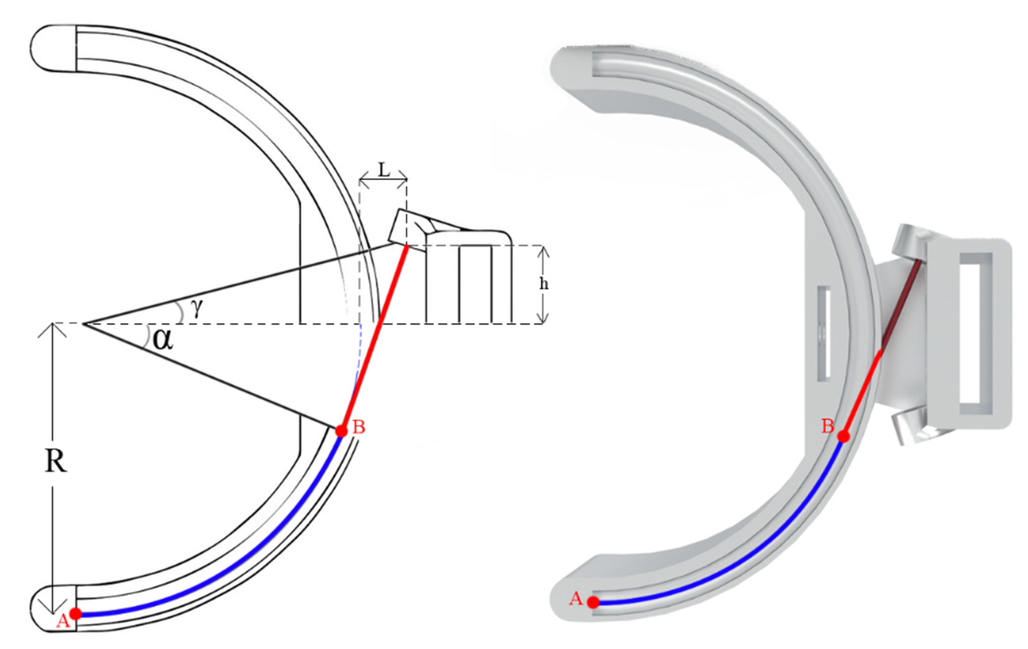
Since the cables are pre-tensioned, they will maintain a minimum length between the drive pulley and the actuator. Therefore, when leaving the sheath, the cable must be tangent to both the actuator and the pulley to avoid bending that would reduce the force transmission and cause friction and wear. At the actuator, the location for the output of the Bowden sleeve will be determinant to reach the maximum range of motion and power transmission. The red segment in Figure 2 shows the portion of the cable tangential to the actuator and the tangency angle α. When pulling the red cable, the point A moves towards the point B (tangency point) while α remains constant. As the point A passes B, the cable is no longer tangential to the actuator and α reduces; from that point, the force is not entirely transmitted from the cable to the actuator, and therefore, the output torque will decrease as A passes B. In order to achieve the greatest efficiency possible and constant force transmission, the movement of the actuator should be restricted to α; therefore, the maximum range of motion of the actuator is 180 o 2 α . Thus, by minimizing the tangency angle, the achievable range of motion of the actuator is maximized.
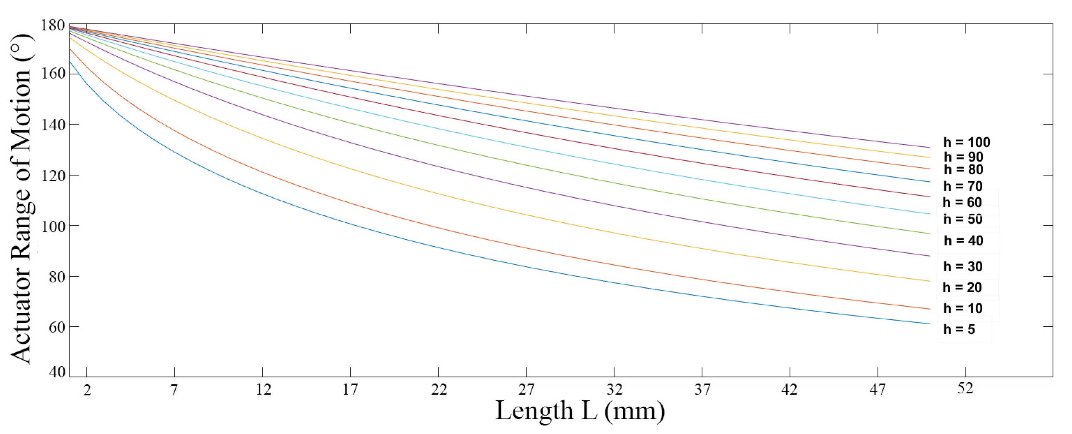
It is also important to notice that the distances L and h, presented in Figure 2, are related to the tangency angle. To keep the overall actuator as slim as possible, both dimensions must be minimized as well. These dimensions are defined by the construction of the cart and can be related to the angle γ, which is also a limitation to the range of motion of the actuator; consequently, the best condition for the construction of the actuator is for γ = α . The graph presented in Figure 3 shows the relation between the angle α and multiple values for h and L, showing that h is directly proportional to the range of motion while L is inversely proportional. It is observed that for small values of h, the range of motion rapidly decreases with the increase in L.

3. Results and Discussion

The choice of the maximum wrist breadth is the most important parameter and will allow for the evaluation of all other constructional aspects of the actuator. For this actuator, it was considered one standard deviation over the mean value ( 65.8 ±   4.5 mm); according to the statistics presented by [17], this should be enough to reach the 85th percentile of the population. Considering the thermoplastics used for this actuator, the diameters were defined for the OrfitEco (NS) with a thickness of 3.2 mm resulting in an inner diameter of 78 mm. The outer radius of the rail was defined as 46 mm, and 4 mm stainless steel balls as bearings were used for the movement of the rail.
To select the appropriate combination of h and L, a choice must be made to either maximize the range of motion or to minimize the size of the structure. Since both are extremely important characteristics, as the device must be capable of attending a good range of motion to perform the activities and must be slim to allow for better wearability, both variables must be carefully selected. In this case, a range of motion of 150° was chosen; as discussed previously, 100° would be enough to perform most of the activities of daily living, and the 25° extra margin for pronation and supination guarantees that a broad margin of movements can be performed. For that range of motion, the dimensions of L and h were defined as 9 mm and 12 mm, respectively, as the minimum values to achieve appropriate tolerances, considering an actuation radius (R) of 43 mm
To achieve low friction, a 4 mm PTFE bowden tube was selected with a 1.2 mm stainless steel cable resulting in a pair with low friction coefficient (μ). The bowden tube is attached to the actuator using PC4-M6 pneumatic couplings; these should not allow for the bowden tube movement while supporting the compression to the actuator structure resulting from the cable pulling. The dimensional optimization presented in the mathematical modelling is extremely important to minimize the overall weight of the C-shaped mechanism. The resulting structure presented in Figure 4a,b is manufactured in aluminum alloy 7075 T6 and weighs just 94 g. Considering all the necessary parts for the actuator, presented in Figure 4, which includes the structure, pneumatic couplings, bolts, bearing balls and the thermoplastic, the overall estimated weight is only 145 g.

4. Conclusions

The main goal of this study was to develop an actuator to perform the movement of pronation and supination on portable active orthoses for the rehabilitation of the upper limb. This actuator had the objective of being light and slim to provide better usability while still being adaptable to a vast population. The proposed anthropometric data evaluation is the basis for the construction and development of such an actuator. An analysis of the constructional aspects of the C-shaped mechanism was presented to allow for maximization of range of motion while also allowing for topological optimization.
The actuator that resulted from the design process presented can achieve 150 degrees of range of motion, while fitting the 85th percentile of the studied population. The most important characteristics to be analyzed in the resultant device are its low mass of only 145 g and the low-profile structure; combined, these should guarantee great usability. Further studies must analyze the structural performance of the actuator developed while loaded with the expected forces and torques from the activities of daily living.
A detailed description was given of the design process for a portable wearable actuator for pronation and supination for upper limb rehabilitation devices. The device allows for anatomical adaptability while still being slim and light and guaranteeing good range of motion for the rotation of the forearm when compared to the expected range for performing activities of daily living.
In future works, we intend to structurally analyze the actuator and the torque transmission throughout the movement. We aim to build a prototype to study aspects of the robotic rehabilitation for pronation and supination of the forearm and to evaluate the wearability of the device.

Conflicts of Interest

The authors declare no conflict of interest.

References

  1. Stinear, C. Prediction of recovery of motor function after stroke. Lancet Neurol. 2010, 9, 1228–1232. [Google Scholar] [CrossRef]
  2. Andrade, R.M.; Sapienza, S.; Bonato, P. Development of a “transparent operation mode” for a lower-limb exoskeleton designed for children with cerebral palsy. In Proceedings of the 2019 IEEE 16th International Conference on Rehabilitation Robotics (ICORR), Toronto, ON, Canada, 24–28 June 2019; pp. 512–517. [Google Scholar]
  3. Kwakkel, G.; Kollen, B.J.; Krebs, H.I. Effects of Robot-Assisted Therapy on Upper Limb Recovery after Stroke: A Systematic Review. Neurorehabilit. Neural Repair 2008, 22, 111–121. [Google Scholar] [CrossRef] [PubMed]
  4. Mehrholz, J.; Thomas, S.; Werner, C.; Kugler, J.; Pohl, M.; Elsner, B. Electromechanical-assisted training for walking after stroke. Cochrane Database Syst. Rev. 2017, 5, CD006185. [Google Scholar] [CrossRef] [PubMed]
  5. Singh, H.; Unger, J.; Zariffa, J.; Pakosh, M.; Jaglal, S.; Craven, B.C.; Musselman, K.E. Robot-assisted upper extremity rehabilitation for cervical spinal cord injuries: A systematic scoping review. Disabil. Rehabil. Assist. Technol. 2018, 13, 704–715. [Google Scholar] [CrossRef] [PubMed]
  6. Klamroth-Marganska, V.; Blanco, J.; Campen, K.; Curt, A.; Dietz, V.; Ettlin, T.; Felder, M.; Fellinghauer, B.; Guidali, M.; Kollmar, A.; et al. Three-dimensional, task-specific robot therapy of the arm after stroke: A multicentre, parallel-group randomised trial. Lancet Neurol. 2014, 13, 159–166. [Google Scholar] [CrossRef]
  7. Wu, K.-Y.; Su, Y.-Y.; Yu, Y.-L.; Lin, C.-H.; Lan, C.-C. A 5-Degrees-of-Freedom Lightweight Elbow-Wrist Exoskeleton for Forearm Fine-Motion Rehabilitation. IEEE/ASME Trans. Mechatron. 2019, 24, 2684–2695. [Google Scholar] [CrossRef]
  8. Perry, J.C.; Rosen, J. Design of a 7 Degree-of-Freedom Upper-Limb Powered Exoskeleton. In Proceedings of the First IEEE/RAS-EMBS International Conference on Biomedical Robotics and Biomechatronics, 2006. BioRob 2006, Pisa, Italy, 20–22 February 2006; pp. 805–810. [Google Scholar]
  9. Pehlivan, A.U.; Celik, O.; O’Malley, M.K. Mechanical design of a distal arm exoskeleton for stroke and spinal cord injury rehabilitation. In Proceedings of the 2011 IEEE International Conference on Rehabilitation Robotics, Zurich, Switzerland, 29 June–1 July 2011; Volume 2011, p. 5975428. [Google Scholar]
  10. Rocon, E.; Ruiz, A.F.; Pons, J.L.; Belda-Lois, J.M.; Sanchez-Lacuesta, J.J. Rehabilitation Robotics: A Wearable Exo-Skeleton for Tremor Assessment and Suppression. In Proceedings of the 2005 IEEE International Conference on Robotics and Automation, Barcelona, Spain, 18–22 April 2005; pp. 2271–2276. [Google Scholar]
  11. Kleim Jeffrey, A.; Jones Theresa, A. Principles of Experience-Dependent Neural Plasticity: Implications for Rehabilitation after Brain Damage. J. Speech Lang. Hear. Res. 2008, 51, S225–S239. [Google Scholar] [CrossRef]
  12. Dežman, M.; Asfour, T.; Ude, A.; Gams, A. Exoskeleton Arm Pronation/Supination Assistance Mechanism with A Guided Double Rod System. In Proceedings of the 2019 IEEE-RAS 19th International Conference on Humanoid Robots (Humanoids), Toronto, ON, Canada, 15–17 October 2019; pp. 559–564. [Google Scholar]
  13. Morrey, B.F.; Askew, L.J.; Chao, E.Y. A biomechanical study of normal functional elbow motion. J. Bone Jt. Surg. Am. 1981, 63, 872–877. [Google Scholar] [CrossRef]
  14. Sardelli, M.; Tashjian, R.Z.; MacWilliams, B.A. Functional elbow range of motion for contemporary tasks. J. Bone Jt. Surg. Am. 2011, 93, 471–477. [Google Scholar] [CrossRef] [PubMed]
  15. Buckley, M.A.; Yardley, A.; Johnson, G.R.; Carus, D.A. Dynamics of the upper limb during performance of the tasks of everyday living—A review of the current knowledge base. Proc. Inst. Mech. Eng. Part H J. Eng. Med. 1996, 210, 241–247. [Google Scholar] [CrossRef] [PubMed]
  16. Rahman, H.A.; Fai, Y.C.; Ming, E.S.L. Analysis of Human Hand Kinematics: Forearm Pronation and Supination. J. Med. Imaging Health Inform. 2014, 4, 245–249. [Google Scholar] [CrossRef]
  17. Greiner, T.M. Hand Anthropometry of US Army Personnel; No. TR-92/011; Army Natick Research Development and Engineering Center: Natick, MA, USA, 1991. [Google Scholar]
  18. Zhang, Q.; Sun, D.; Qian, W.; Xiao, X.; Guo, Z. Modeling and Control of a Cable-Driven Rotary Series Elastic Actuator for an Upper Limb Rehabilitation Robot. Front. Neurorobot. 2020, 14. [Google Scholar] [CrossRef] [PubMed]
  19. Schiele, A.; Letier, P.; Der Linde, R.V.; Der Helm, F.V. Bowden Cable Actuator for Force-Feedback Exoskeletons. In Proceedings of the 2006 IEEE/RSJ International Conference on Intelligent Robots and Systems, Beijing, China, 9–15 October 2006; pp. 3599–3604. [Google Scholar]
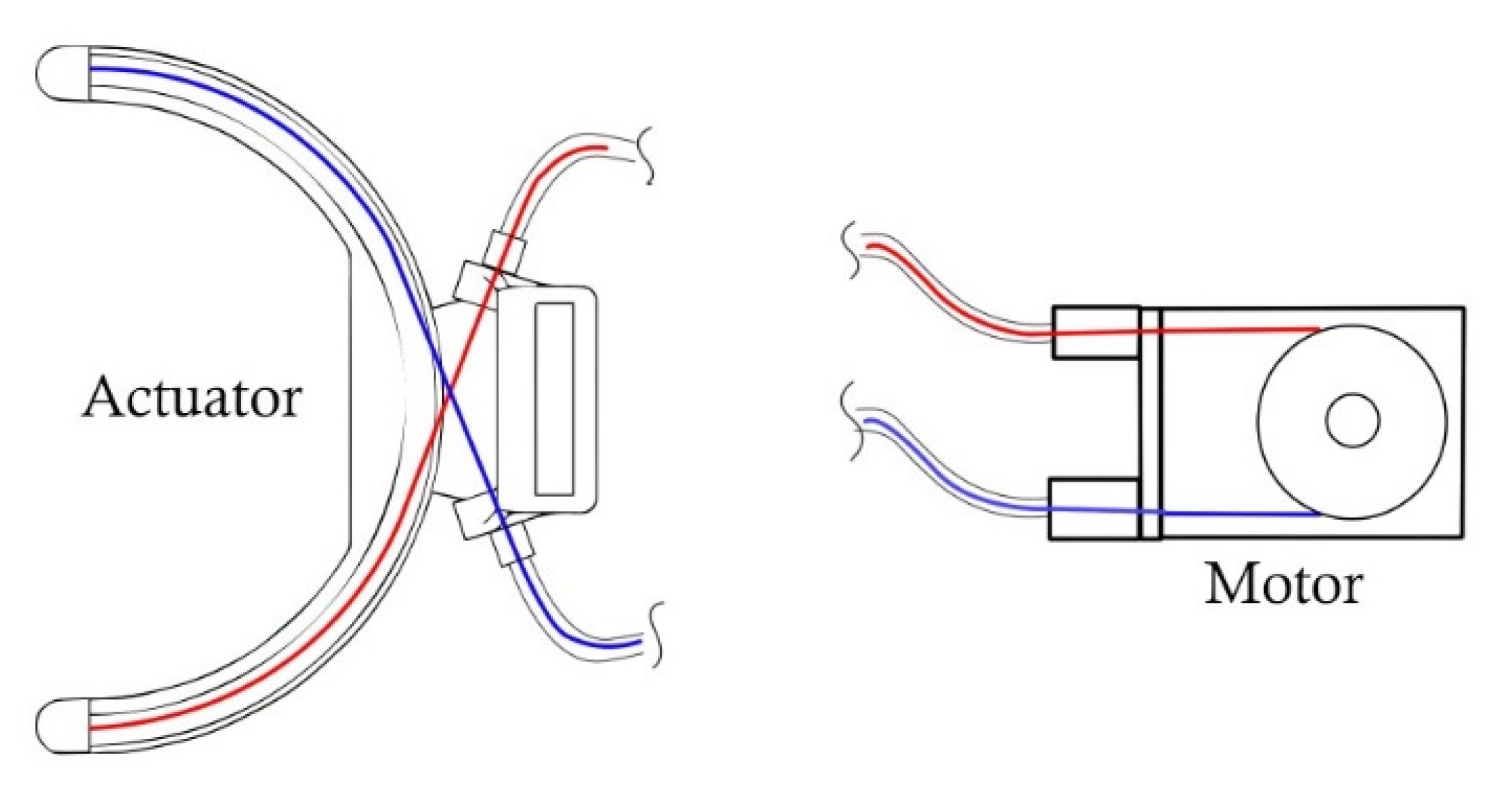
Figure 1. Schematic view of the of the Bowden cable actuator for pronation and supination of the forearm. Both the red and blue cables are attached to the motor, creating an antagonist movement.
Proceedings 64 00004 g001
Figure 2. Geometric characteristics of a C shaped actuator with moving rail.
Proceedings 64 00004 g002
Figure 3. Relationship between L and the range of motion of the actuator for different values of h, considering an actuation radius of 43 mm.
Proceedings 64 00004 g003
Figure 4. View of the resulting actuator mounted to the arm (c) and only the actuator structure with the pneumatic fittings (a) and (b).
Proceedings 64 00004 g004
Publisher’s Note: MDPI stays neutral with regard to jurisdictional claims in published maps and institutional affiliations.