1. Introduction
Pressure ulcers can be identified as a skin deformity in localised areas of the human body which are more prominent in the bony areas. Factors such as pressure, shear, friction or a combination of these could be the reasons for the formation of pressure ulcers. When the areas of the body get pressurised, the movement of blood vessels and vital nutrients to the muscles around the pressurised area gets minimised. When this happens, the capillary permeability increases resulting in the bodily fluids getting accumulated in the cavities of the tissue. This accumulation causes the tissue to die or to get damaged [
1]. The damage starts as a mere skin discolouration on the top most layer of the skin and may lead up to the bone through the tendon if not treated properly [
2]. In the worst case scenario, the patients might suffer amputations, and out of the pressure ulcer patients, the probability of amputation is as high as 42% [
3]. In the USA, in 2019, 60,000 people have been reported dead due to the complications such as sepsis and osteomyelitis caused by pressure ulcers [
4]. It is not only the deaths and the amputations that make pressure ulcers a significant impact, the cost of treatment of pressure ulcers show a significant impact on the economies as well. In the USA, the annual cost for the treatment of pressure ulcers is around 18.5 billion USD [
4]. In the UK, around £1.4–£2.1 billion is spent annually for the treatment of ulcers which is around 4 percent of the total National Health Services expenditure [
5].
The interface pressure between the human and the support surface being a key factor in pressure ulceration and the threshold pressure value causing ulceration is identified as 32 mmHg [
2]. There are several treatment methods in practice to reduce or to prevent the formation of pressure ulcers such as the use of support surfaces, providing proper nutrition and care and to treat the ulcers with topical agents and dressings such as Hydrocolloids and Alginate.
The use of support surfaces is one of the main methods for the treatment of pressure ulcers. The basic role of the support surfaces is to remove or minimise the causes of pressure ulcers such as reducing or redistributing interface pressure and to reduce the friction and shear forces [
6]. When selecting an appropriate support surface or mattress, factors such as stage of the pressure ulcer, the cost of the equipment and patients comfort should be taken into consideration [
7]. The support surfaces are basically divided into two main parts according to the technology used. They are namely: reactive support surfaces and active support surfaces. Additionally, as a high tech solution, support surfaces can be found which could switch between the above-mentioned basic technologies [
1].
The technique used in reactive support surfaces is the pressure reduction by increasing the contact area. The primary action of these types of surfaces is the immersion or the envelopment of the human body into the support surface. The immersion or the envelopment helps the human body weight get distributed through a larger surface area, hence reducing the contact pressure of the human body and the support surface [
1]. Foam mattresses, water mattresses, air fluidized mattress and gel mattresses can be cited as examples of reactive support surfaces. Even though immersion or envelopment avoids the creation of high pressure gradients, it is identified that even in the most advanced device of reactive support surfaces available, the pressure reduction is not sufficient in preventing the blockage of blood circulation [
1].
The active support surfaces are also known as pressure alternating support surfaces. The mechanism used for pressure ulcer prevention in these type of support surfaces is pressure relieving and pressure redistribution. These types of support surfaces inflate and deflate air cells in the surface at a predefined pattern and a cycle time, while some air cells inflate, the others will deflate and the weight of the human body will be carried by the inflated cells and then the inflated cells get deflated while the deflated gets inflated and this cycle continues according to a predefined sequence of the programme. Pressure redistribution is such that some parts of the body get subjected to zero pressure in the areas where the deflated air cells are located as there will be no contact of the support surface with the human body [
1]. To reduce pressure ulcers, caregivers normally reposition the patients. Repositioning helps to vary the constant pressure distribution by relieving the pressure at previously contacted areas. In the active support surfaces, this mechanism provides the mimicking of repositioning even during patient’s sleep ensuring effective tissue offloading [
8]. Even though current active support surface products differ with the air cell size, geometry and the pressure pattern applied, usually the offloading process happens four to six times an hour on average. The European Pressure Ulcer Advisory Panel recommended the use of active support surfaces for patients who cannot be regularly repositioned [
9]. In addition, high quality randomised controlled trials concluded that the alternating pressure mattresses may be more cost effective than standard hospital mattresses when considering the return on investment [
6].
This paper discusses the ongoing designing of an alternating pressure overlay which consists of miniaturised air cells to obtain a higher pressure resolution. The air cells are actuated to reduce the localised interface high pressure zones of the body. The real-time interface pressure map provides the required pressure values of those locations and this pressure feedback to the control system is used to actuate the air cells accordingly.
2. Material and Methods
The proposed system is comprised of basically two parts, which are the altering pressure overlay, which provides the alternating pressure therapy, and the control system with a GUI, which controls the overall system providing the facility to customise and monitor the pressure.
2.1. Alternating Pressure Overlay
Current alternating pressure mattresses or overlays available in the market are comprised of air cells with larger geometries such as large longitudinal cylinders or bubble shaped cells [
10]. As mentioned above, one of the main aims of the proposed system is to miniaturise the size of the air cell to provide a high resolution to the alternating pressure therapy along with a better envelopment to increase the contact surface area. Since the air cells are miniaturised compared to the products available in the market, the overlay will be subjected to bottoming out, which is the collapsing of the air cell due to the weight of the patient and contact with the bottom surface, where the alternating pressure therapy will be ineffective. To overcome this bottoming out effect the overlay is designed comprising of two layers of air cells. The top layer with the miniaturised air cells provides the alternating pressure therapy and the bottom layer having larger air cells of height 80 mm, which are inflated to a constant predetermined pressure prevents the bottoming out of the top cells. The top layer of air cells are shaped as vertical cylinders with a hemispherical shaped head for a better and comfortable contact with the patient. The hemispherical head and the cylindrical body is of radius 50 mm and a height of 105 mm. For the ease of the identification of the high pressure zones of the human body while being laid on the overlay, the overlay is divided into several pressure zones.
The material selection for the fabrication of the overlay is a vital factor in providing the alternating pressure therapy to the patient and the material should be a biocompatible and provide a smoother surface. Using numerical simulations, the material Silicon Eco-flex 00-30 is considered for fabrication of the top most layer of air cells. This material is a hyperelastic material providing the required inflation and deflation of the air cells to generate effective pressure alternating therapy while giving the ability of better envelopment of the body into the overlay. The static cells or the bottom layer of large air cells are designed to be fabricated in Nylon. Nylon shows minute deflection for higher pressure variations and maintain its shape even at high pressures which helps in supporting the bottoming out.
2.2. Control System for the Pressure Alternation
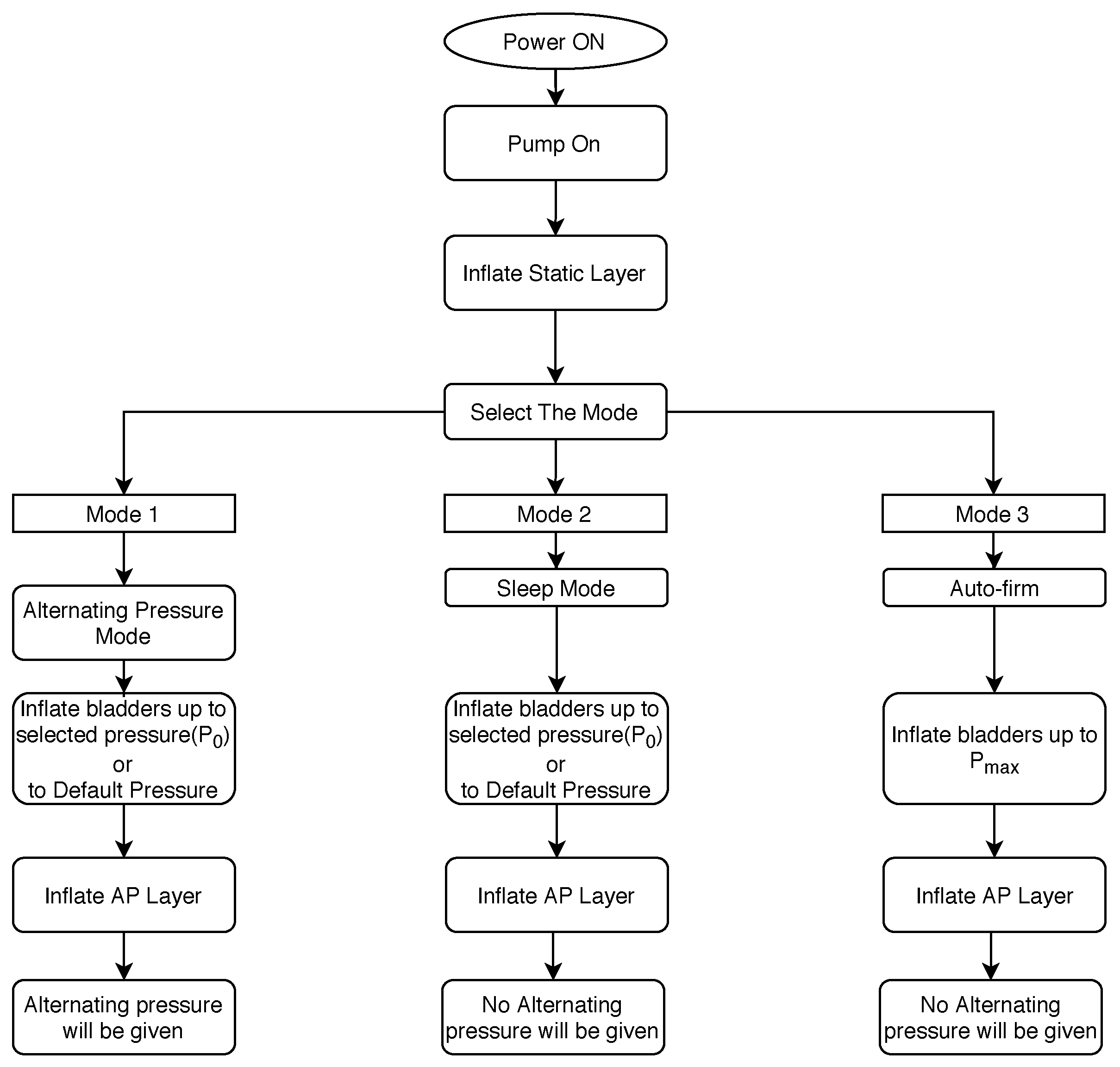
In order to cater various applications and the comfortability of the patient, three modes of operations are identified. They are namely: “Alternating Pressure mode”, “Auto-firm mode” and the “Sleep mode”. For the actuation of these three modes, a control system is designed accordingly. The flow chart shown in
Figure 1 depicts the selection of the above-mentioned modes and its basic functions.
The overall system starts with the “sleep mode”. The sleep mode is used considering the comfortability factor of the patient. During this mode no alternating pressure therapy is given to the patient. The top most air cell layer will be inflated to a static pressure (
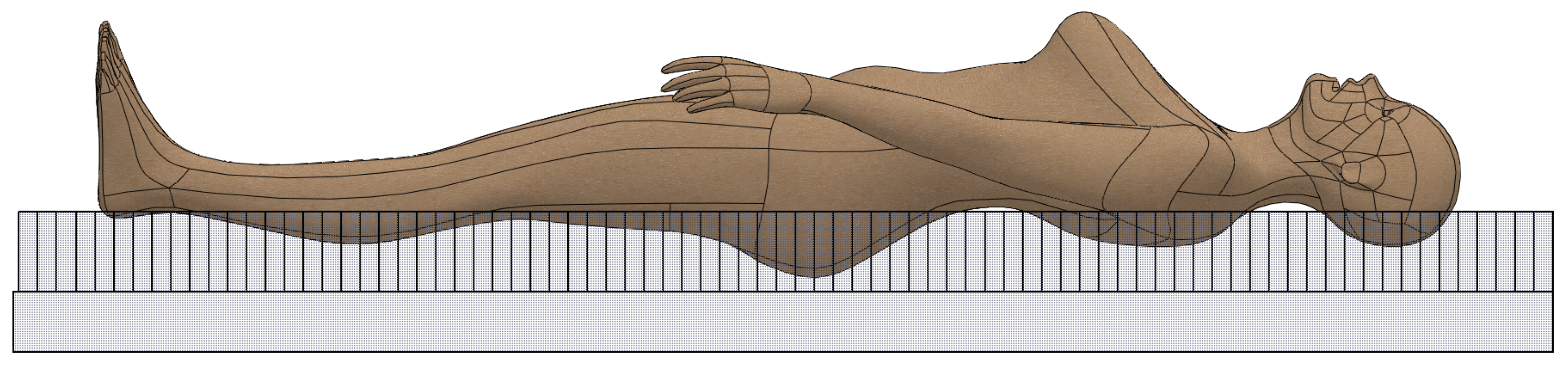
Figure 1). In choosing the required amount of pressure, the caregiver has to enter the weight range of the patient or can simply enter the default mode where the air cells will be inflated to a predefined pressure. These pressures are identified in order to provide the best envelopment of the patient into the overlay which increases the surface pressure helping the reduction of localised high pressure zones (
Figure 2). The sleep mode can be continued considering the comfortability of the patient: when the patient is in actual sleep or if the clinician decides to switch to the alternating pressure mode to provide the pressure therapy.
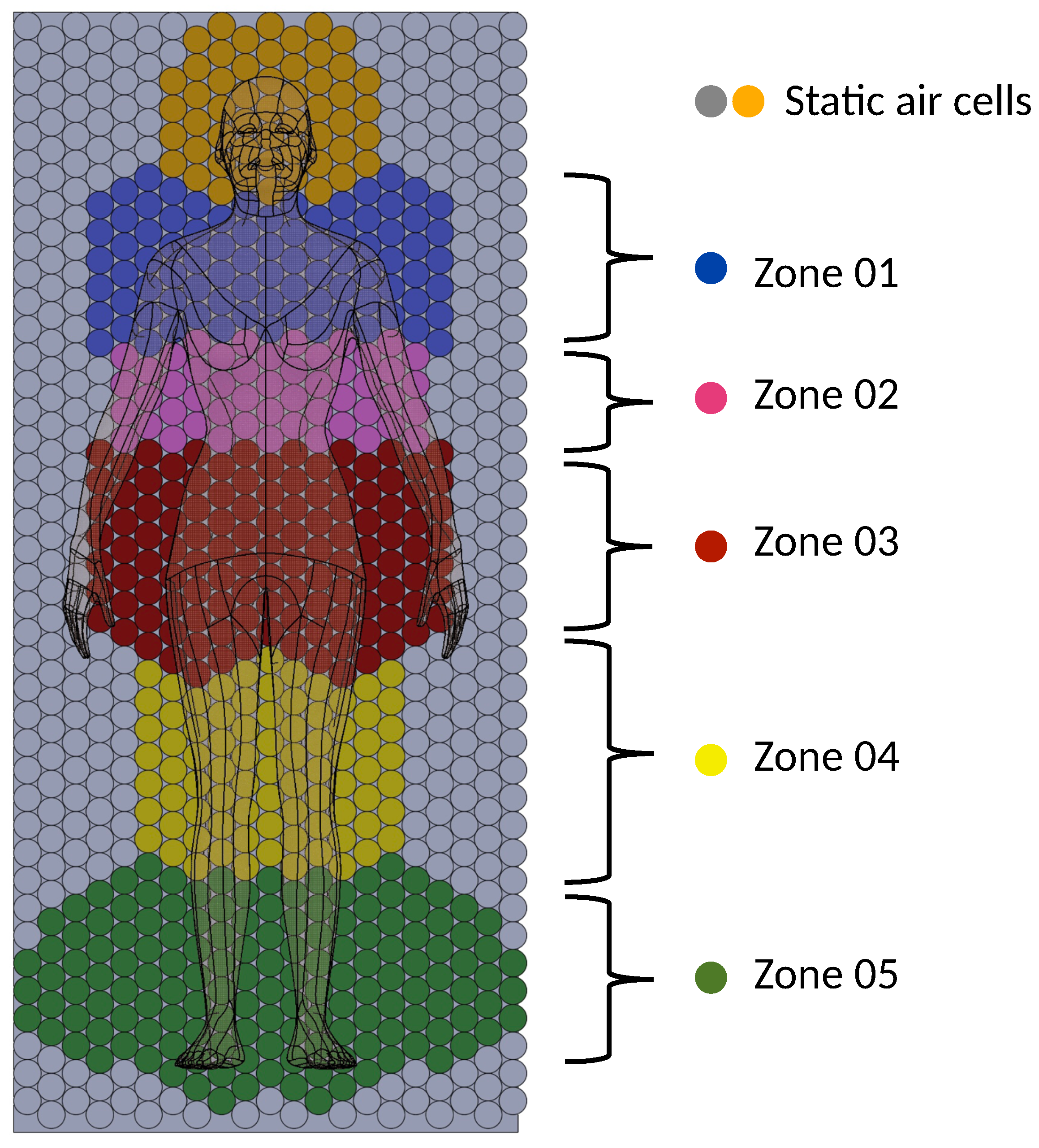
Once the patient is laid onto the overlay, the caregiver can activate the alternating pressure mode where the alternating pressure therapy begins. As mentioned earlier, the high pressure areas of the overlay are identified according to the divided pressure zones of the overlay (
Figure 3) and the overlay would be actuated zone wise. If a zone of the overlay is identified as a high pressure zone, i.e., the pressure is higher than 32 mmHg (the threshold contact pressure for pressure ulceration), that particular zone is actuated with a 1-in-4 predetermined alternating pressure pattern. Each zone of the overlay will be monitored and zones with high pressures will be provided with the alternating pressure therapy.
The auto firm mode is used in treating patients such as repositioning and putting the patient into sitting position. In the auto firm mode, the air cells are pumped into its maximum pressure, and due to the high pressure of the air cells and the firmness provided by the overlay, the motion of the patient due to the envelopment will be minimised. This makes it easier for the caregiver to handle the patient while preventing the patient bottoming out. However, due to the the high pressures and the rigid like structure this mode, high pressure zones can be formed. Therefore it is advised to use this mode for a minimum time possible, and to change into the alternating pressure mode for the pressure relieving.
3. Results and Discussion
As mentioned earlier, for the ease of actuation and the effectiveness of the pressure therapy, the overlay is divided into various zones (
Figure 3). It is evident that the pressure ulceration is more prominent in bony areas: such as the heel, sacrum, elbows, etc. [
1]. The zones of the overlay are divided identifying these high probability zones of pressure ulceration. Furthermore, the size of the zones are identified considering the movement of the body part and the surface area of the specific body part in contact with the overlay (i.e., leg/arm movements, head movements). To increase the efficiency of the overlay, the rest of the air cells (marked in grey colour in
Figure 3), which have less probability of contacting the patient’s body, are kept at a constant pressure as predefined in the selected mode. In many customer reviews of the current products available in the market, it is mentioned that the alternating pressure therapy given to the head of the patient causes discomfort. Hence, to reduce the factor of discomfort in the current design, the zone where the head is positioned is inflated only to a constant pressure according to the mode selected.
Therefore, except in the zones coloured in Orange and Grey in the
Figure 3, if high pressures greater than 32 mmHg are observed in the other zones (i.e., the zones 01, 02, 03, 04 and 05 in
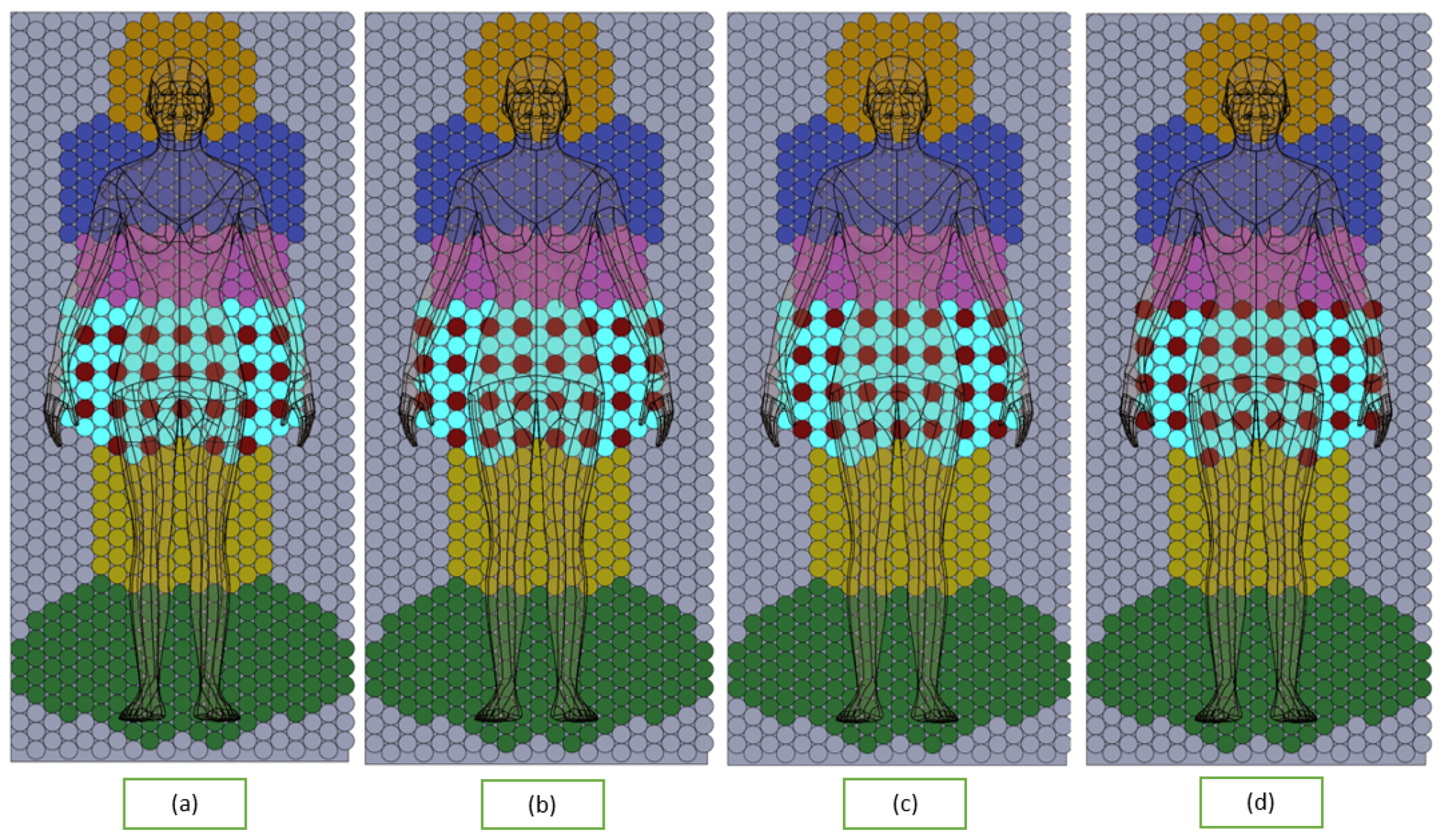
Figure 3) of the overlay, the particular zone will be actuated with an alternating pressure pattern. The pressure pattern of the overlay is a 1-in-4 pressure pattern, where all the cells in a zone is divided into four parts and in one instance of the pressure therapy, three parts of the air cells will be inflated while the remaining part of air cells will be deflated giving no contact with the human body. The inflating/deflating pressure pattern will be predefined. The pressure pattern of the zones will be a randomised pattern rather than a regular pattern which is proven to be very effective [
11]. An example of the sequence of the pressure pattern in zone 3 is shown in
Figure 4.
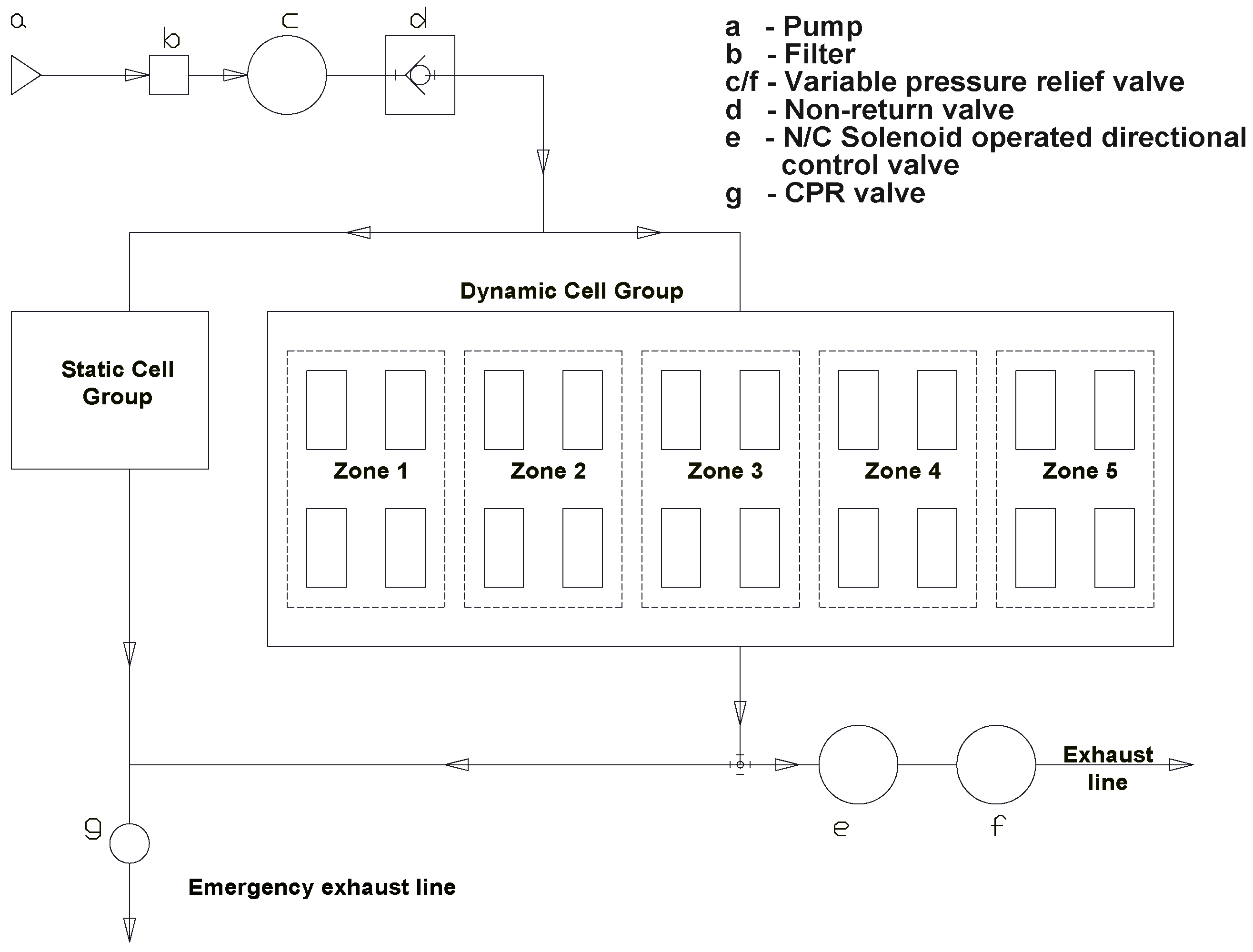
Figure 5 shows the basic schematic of the designed control system. The static cell group will be given the predefined static pressure directly from the pump. As mentioned earlier, the dynamic or the top most layer of air cells are divided into pressure zones. In order to provide the pressure therapy, to inflate and deflate the air cells, the air cells in each of the pressure zones are then divided into four sets of air cells as shown in
Figure 5. Each of these sets of air cells are actuated separately and the actuation process is depicted in
Figure 4.
To pump air to the two layers of air cells, the static cell group and dynamic cell group, an air pump should be used which can pressurise air up to 8000 Pa with an air flow rate around 20 CFM. A paper air filter (depicted in b in
Figure 6) is used to minimise dust and foreign particles entering the system. The variable pressure control valve
c of the pneumatic circuit in
Figure 6 actuates the internal pressure of the air cells according to the mode selected by the customer. In addition to that, this valve eliminates the air flow fluctuations of the flow line. Another issue is that when the patient lies on the overlay, the air cells get pressurised forcing an air flow back to the pump. In order to overcome this issue, a nonreturn valve
d is installed in the pneumatic circuit. The air flow then will be divided into two paths, the air flow into the static cell group and the other to the dynamic cell group as depicted in
Figure 6.
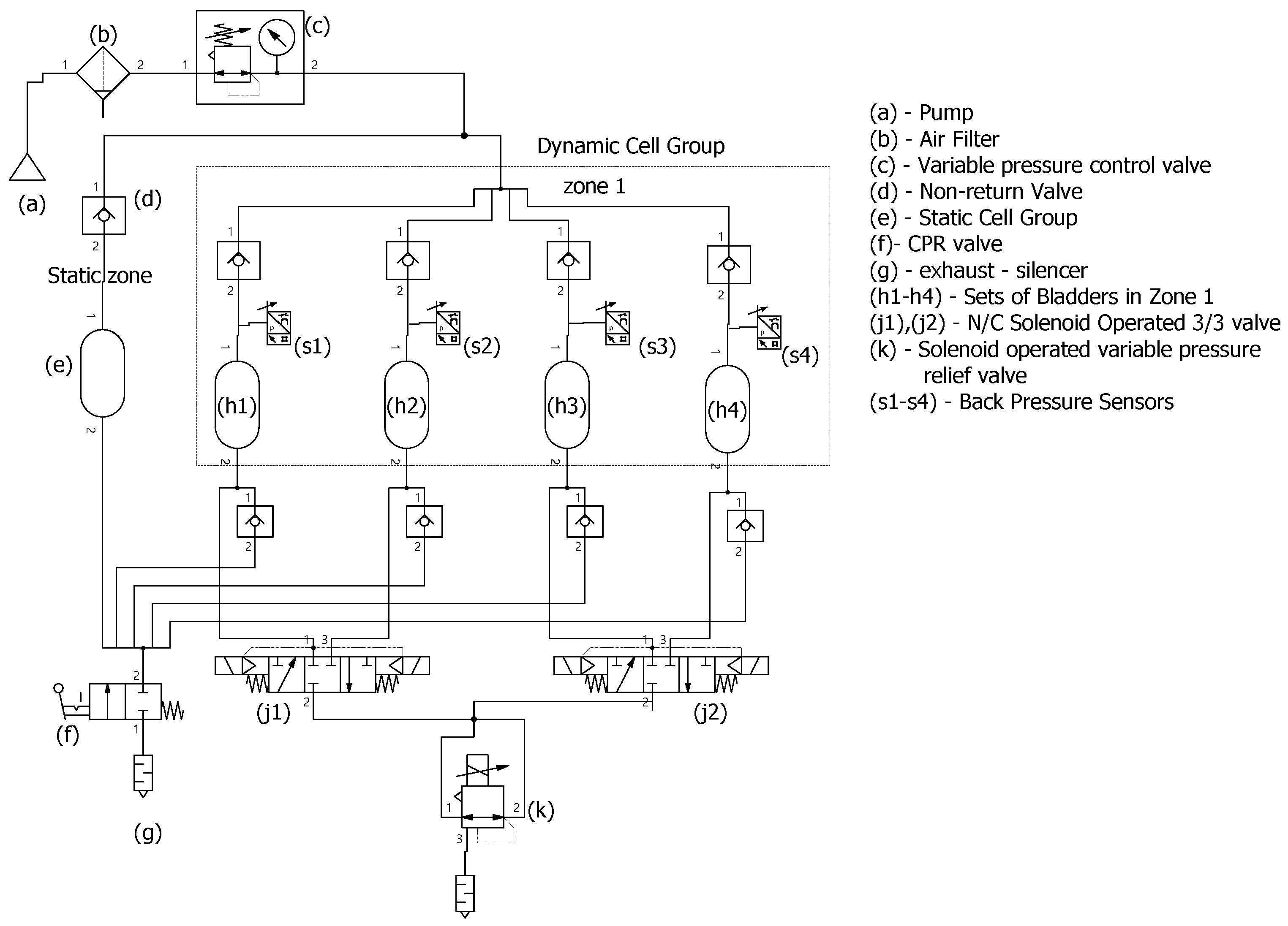
Referring to the pressure sequence given in
Figure 4, the actuation of zone 1 of the dynamic cell group will be as follows. Each of the four air cell sets (h1, h2, h3, h4) of the zone 1 are comprised of individual back pressure sensors to sense real time back pressure. In this whole system, the inflation flow is continuously supplied by the pump. In order to provide the alternating pressure therapy, deflation process of the air cell is achieved by maintaining a higher exhaust flow rate than the inflation flow rate. Considering the particular deflation of the air cell set “h1”, the normally closed solenoid operated 3/3 valve
j1 will be actuated while the controlling the exhaust flow rate using the solenoid operated variable pressure relief valve
k as depicted in
Figure 6. In order to control the pressure pattern, cycle time of inflation and deflation and the initial pressure provided, the solenoid operated valves and pressure regulators are controlled by using a microcontroller.
In order to rapidly deflate both the static cell group and the dynamic cell group completely, for emergency purposes and for the portability of the overlay, the manually operated CPR valve (f) is included in the pneumatic circuit used.

 ,
, 


