Proceeding Paper

Assembly and Characterization of a DE Actuator Based on Polymeric Domes as Biasing Element †

1
Intelligent Material Systems Laboratory, Department of Systems Engineering, Department of Materials Science and Engineering, Saarland University, 66121 Saarbruecken, Germany
2
Department of Sensors and Thin Films, University of Applied Sciences of Saarland, Goebenstraße 40, 66117 Saarbruecken, Germany
*
Author to whom correspondence should be addressed.
Presented at the First International Electronic Conference on Actuator Technology: Materials, Devices and Applications, 23–27 November 2020; Available online: https://iecat2020.sciforum.net/.
Proceedings 2020, 64(1), 24; https://doi.org/10.3390/IeCAT2020-08490
Published: 20 November 2020

Abstract

:
Dielectric elastomer (DE) technology opens up the possibility of constructing novel lightweight and energy-efficient mechatonic systems, whose design can be tailored to several applications. Numerous types of DE actuator (DEA) configurations, capable of high-force, high-speed, and high-stroke, have been presented in the recent literature. One relevant example is represented by membrane DEAs. This type of actuator consists of a DE film pre-loaded with a mechanical bias. In case the biasing element shows a negative slope (i.e., stiffness) in its force-displacement characteristic, the stroke of the resulting DEA can be significantly magnified. Conventional negative-stiffness biasing systems are based on pre-compressed metal beams, thus they appear as unsuitable for miniaturization to the meso- or micro-scale, as well as for the design of completely flexible actuators for wearable and soft robotics applications. To overcome those issues, a new, novel, full polymer-based DEA configuration is introduced in this work. The core element is the biasing system, which is based on a compliant silicone dome. This type of bias presents a negative stiffness region within its mechanical characteristic; thus, it can serve as a flexible alternative to metal-based biasing systems. It will be shown how the force-displacement characteristic of the dome can be geometrically tuned to match the ones of the DE. In this way, a large actuation stroke can be achieved with a full polymer-based design. After discussing system design and manufacturing, the actuator element is assembled. Finally, experimental stroke characterization is performed.

1. Introduction

Microelectromechanical systems (MEMS) are currently omnipresent in our everyday lives. Their use ranges from medical to consumer applications, and new fields of applications are found regularly. Relatively new application fields, such as wearables and soft robotics, can provide many benefits in a number of industrial, medical, as well as consumer-related applications [1,2]. Key features of wearable devices and soft robots are their flexibility and compliance. Such features, however, are usually difficult to achieve with conventional MEMS technologies. Dielectric elastomer (DE) transducers, however, can serve as a basis for the development of highly flexible actuators and sensors [3,4,5,6,7,8]. Some of the most important and attractive features of DE membranes are high energy density, high strain, lightweight, and low-cost [9,10,11]. In order to use a DE membrane to design a large-stroke actuator, it needs to be pre-loaded with a mechanical biasing system. Such a bias can consist of a linear spring or, eventually, a so-called "negative stiffness bias spring". While the former is characterized by an inherent design simplicity, the latter allows to remarkably increase the performance in terms of stroke and work output. A negative stiffness bias element can be realized, for instance, by pre-compressing a thin metal beam [12]. By using this design solution, a variety of large-stroke actuators have been developed, such as contactors [13] or pumps [14]. Most of these actuator configurations, however, implement the negative stiffness feature via metallic biasing elements (such as springs or metal beams). Despite being effective, these elements are characterized by an inherently high stiffness which makes them unsuitable for wearables and soft robots. Furthermore, the stiff structure affects the possibility of miniaturizing such elements.
An alternative and completely flexible solution for generating a negative stiffness bias is represented by polymeric domes [15]. By properly designing the geometry of such elements, their negative stiffness characteristic can be modulated and matched to the one of the DE, thus leading to a large actuation stroke. The goal of this work is to demonstrate the feasibility of such polymeric domes as biasing elements for DEAs. Therefore, the dome geometry and one option of how to change it in order to tune the force-displacement curve of the dome will be described. Furthermore, a new design of a flexible DEA, as well as a possible manufacturing process is presented. A circular out-of-plane DEA is used as a case study for validating the novel bias concept which is characterized in order to compare the performance of the real system to the one predicted by design.
The remainder of this paper is structured as follows. In Section 2, the basic principle of DEs and DEAs is to be explained first, followed by a description of the dome. Overall actuator design and assembly is also discussed. In Section 3, the design is validated by means of experimental results. Finally, in Section 4, concluding remarks are discussed.

2. Methods

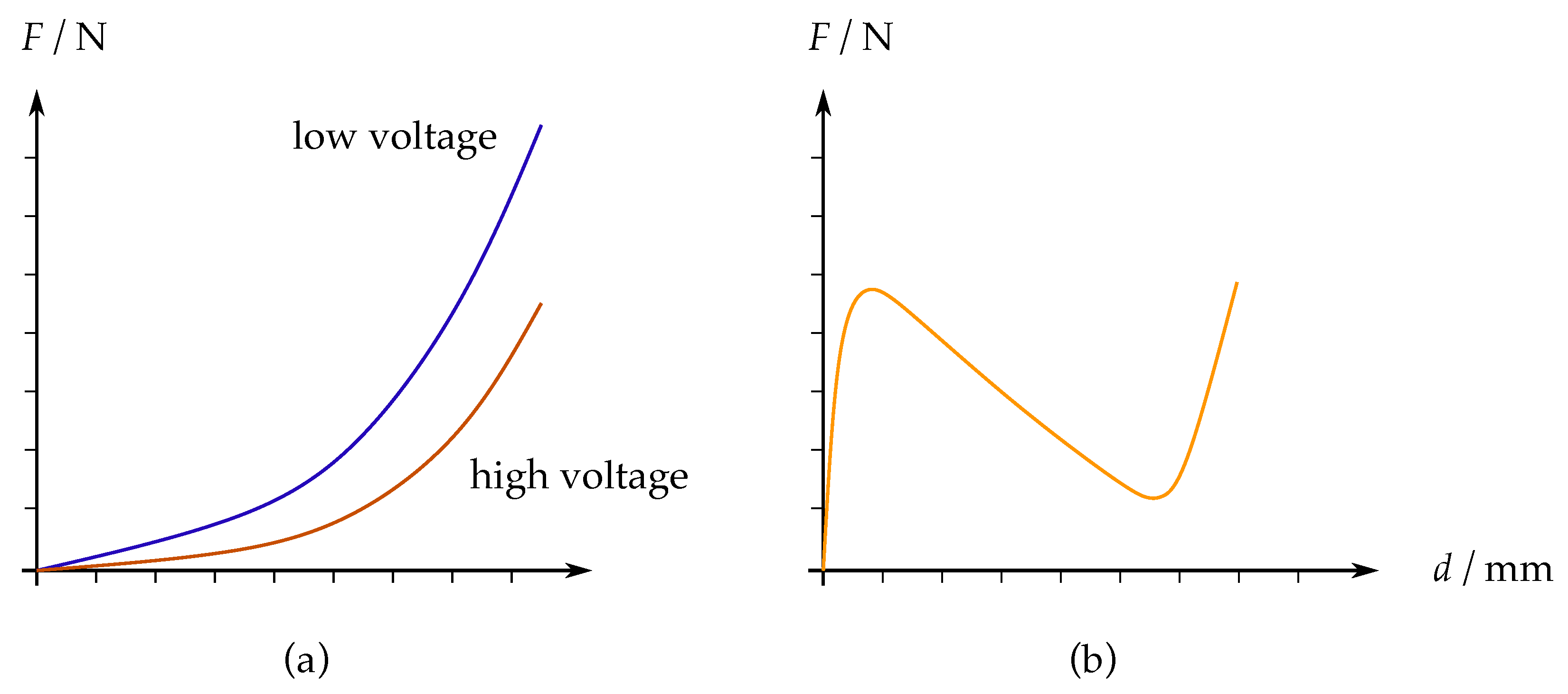
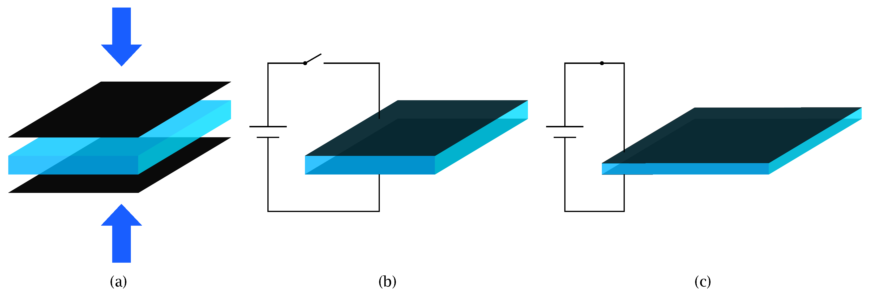
2.1. DE- and DEA-Principle

In order to comprehensively describe the design method of the compliant DEA, as well as its assembling process, the basic operating of DEAs must be explained first. A DEA is based on the combination of two components, that is, the DE-membrane and the biasing system.
The DE membrane consists of a silicone membrane coated with compliant electrodes on both sides, as shown in Figure 1. Electrically, this system represents a capacitor. When a high voltage (on the order of several kV) is applied to the electrodes, the attractive forces among opposing charges on the two electrodes lead to membrane compression. This induces a thickness reduction which, due to the incompressibility of the silicone, results in an area increase.
Due to the high flexibility of DE material, several types of actuator configurations can be constructed. Some examples include strip- [12], cone- [16], or rolled [17] DEAs. Each type of actuator requires a structured and defined electrode geometry, which can be achieved with a screen-printing [18] or sputtering process [19]. The device presented in this work is a cone-DEA, also known as circular out-of-plane DEA (COP-DEA). For this type of actuator, the electrodes are structured as a ring with defined outer- and inner diameter, as shown in Figure 2a. In here, the black ring is the compliant electrode, while the brown parts represent a rigid frame material, that is, epoxy. This particular geometry is able to undergo an out-of-plane deflection, as shown in Figure 2b.
To characterize a particular COP-DEA, a pre-defined out-of-plane deflection can be applied to the center disk while measuring the corresponding force. This characterization can be performed two times, with the DE subject to no voltage and high voltage, respectively. By doing so, two force-displacement curves are obtained. A qualitative sketch of such curves is shown in Figure 3a. In here, it can be seen that the application of a high voltage basically results into a softening of the COP-DEA.
In order to exploit such a membrane for actuation purposes, a biasing system is required. A simple example of a biasing element is represented by a linear spring, which can be pushed against the center part of the circular DE. Once the DE is activated, its stiffness is reduced, as shown in Figure 3. As a result, the compressed spring pushes the membrane further, resulting in a stroke. A more effective biasing element is represented by a negative bias spring (NBS), such as a thin, pre-compressed metal beam. The force-displacement curve of such a type of element exhibits a region of negative stiffness, as shown in Figure 3b. If both DE and bias curves are plotted on the same diagrams, the corresponding intersections reflect the system equilibrium states for unactuated and actuated cases, see Figure 4. Note how the NBS curve in Figure 4 is vertically mirrored in comparison to Figure 3b, since its force is represented with respect to the DE displacement (instead of NBS displacement). The horizontal distance between those two equilibrium points represents the theoretically achievable stroke of the specific system. Based on those curves, the system stroke can then be estimated in a simple graphical way. Note how, once a certain DE is given, the stroke can be optimized by properly designing the NBS curve (e.g., by changing its geometrical and spacing parameters), in such a way that it fits between the two elastomer characteristics. The change in stiffness of the NBS represents, indeed, the key feature which allows to design a large stroke actuator (since it allows to push the two intersection points further apart from each other).

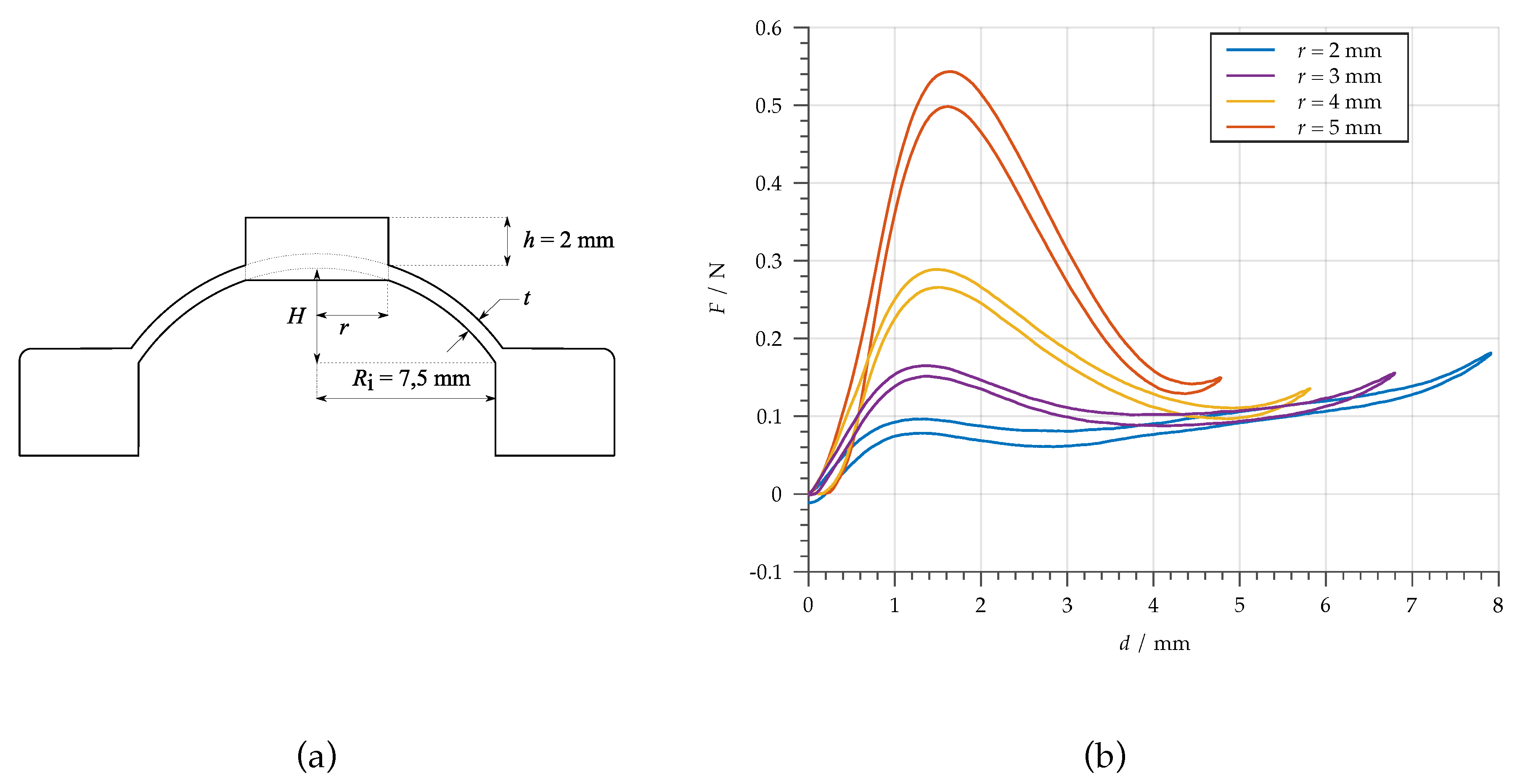
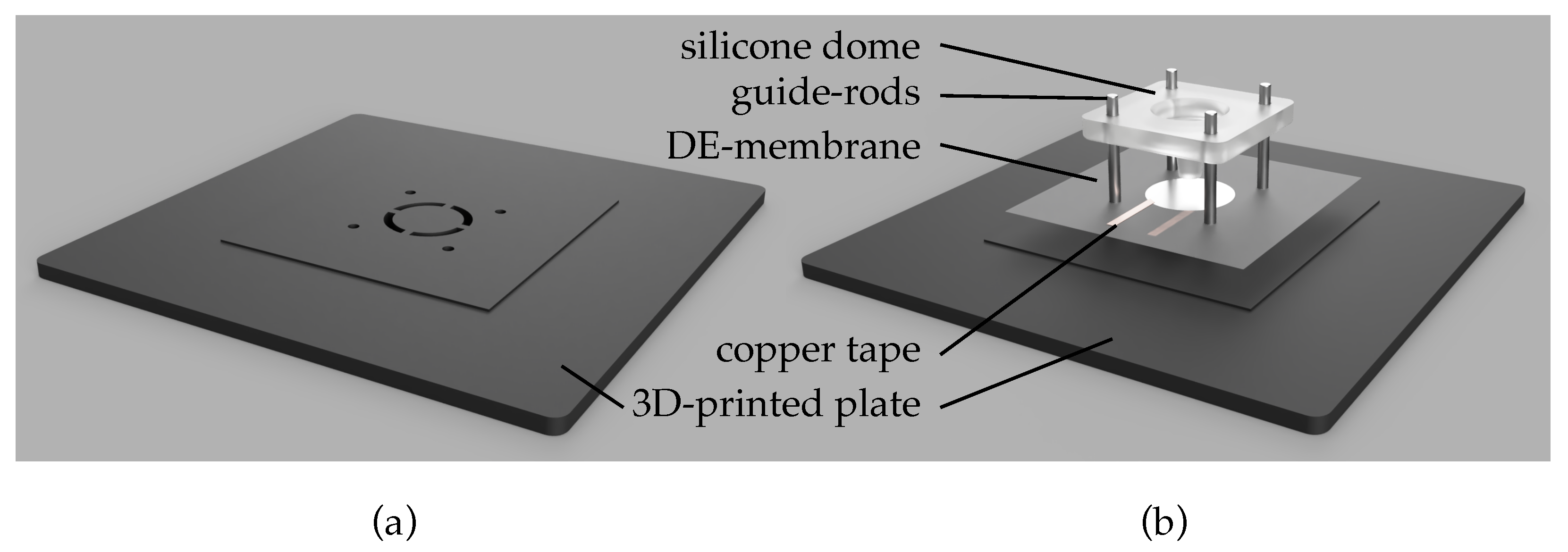
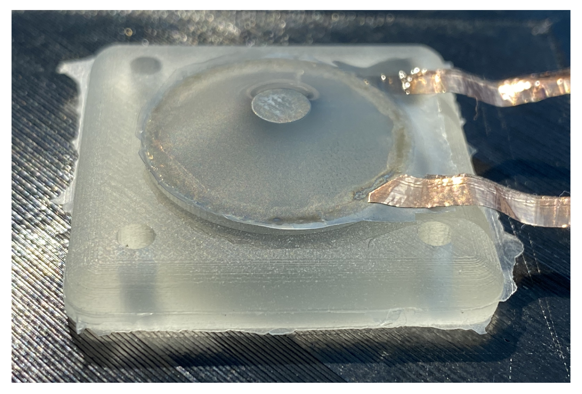
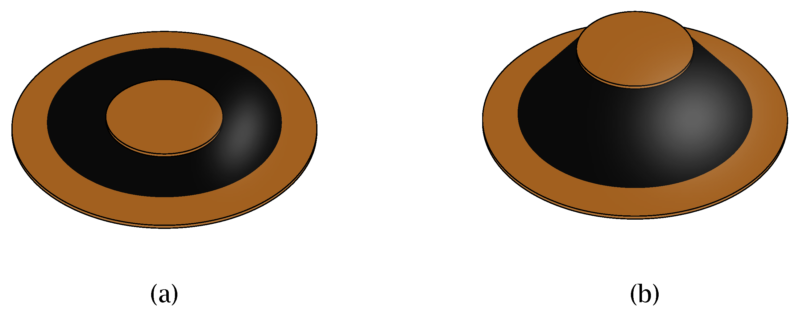
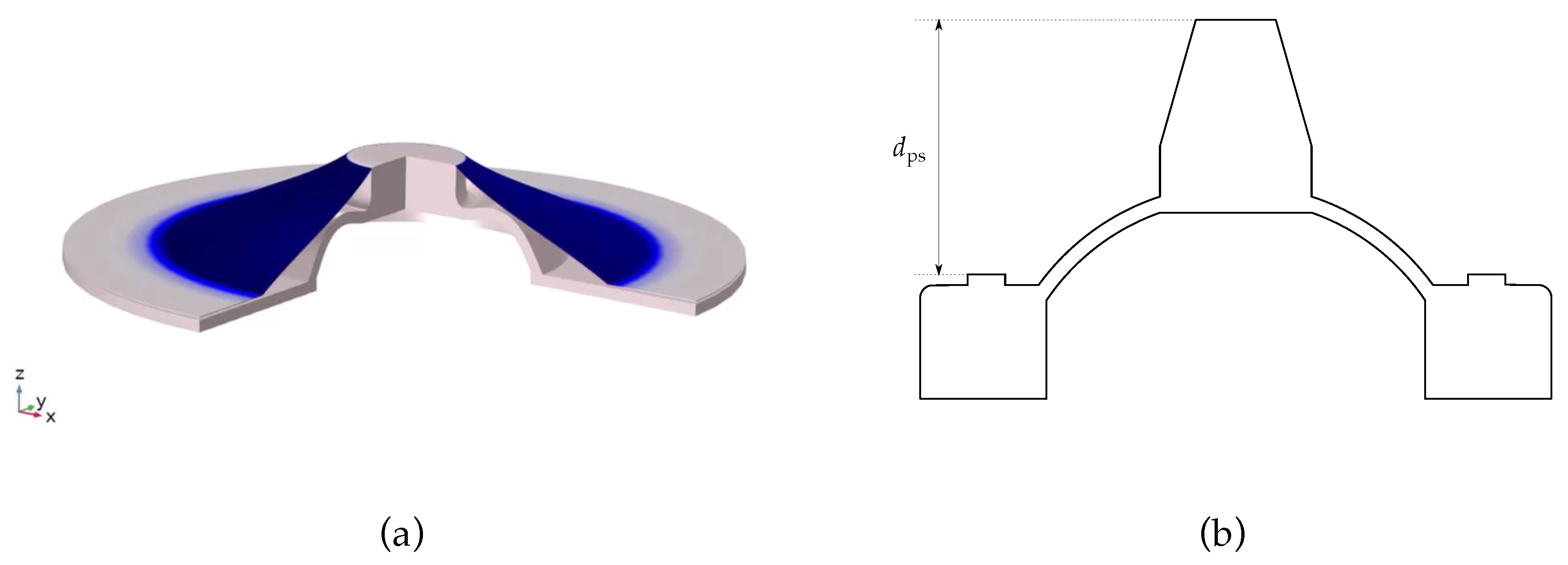
2.2. Design and Assembly of a Flexible Dome-Based DEA

As stated in Section 1, a dome-shaped silicone element will be used in this paper as NBS. In Figure 5a, a sketch of the cross-section of a dome is depicted. The figure illustrates all the relevant geometrical parameters that can be changed in order to influence its force-displacement curve. The domes are manufactured via a casting process of a two-component silicone (ELASTOSIL SILGEL 612EH), by using a 3D-printed mold. Figure 5b shows the measured force-displacement curves of four different dome geometries, all of them having the same wall thickness t = 0.6 mm , the same height H = 4 mm , and the same radius R i = 7.5 mm , but four different values of the flat-top radius r = 2 , 3 , 4 , 5 mm . It can be noted how each curve has a typical NBS shape (cf. Figure 3b), thus confirming the suitability of the polymeric dome as a biasing system for DEAs. Figure 5b also clearly shows the influence of the varied geometry parameter r on the value of the first local force maximum, as well as on the absolute value of the negative slope k. We conclude that r represents an effective parameter which can be used to tune the force-displacement curve of the dome. The hysteresis of the dome curves arise from the viscoelastic behavior of the silicone which is affected by the measuring frequency.
Such kinds of measurements can be used to find an optimal dome geometry, once a DE membrane is given. To check the suitability of the geometry, the force-displacement curve needs to be measured and plotted together with the corresponding DE curves, as illustrated in Figure 4. The optimal value of d p s , representing the pre-stretch between the NBS and the DE (see Figure 4), follows from this graphical design method, and is essential for the manufacturing of a functioning DEA.
To assemble a completely flexible DEA, it is preferable to avoid using any kind of rigid components, such as screws or clamps, which are common in other DEA designs. Clamps are mostly adopted to fix the alignment between the DE and the bias system, while screws can be used to fine-tune the amount of pre-stretch d p s . To omit these components, the silicone bias system and the DE membrane are connected together by using a special glue for silicone materials. The pre-stretch d p s is then determined by properly designing the silicone dome. Figure 6a shows the scheme of the assembly. In this configuration, the outer edge of the DE membrane is glued directly onto the flat area of the silicone dome. The pre-stretch d p s is then determined by the overall height of the dome, measured from the level where the membrane is glued to the top of the dome. This means that the amount of pre-stretch has to be determined before manufacturing the dome, because it is given by the overall height of the dome, and thus cannot be fine-tuned after the membrane has been attached. Parameter d p s can be eventually changed by adding a cone-shaped part on top of the original dome geometry, as shown is Figure 6b. The bottom radius of this cone corresponds to the value of the flat top radius, while the top radius has to match the inner radius of the DE electrode geometry.
A schematic depiction of the assembling is shown in Figure 7b, based on a 3D-printed plate (Figure 7a). In the first step of the process, copper tape is glued on both electrodes of the DE, and used for electrical contacting. In the second step, the DE membrane is centered on the plate. The patterned holes correspond to the electrode geometry of the DE, and are used for an easier alignment of the membrane with respect to the plate. The subsequent step consists of applying the glue on the silicone dome. It has an enhanced ring (see Figure 6b), whose radius corresponds to the outer radius of the electrode, and serves as a defined gluing edge. Then, the dome is glued to the DE membrane by using guide rods, in order to achieve a more accurate positioning. Finally, the excess unglued membrane material is removed.

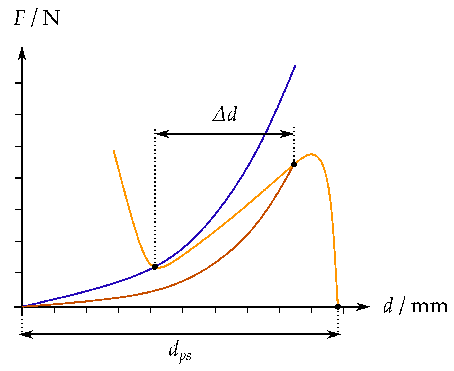
3. Results and Discussion

Figure 8 shows a picture of a dome manufactured according to the previously described process. The basis of the DE is a silicone film 50 μ m thick (ELASTOSIL® 2030), and it has an outer diameter of around 20 mm and an inner diameter of 5 mm . The electrodes each consist of a 10 nm layer of Nickel, which is sputtered on the 37,5 % biaxially pre-stretched silicone film. After sputtering, the pre-stretch is released, and the electrodes shows the above described geometry.
In order to measure the experimental stroke performance, and to compare this value to the predicted one, the force-displacement curves of both the DE membrane and dome must be measured prior to the assembly. The curves are then plotted in a similar way to Figure 4. This diagram is then used to determine the suitable amount of pre-stretch d p s , by shifting the starting point of the dome curve until it matches the gap between the DE curves. Figure 9 shows the resulting graph. The obtained value for d p s is 9.1 mm , and has to be set according to the sketch in Figure 6a. From the intersections between the NBS and the DE curves, the theoretically achievable stroke of the actuator is Δ d 3.24 mm .
To compare the theoretical performance to the one of the assembled actuator, the stroke is measured with a laser displacement sensor (Keyence, LK-G87). A sine wave voltage profile, having an amplitude of 3 kV, a frequency of 0.05 Hz, and an offset of 1.5 kV, is applied to the DEA electrodes. During the voltage application, the motion of the DEA inner disk is recorded with the laser displacement sensor. Both voltage signal and measured actuator displacement are shown in Figure 10. The resulting stroke is computed as the difference between the maximum and minimum position in the displacement curve of the laser displacement sensor, and reaches a maximum value of 2.42 mm .
The deviation between the theoretically and measured value of the DEA stroke can have multiple reasons. One possible explanation is due to rate-dependent viscoelastic effects of the DE. In fact, Figure 10b shows that the inner disk was still moving when the voltage was already beginning to decrease at t = 10 s . In addition, the tolerances in the manufacturing process of the dome can also play a significant role, such as a possible deviation from the ideal value of d p s . Nevertheless, the obtained result appears, overall, as satisfactory, since a large-deformation and fully-polymeric DEA has been effectively obtained.

4. Conclusions

In this work, we presented a novel approach for the assembly of a completely flexible and large stroke DEA system. The method is based on exploiting three-dimensional polymeric domes as biasing elements for DE membrane actuators. The novel bias was manufactured via a silicone-casting process. It was shown that, by properly tailoring geometry of the dome, it is possible to match the force-displacement curves of bias and DE. In this way, a large actuation stroke is achieved. Another novelty of this approach is that the final actuator only consists of the dome and the DE membrane, which is directly glued to the base of the dome element. This results in a completely polymeric, and thus flexible actuator, which is suitable for wearable and soft robotic applications. After presenting the system design and manufacturing, we compared the theoretically expected actuator stroke with the experimentally measured one. The measured stroke is smaller than the theoretical value, that is, we obtained a predicted value of 3.24 mm and a measured one of 2.42 mm , based on the actuator having a size of 20 mm in diameter. These differences can be explained by the tolerances of the dome-manufacturing process, as well as by the viscoelastic effects of the DE. In conclusion, we demonstrated the suitability of using silicone domes as a biasing element for dielectric elastomer actuators. In future works, the developed actuator concept will be used to design a cooperative flexible array of micro-sized DEAs.

Funding

The authors gratefully acknowledge the support of the Deutsche Forschungsgemeinschaft (DFG, German Research Foundation) through Priority Program SPP 2206 “Cooperative Multistage Multistable Microactuator Sys-tems” (Projects: RI3030/2-1, SCHU1609/7-1, SE704/9-1).

Abbreviations

The following abbreviations are used in this manuscript:
MEMSMicro electromechanical system
DEDielectric elastomer
DEADielectric elastomer actuator
COP-DEACircular out-of-plane dielectric elastomer actuator
NBSNegative bias spring

References

  1. Banerjee, H.; Tse, Z.T.H.; Ren, H. Soft robotics with compliance and adaptation for biomedical applications and forthcoming challenges. Int. J. Robot. Autom. 2018. [Google Scholar] [CrossRef]
  2. Shintake, J.; Cacucciolo, V.; Floreano, D.; Shea, H. Soft Robot Grippers. Adv. Mater. 2018, 30, 1707035. [Google Scholar] [CrossRef]
  3. Ni, N.; Zhang, L. Dielectric Elastomer Sensors. In Elastomers; IntechOpen: London, UK, 2017. [Google Scholar] [CrossRef]
  4. Henke, E.F.M.; Wilson, K.E.; Anderson, I.A. Entirely soft dielectric elastomer robots. In Proceedings of the Electroactive Polymer Actuators and Devices (EAPAD), Portland, OR, USA, 26–29 March 2017; Volume 10163, p. 101631N. [Google Scholar] [CrossRef]
  5. Xu, D.; Gisby, T.A.; Xie, S.; Anderson, I.A. Scalable sensing electronics towards a motion capture suit. In Proceedings of the Electroactive Polymer Actuators and Devices (EAPAD), San Diego, CA, USA, 11–15 March 2013; Volume 8687, p. 86872L. [Google Scholar] [CrossRef]
  6. Glauser, O.; Panozzo, D.; Hilliges, O.; Sorkine-Hornung, O. Deformation capture via soft and stretchable sensor arrays. ACM Trans. Graph. 2019, 38. [Google Scholar] [CrossRef]
  7. Hill, M.; Rizzello, G.; Seelecke, S. Development and experimental characterization of a pneumatic valve actuated by a dielectric elastomer membrane. Smart Mater. Struct. 2017, 26. [Google Scholar] [CrossRef]
  8. Anderson, I.A.; Gisby, T.A.; McKay, T.G.; O’Brien, B.M.; Calius, E.P. Multi-functional dielectric elastomer artificial muscles for soft and smart machines. J. Appl. Phys. 2012, 112. [Google Scholar] [CrossRef]
  9. Kornbluh, R.D. Shape control of large lightweight mirrors with dielectric elastomer actuation. Proc. SPIE 2003, 5051, 143–158. [Google Scholar] [CrossRef]
  10. Godaba, H.; Foo, C.C.; Zhang, Z.Q.; Khoo, B.C.; Zhu, J. Giant voltage-induced deformation of a dielectric elastomer under a constant pressur. Appl. Phys. Lett. 2014, 105, 112901. [Google Scholar] [CrossRef]
  11. Wang, Y.; Zhu, C.; Pfattner, R.; Yan, H.; Jin, L.; Chen, S.; Molina-Lopez, F.; Lissel, F.; Liu, J.; Rabiah, N.; et al. A highly stretchable, transparent, and conductive polymer. Sci. Adv. 2017, 3, e1602076. [Google Scholar] [CrossRef] [PubMed]
  12. Hau, S.; Bruch, D.; Rizzello, G.; Motzki, P.; Seelecke, S. Silicone based dielectric elastomer strip actuators coupled with nonlinear biasing elements for large actuation strains. Smart Mater. Struct. 2018, 27. [Google Scholar] [CrossRef]
  13. Linnebach, P.; Simone, F.; Rizzello, G.; Seelecke, S. Development, manufacturing, and validation of a dielectric elastomer membrane actuator–driven contactor. J. Intell. Mater. Syst. Struct. 2019, 30, 636–648. [Google Scholar] [CrossRef]
  14. Mohd Ghazali, F.A.; Mah, C.K.; AbuZaiter, A.; Chee, P.S.; Mohamed Ali, M.S. Soft dielectric elastomer actuator micropump. Sens. Actuators A Phys. 2017, 263, 276–284. [Google Scholar] [CrossRef]
  15. Madhukar, A.; Perlitz, D.; Grigola, M.; Gai, D.; Jimmy Hsia, K. Bistable characteristics of thick-walled axisymmetric domes. Int. J. Solids Struct. 2014, 51, 2590–2597. [Google Scholar] [CrossRef]
  16. Hau, S.; Rizzello, G.; Seelecke, S. A novel dielectric elastomer membrane actuator concept for high-force applications. Extrem. Mech. Lett. 2018, 23, 24–28. [Google Scholar] [CrossRef]
  17. Zhang, R.; Lochmatter, P.; Kunz, A.; Kovacs, G. Spring roll dielectric elastomer actuators for a portable force feedback glove. In Proceedings of the Smart Structures and Materials 2006: Electroactive Polymer Actuators and Devices (EAPAD), San Diego, CA, USA, 26 February–2 March 2006. [Google Scholar] [CrossRef]
  18. Fasolt, B.; Hodgins, M.; Rizzello, G.; Seelecke, S. Effect of screen printing parameters on sensor and actuator performance of dielectric elastomer (DE) membranes. Sens. Actuators A Phys. 2017, 265, 10–19. [Google Scholar] [CrossRef]
  19. Hubertus, J.; Fasolt, B.; Linnebach, P.; Seelecke, S.; Schultes, G. Electromechanical evaluation of sub-micron NiCr-carbon thin films as highly conductive and compliant electrodes for dielectric elastomers. Sens. Actuators A Phys. 2020. [Google Scholar] [CrossRef]
Figure 1. (a) Structure of a dielectric elastomer membrane, which is a silicone membrane that is coated with a compliant electrode material (black) on both sides. (b,c) show the basic effect of a DE: When applying a high voltage, the electrodes attract each other due to the electrostatic force, and lead to a geometry change.
Proceedings 64 00024 g001
Figure 2. (a) Undeflected circular out-of-plane DEA (COP-DEA). (b) Desired movement of the inner disk of the DE, when a high voltage is applied.
Proceedings 64 00024 g002
Figure 3. (a) Schematic force-displacement curves of a single COP-DEA. The blue curve refers to the low voltage state, while the red one refers to a high voltage state. (b) Schematic force-displacement curve of a negative bias spring.
Proceedings 64 00024 g003
Figure 4. Schematic force-displacement curve of an assembled DE. The NBS- curve has to be mirrored, because it is working against the DE membrane.
Proceedings 64 00024 g004
Figure 5. (a) Cross-sectional sketch of the dome-geometry. (b) Measured force-displacement curves of four domes, each one corresponding to a different value of r.
Proceedings 64 00024 g005
Figure 6. (a) Scheme of the flexible DEA assembly. (b) Sketch of the dome geometry that accounts for the pre-stretch d p s .
Proceedings 64 00024 g006
Figure 7. (a) 3D-printed alignment plate. (b) Complete schematic assembling procedure.
Proceedings 64 00024 g007
Figure 8. Picture of an assembled DEA, based on a flexible silicone dome as biasing element.
Proceedings 64 00024 g008
Figure 9. Graphical design solution based on measured force-displacement curves of the DE and a silicone dome. The horizontal distance between the intersections of the respective curves, denoted as Δ d , represents the theoretical stroke of the DEA.
Proceedings 64 00024 g009
Figure 10. (a) Input voltage that is applied to the DE electrodes. (b) Resulting measured stroke of the dome-based DEA. d = 0 mm corresponds to the initial position of the inner disk of the DEA, when no voltage is applied.
Proceedings 64 00024 g010
Publisher’s Note: MDPI stays neutral with regard to jurisdictional claims in published maps and institutional affiliations.

