A Concept Design of an Adaptive Tendon Driven Mechanism for Active Soft Hand Orthosis †


Abstract
:1. Introduction
2. Methods
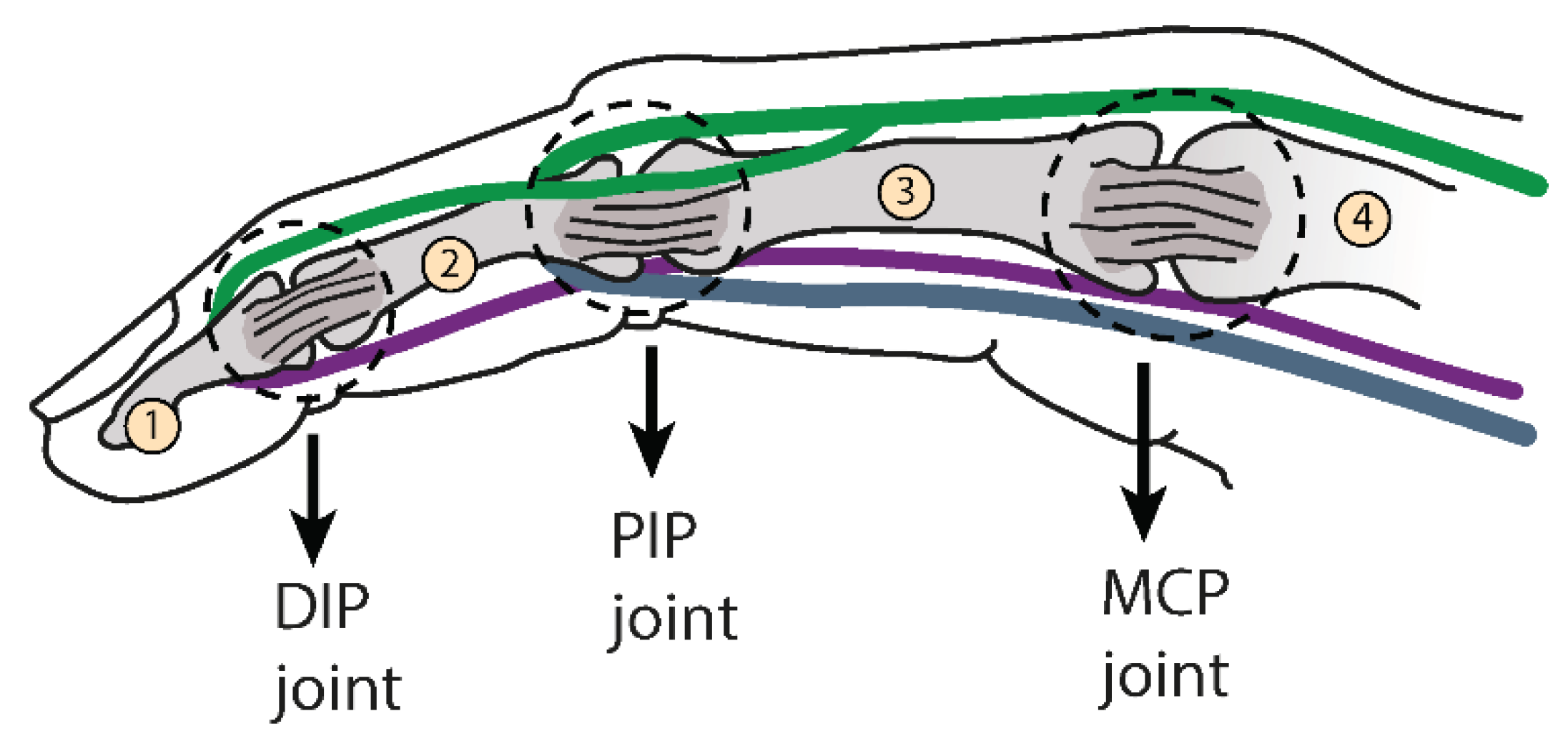
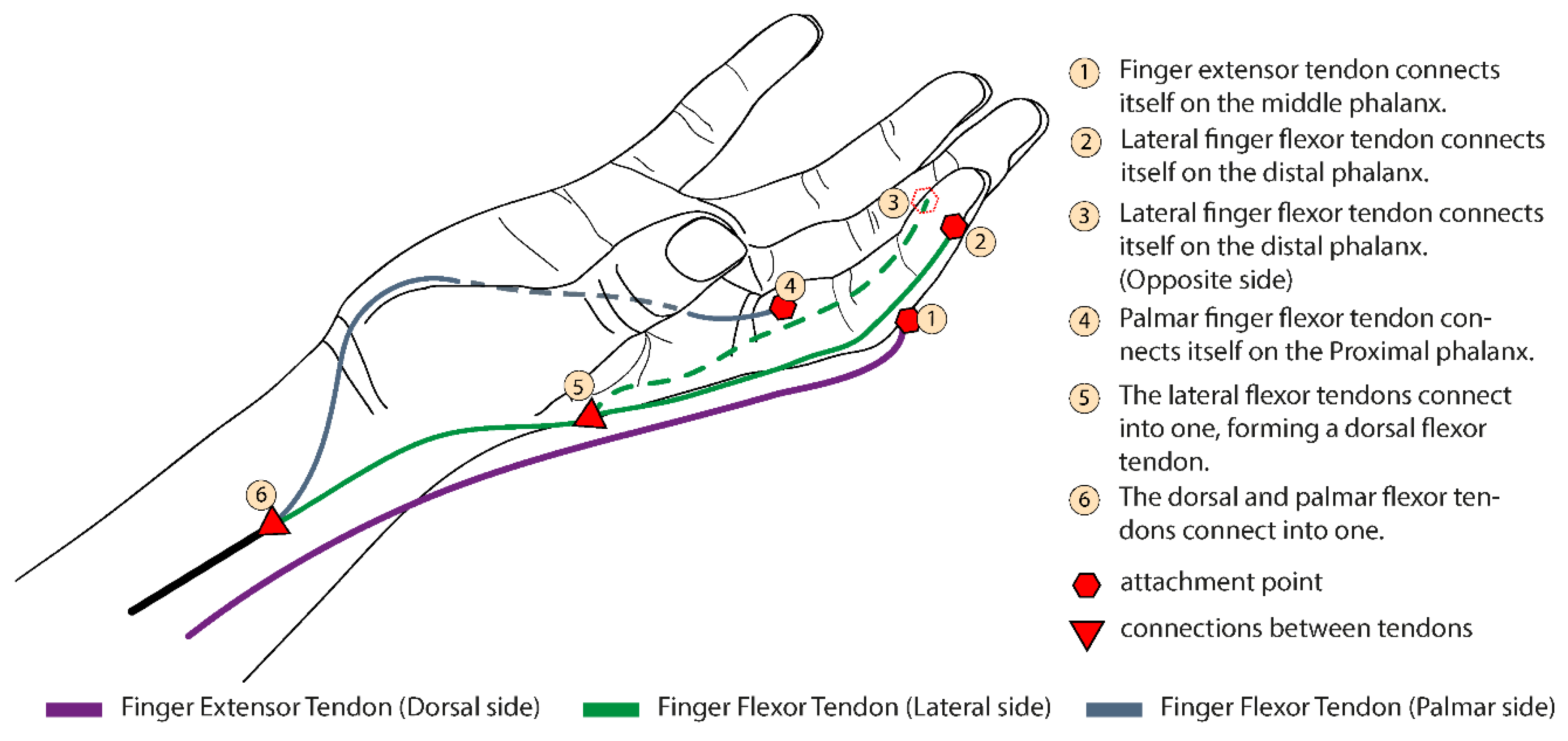
2.1. Biological Inspiration
2.2. Concept
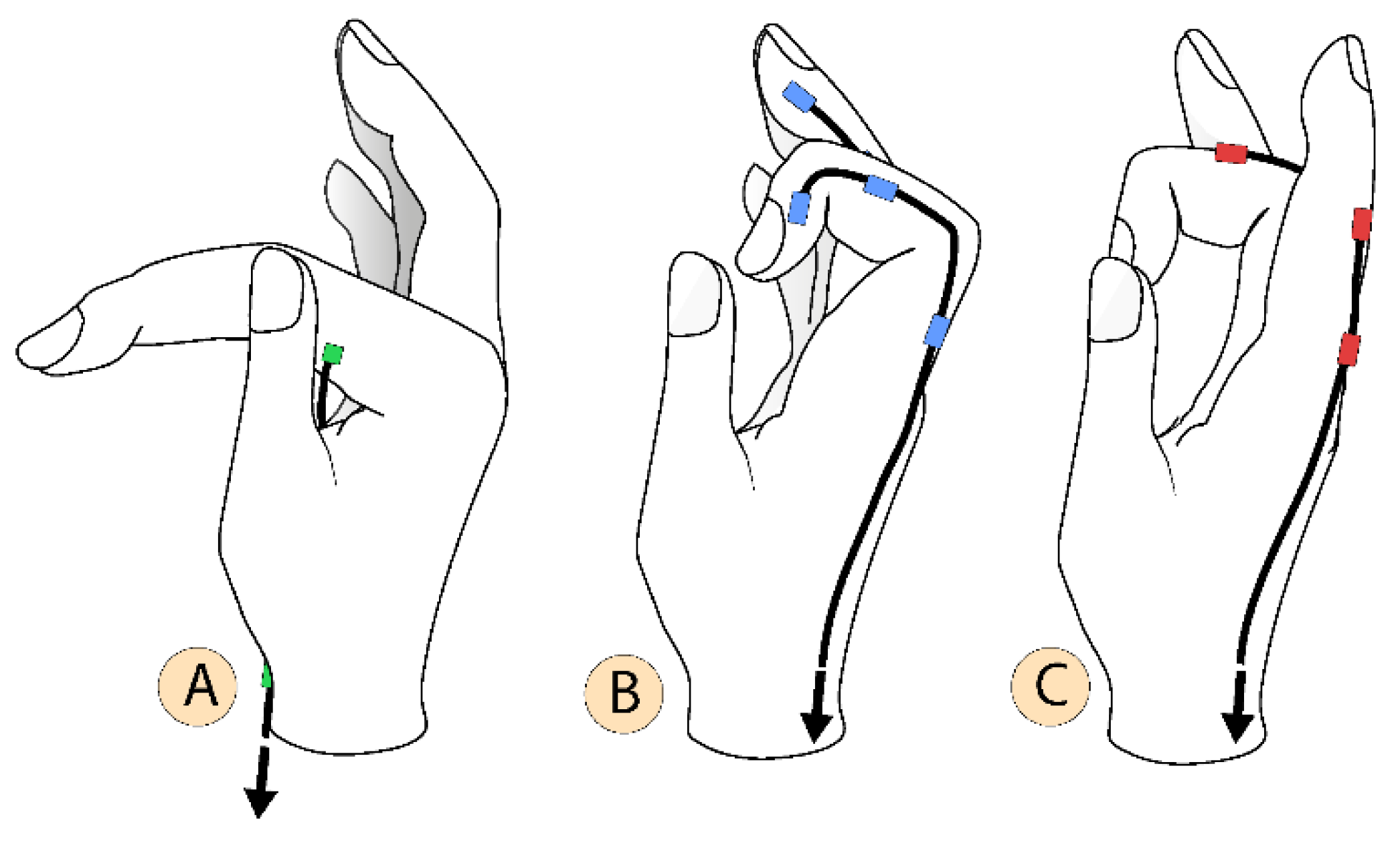
2.3. Multiple Configurations
2.4. Prototype
3. Results and Discussion
4. Conclusions
Acknowledgments
Conflicts of Interest
References
- Nam, H.U.; Huh, J.S.; Yoo, J.N.; Hwang, J.M.; Lee, B.J.; Min, Y.S.; Kim, C.H.; Jung, T.D. Effect of dominant hand paralysis on quality of life in patients with subacute stroke. Ann. Rehabil. Med. 2014, 38, 450–457. [Google Scholar] [CrossRef] [PubMed]
- Masini, M. Estimativa da incidência e prevalência de lesão medular no Brasil. JBNC J. Bras. Neurocir. 2018, 12, 97–100. [Google Scholar] [CrossRef]
- World Health Organization; International Spinal Cord Society. International Perspectives on Spinal Cord Injury; World Health Organization: Geneva, Switzerland, 2013. [Google Scholar]
- Johnson, W.; Onuma, O.; Owolabi, M.; Sachdev, S. Stroke: A global response is needed. Bull. World Health Organ. 2016, 94, 634. [Google Scholar] [CrossRef] [PubMed]
- Baldassin, V. Os Indivíduos com Tetraplegia por Lesão Medular e o uso dos Recursos de Tecnologia Assistiva em Computadores: Uma Abordagem Bioética. Ph.D. Thesis, Universidade de Brasília, Brasília, Brazil, 2017. [Google Scholar]
- Qian, Q.; Hu, X.; Lai, Q.; Ng, S.C.; Zheng, Y.; Poon, W. Early Stroke Rehabilitation of the Upper Limb Assisted with an Electromyography-Driven Neuromuscular Electrical Stimulation-Robotic Arm. Front. Neurol. 2017, 8, 447. [Google Scholar] [CrossRef] [PubMed]
- Díez, J.; BlancoJosé, A.; Catalán, J.M.; Badesa, F.; Lledo, L.; Garcia, N. Hand exoskeleton for rehabilitation therapies with integrated optical force sensor. Adv. Mech. Eng. 2018, 10. [Google Scholar] [CrossRef]
- Stroke, P. Robotic devices and brain–machine interfaces for hand rehabilitation post-stroke. J. Rehabil. Med. 2017, 49, 449–460. [Google Scholar]
- Ryser, F.; Bützer, T.; Held, J.P.; Lambercy, O.; Gassert, R. Fully embedded myoelectric control for a wearable robotic hand orthosis. In Proceedings of the 2017 International Conference on Rehabilitation Robotics (ICORR), London, UK, 17–20 July 2017; pp. 615–621. [Google Scholar] [CrossRef]
- Andrade, R.M.; Sapienza, S.; Bonato, P. Development of a “transparent operation mode” for a lower-limb exoskeleton designed for children with cerebral palsy. In Proceedings of the 2019 IEEE 16th International Conference on Rehabilitation Robotics (ICORR), Toronto, ON, Canada, 24–28 June 2019; pp. 512–517. [Google Scholar] [CrossRef]
- Silveira, A.; Abreu de Souza, M.; Fernandes, B.; Nohama, P. From the past to the future of therapeutic orthoses for upper limbs rehabilitation. Res. Biomed. Eng. 2018, 34, 368–380. [Google Scholar] [CrossRef]
- Abdelhafiz, M.H.; Spaich, E.G.; Dosen, S.; Andreasen Struijk, L.N.S. Bio-inspired tendon driven mechanism for simultaneous finger joints flexion using a soft hand exoskeleton. In Proceedings of the 2019 IEEE 16th International Conference on Rehabilitation Robotics (ICORR), Toronto, ON, Canada, 24–28 June 2019; pp. 1073–1078. [Google Scholar] [CrossRef]
- Laschi, C.; Mazzolai, B.; Cianchetti, M. Soft robotics: Technologies and systems pushing the boundaries of robot abilities. Sci. Robot. 2016, 1, eaah3690. [Google Scholar] [CrossRef] [PubMed]
- Kang, B.B.; Choi, H.; Lee, H.; Cho, K.J. Exo-glove poly ii: A polymer-based soft wearable robot for the hand with a tendon-driven actuation system. Soft Robot. 2019, 6, 214–227. [Google Scholar] [CrossRef] [PubMed]
- Hong, M.B.; Kim, S.J.; Ihn, Y.S.; Jeong, G.; Kim, K. KULEX-Hand: An Underactuated Wearable Hand for Grasping Power Assistance. IEEE Trans. Robot. 2018, 35, 420–432. [Google Scholar] [CrossRef]
- Bützer, T.; Dittli, J.; Lieber, J.; van Hedel, H.J.; Meyer-Heim, A.; Lambercy, O.; Gassert, R. PEXO-A Pediatric Whole Hand Exoskeleton for Grasping Assistance in Task-Oriented Training. In Proceedings of the 2019 IEEE 16th International Conference on Rehabilitation Robotics (ICORR), Toronto, ON, Canada, 24–28 June 2019; pp. 108–114. [Google Scholar]
- Standring, S. Gray’s Anatomy E-Book: The Anatomical Basis of Clinical Practice; Elsevier Health Sciences: Philadelphia, PA, USA, 2015. [Google Scholar]
- Radomski, M.; Latham, C. Occupational Therapy for Physical Dysfunction; Wolters Kluwer Health: Philadelphia, PA, USA; Lippincott Williams & Wilkins: Philadelphia, PA, USA, 2014. [Google Scholar]


| Parameters | Description |
|---|---|
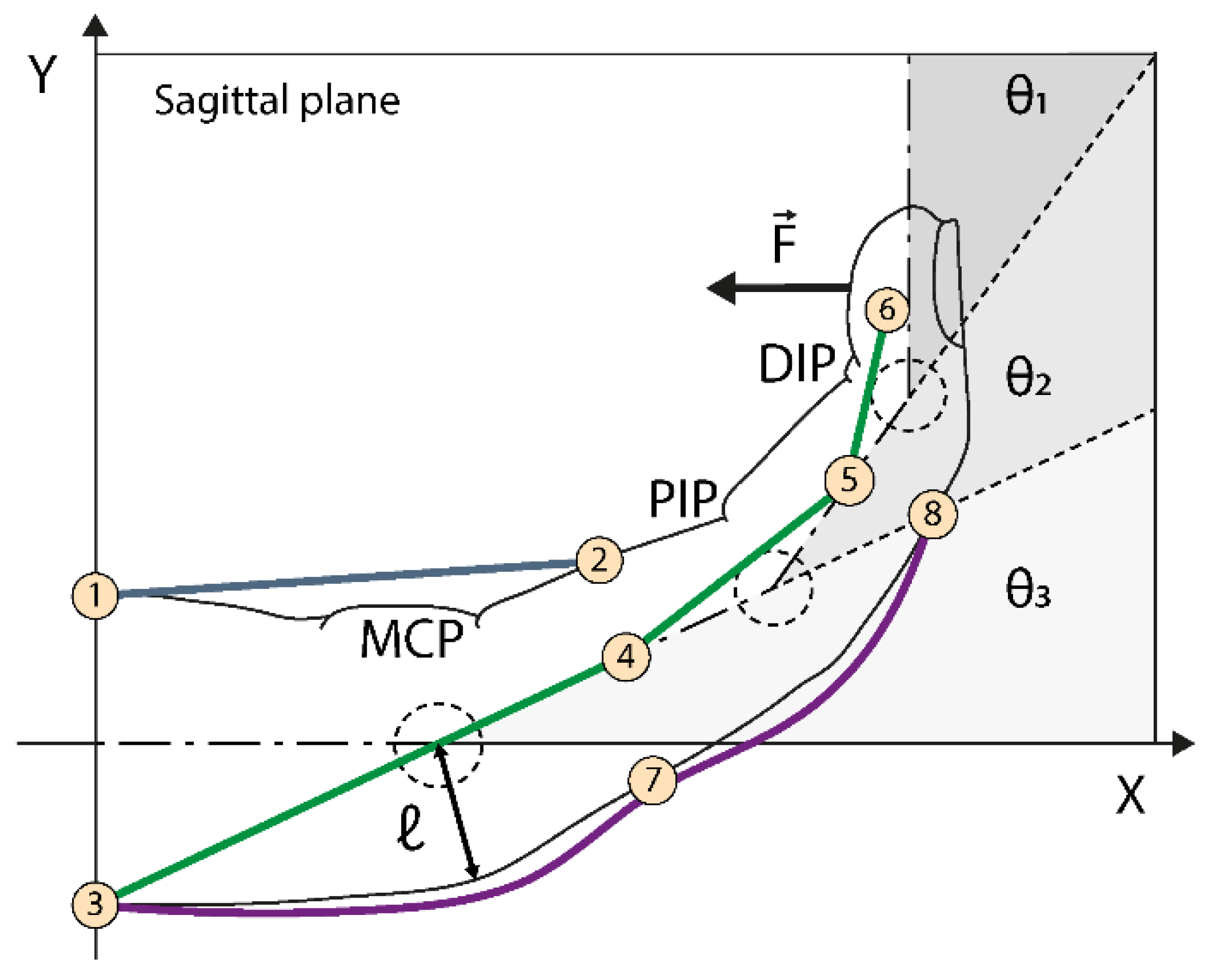
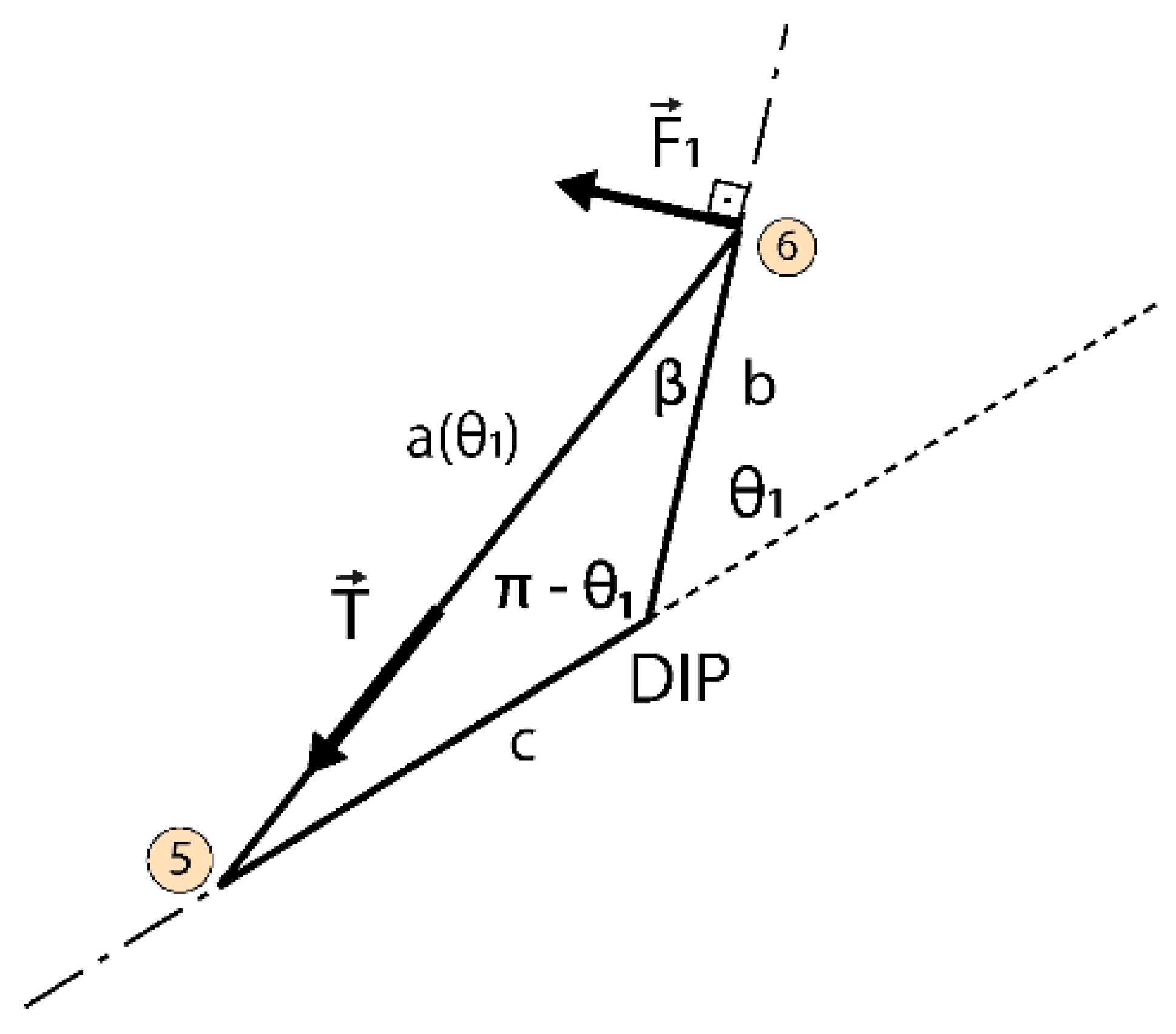
| θ1, θ2, θ3 | MCP, PIP, DIP joint angles |
| ℓ | curvature radius reference, has the average value between each length ℓ for each reference joint |
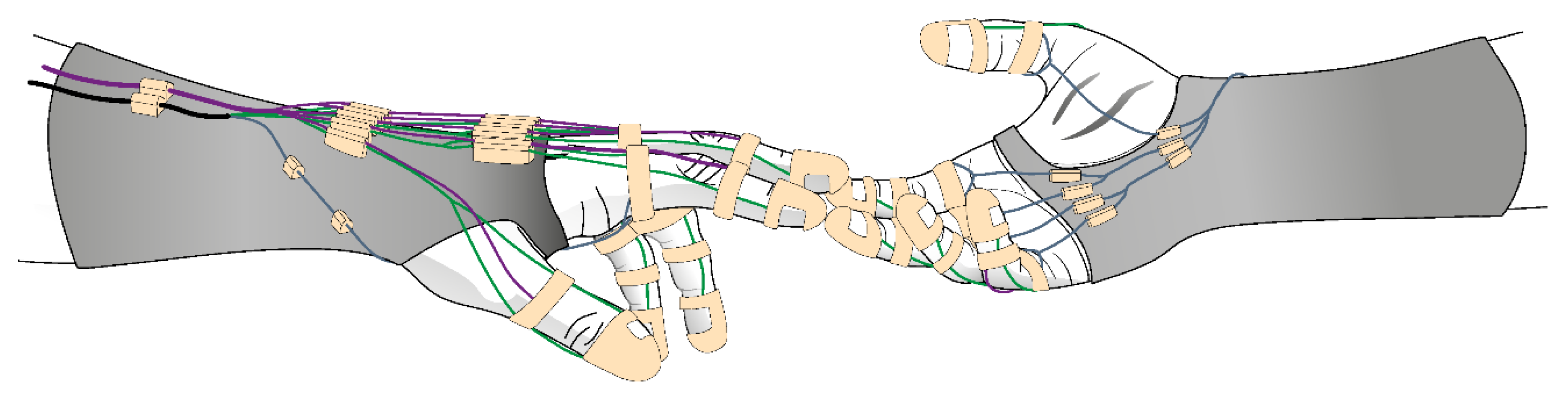
| wires connection points | |
| δr | wire length at the reference position |
| δc | wire length at contraction position |
| δp | length to be wound on the pulley |
| PjMCP | MCP projected on the palmar side |
| Normal force at the distal phalanx | |
| Thread tension |
Publisher’s Note: MDPI stays neutral with regard to jurisdictional claims in published maps and institutional affiliations. |
© 2020 by the authors. Licensee MDPI, Basel, Switzerland. This article is an open access article distributed under the terms and conditions of the Creative Commons Attribution (CC BY) license (https://creativecommons.org/licenses/by/4.0/).
Share and Cite
Lourenço, B.; Neto, V.; Andrade, R.d. A Concept Design of an Adaptive Tendon Driven Mechanism for Active Soft Hand Orthosis. Proceedings 2020, 64, 21. https://doi.org/10.3390/IeCAT2020-08504
Lourenço B, Neto V, Andrade Rd. A Concept Design of an Adaptive Tendon Driven Mechanism for Active Soft Hand Orthosis. Proceedings. 2020; 64(1):21. https://doi.org/10.3390/IeCAT2020-08504
Chicago/Turabian StyleLourenço, Bruno, Vitorino Neto, and Rafhael de Andrade. 2020. "A Concept Design of an Adaptive Tendon Driven Mechanism for Active Soft Hand Orthosis" Proceedings 64, no. 1: 21. https://doi.org/10.3390/IeCAT2020-08504
APA StyleLourenço, B., Neto, V., & Andrade, R. d. (2020). A Concept Design of an Adaptive Tendon Driven Mechanism for Active Soft Hand Orthosis. Proceedings, 64(1), 21. https://doi.org/10.3390/IeCAT2020-08504