Proceeding Paper

Modeling of Wind Turbines Based on DFIG Generator †

Department of Physics, Faculty of science Tetouan, Abdelmalek Essaadi University, 93 030 Tetouan, Morocco
*
Author to whom correspondence should be addressed.
Presented at the 14th International Conference on Interdisciplinarity in Engineering—INTER-ENG 2020, Târgu Mureș, Romania, 8–9 October 2020.
Proceedings 2020, 63(1), 16; https://doi.org/10.3390/proceedings2020063016
Published: 16 December 2020

Abstract

:
The role of wind energy is so promising as a source of future energy all over the world. However, whether the unpredictable nature of wind speed fluctuations and the stability of the power systems be affected by a high penetration of wind power remains an unanswered question. Therefore, an accurate analysis study of the effectiveness and robustness performance of the doubly fed induction generator (DFIG) is one of the challenges in wind turbine applications. The present works tackle the issue of grid connection of DFIG modeling and the dynamic operation to evaluate the capabilities and their impact on the pitch angle, current and voltage stability. The model is simulated using MATLAB/Simulink software, and the curves’ results are indicated based on the system that was connected to eight wind turbines in the wind farm. The results show the dynamic features of the DFIG response to the necessary output variables. On the other hand, its show us a view of the waveforms obtained, which means that an adequate study for choosing the type of control suitable for the DFIG is necessary.

1. Introduction

At the global scale, the improvement of renewable energy in modern production power systems has exponentially increased due to the increase in greenhouse gas concentrations in the atmosphere, which are extremely destructive to our planet. Wind energy has become a suitable answer for producing clean energy and is currently the quickest developing source when correlated with other sustainable power sources. Nonetheless, the use of available energy depends on weather conditions (wind speed) and its integration produces volatility in the power system. Integrating renewable energies with network connection, intelligent control, and storage systems could result in a change in generating electricity and reducing CO2. The demand for a 100% renewable electricity supply by the global energy storage has already analyzed [1,2]. According to the author of International Electrotechnical Commission, the need for energy storage arises as a result of the increasing use of renewable energy and innovations in smart grids [3]. For 2050, it is foreseen that renewable energy sources (RESs) will be able to meet 70% of the world’s energy needs. Wind, solar energy, and storage systems will be the most important. The investment in these energy alternative sources reduces in the electricity sector greenhouse gas emissions and also decreases fossil fuel dependence [4]. Wind energy will probably be the most dominant and will be the first immediate practical power of a global energy system, and the bulk of most nuclear and fossil fuel sources will also be replaced completely. At present, efforts to increase and improve the wind sector’s participation in the electricity generation market have aroused the interest of numerous researchers [5]. It is important to mention that the development of power electronic technologies (power semiconductor devices, converters, pulse width modulation (PWM) techniques) has played an enormous role in the improvement of wind turbine efficiency. Therefore, this strong problem of wind energy in the electrical system has been strictly linked to the enhancement of wind turbine conversion and control technology [6]. These systems can be operated in order to encounter the network requirements since they can supply frequency, and active/reactive power. Essentially, there are several types of generators used in the wind power fields such as the squirrel-cage induction generator (SCIG), doubly fed induction generator (DFIG) and a direct-drive synchronous generator (DDSG) [7,8,9]. However, the doubly fed induction generator (DFIG) is the most frequently chosen. The reason behind this popularity is the fact that DFIG is based on the operation and independent control of active and reactive power. One of the examples of using this kind of generator in power systems application is presented by Raúl in [10], who investigated the DFIG-based hybrid system by modeling the different battery and ultra-capacitor energy storage systems. This modeling has been performed by using intelligent control techniques such as fuzzy logic to generate a compensating active power term that is changed between both energy storage systems (ESSs) to adjust their state of charge (SOC) according to the operating conditions. The impact of the wind turbines on the dynamic behavior of the system experiencing a fault and how the wind turbines behave in the system when it experiences a transient fault have also been analyzed [11]. Furthermore, it has also been found that if a transient fault in the system lead to considerable excursions in voltage and/or frequency the wind turbines were to disconnect and reconnect only once the system has returned to stable operation [12,13,14]. While increasing wind power penetration leads to the problem that a considerable amount of generation might disconnect in case of a transient fault in the system, this causes the system to become unstable from an otherwise harmless fault situation [15]. According to this, the grid-connected DFIG wind turbines was used in the present work. This paper indicates how the study of the dynamic behavior of the DFIG characteristic analysis and its effectiveness and optimal performance can assess the impact on the output variables of a wind farm encompassing many wind turbines. The purpose of this research was to have an exact view of the distribution and degree of fluctuations presented in the pitch angle, current, and voltage curves. In order to choose a suitable DFIG-t type control based on a series-connected wind farm by the conjunction a hybrid system consisting of several wind turbines, an energy storage system must be selected in future work to avoid such situations.

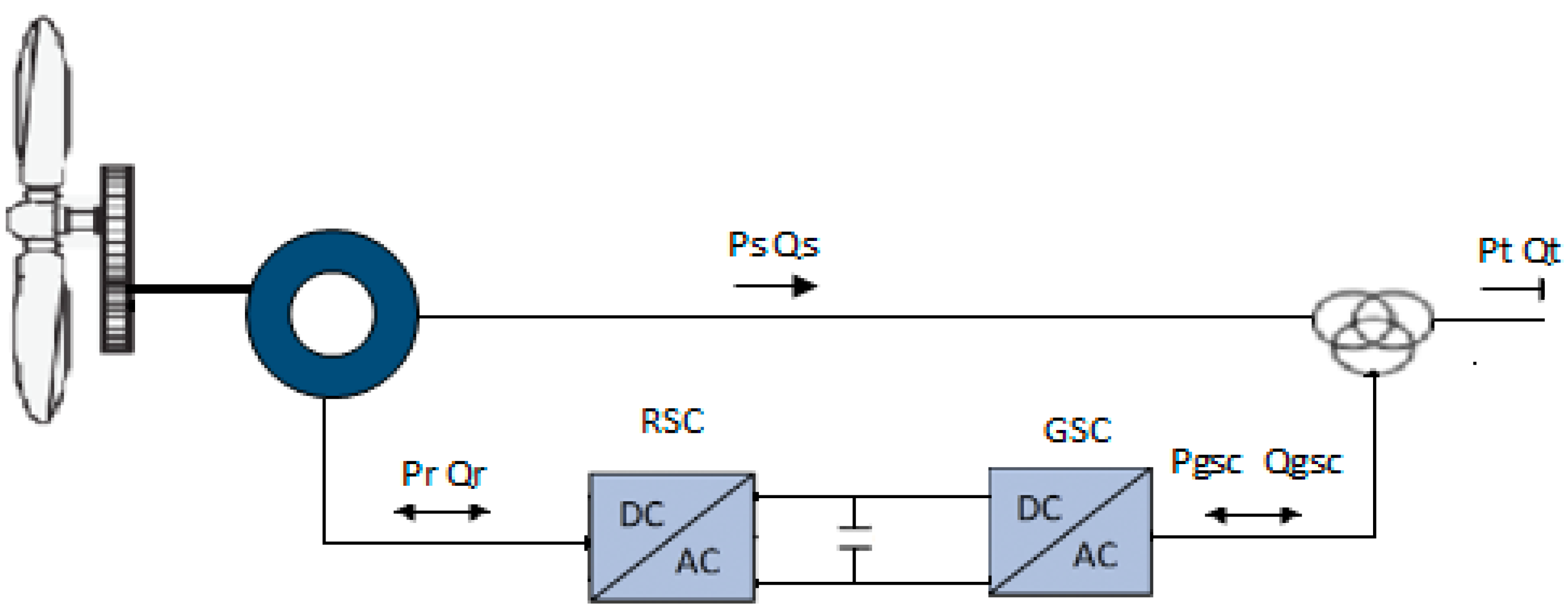
2. Power System Model Integrated with Wind Farm Using DFIG

A dynamic model of a DFIG wind turbine can be indicated in terms of the equations of a piece system. The stator winding is connected directly to the grid, while a bidirectional power converter feeds the rotor windings, allowing variable frequency operation in the rotor currents. This power converter is made up of two back-to-back insulated gate bipolar transistor (IGBT) bridges (rotor side converter, or RSC; and grid side converter, or GSC) linked by a DC bus. The wind turbine is also equipped with a blade pitch angle controller that limits wind power capture and rotational speed for high winds. Figure 1 represents its configuration.
The output power of the turbine is controlled to follow a determined power–speed characteristic, called tracking characteristic. The electrical output power on the network the wind turbine terminals are added to the power losses is compared to the reference power obtained from the tracking feature. In the converter system on the rotor side, AC voltage and Volt Ampere Reactive (VAR) are regulated. The DC–DC intermediate circuit contains two converters: first converter AC to DC and second converter DC to AC. The intermediate DC to DC circuit consists of current regulation, DC voltage and pitch control system. The last one is adjusted at zero degrees by the regulator of pitch angle to the extent that the speed is required to follow the characteristics of the control system. The DC voltage output from intermediate circuit was applied to the grid side converter which consists of an insulated gate bipolar transistor (IGBT) two-level inverter, generating an AC voltage at 60 Hz. A 12 MW wind farm consisting of eight 1.5 MW wind turbines connected to a 25 kV distribution system exports power to a 120 kV grid through a 30 km, 25 kV feeder. The wind speed is maintained constant at 15 m/s.

2.1. Mechanical System Model

The system mechanic contains the drive train and aerodynamic rotor. The model of the rotor expresses the mechanical torque extracted from the wind, defined by the actuator disk theory. This torque is transmitted to the DFIG rotor through the drive train, represented by the well known two masses model. In this model, two rotating masses—the aerodynamic rotor and the DFIG rotor—are elastically connected via springs, characterized by the stiffness and damping factor of the coupling [9].

2.2. Electrical System Model

The DFIG and its power converter are two important factors that can be indicated in the electrical system model. The DFIG system can be implemented under a fifth-order model to define its behavior. The four electrical equations are indicated in a direct (d)-quadrature (q) for the rotor and stator voltage coordinates, which include the synchronous turning speed in this wind farm. The equations are determined by
U d s = R s i d s + d d t φ d s ω φ q s
U q s = R s i q s + d d t φ q s ω φ d s
U d r = R r i d r + d d t φ d r ( ω ω r ) φ q r
U q r = R r i q r + d d t φ q r + ( ω ω r ) φ d r
where U represents the voltage, i represents the current, ω is the rotating speed, φ denotes the magnetic flux, R represents resistance and L inductance, indexes d and q stand for the direct and quadrature components, and indexes s and r refer to the stator and rotor, respectively.
Furthermore, the mechanical power available from a wind turbine is typically given by (5) [9]:
P w = 0.5 ρ π R 2 V w 3 C p ( λ , β )
C p = 1 2 ( λ 0.022 β 2 5.6 ) e 0.17 λ
λ = V w ω β
where Pw is the extracted power from the wind, ρ is the air density, R is the blade radius and ω β is the wind speed. C p is called the ‘power coefficient’ and is given as a nonlinear function of the parameters’ tip speed ratio λ and blade pitch angle β. The calculation of the performance coefficient requires the use of blade element theory. ω β is the rotational speed of the turbine. Usually, C p is approximated as [12]:
C p = α λ + β λ 2 + γ λ 3

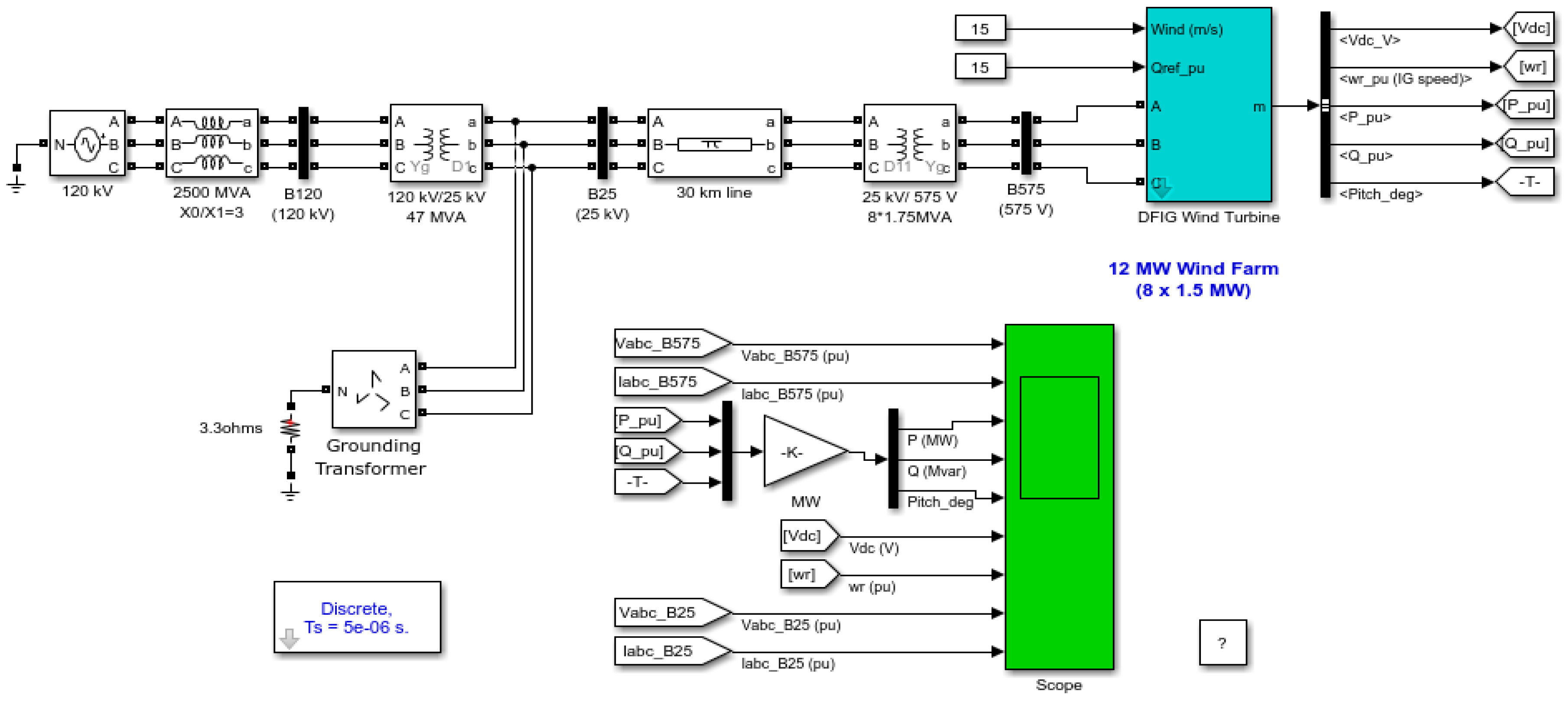
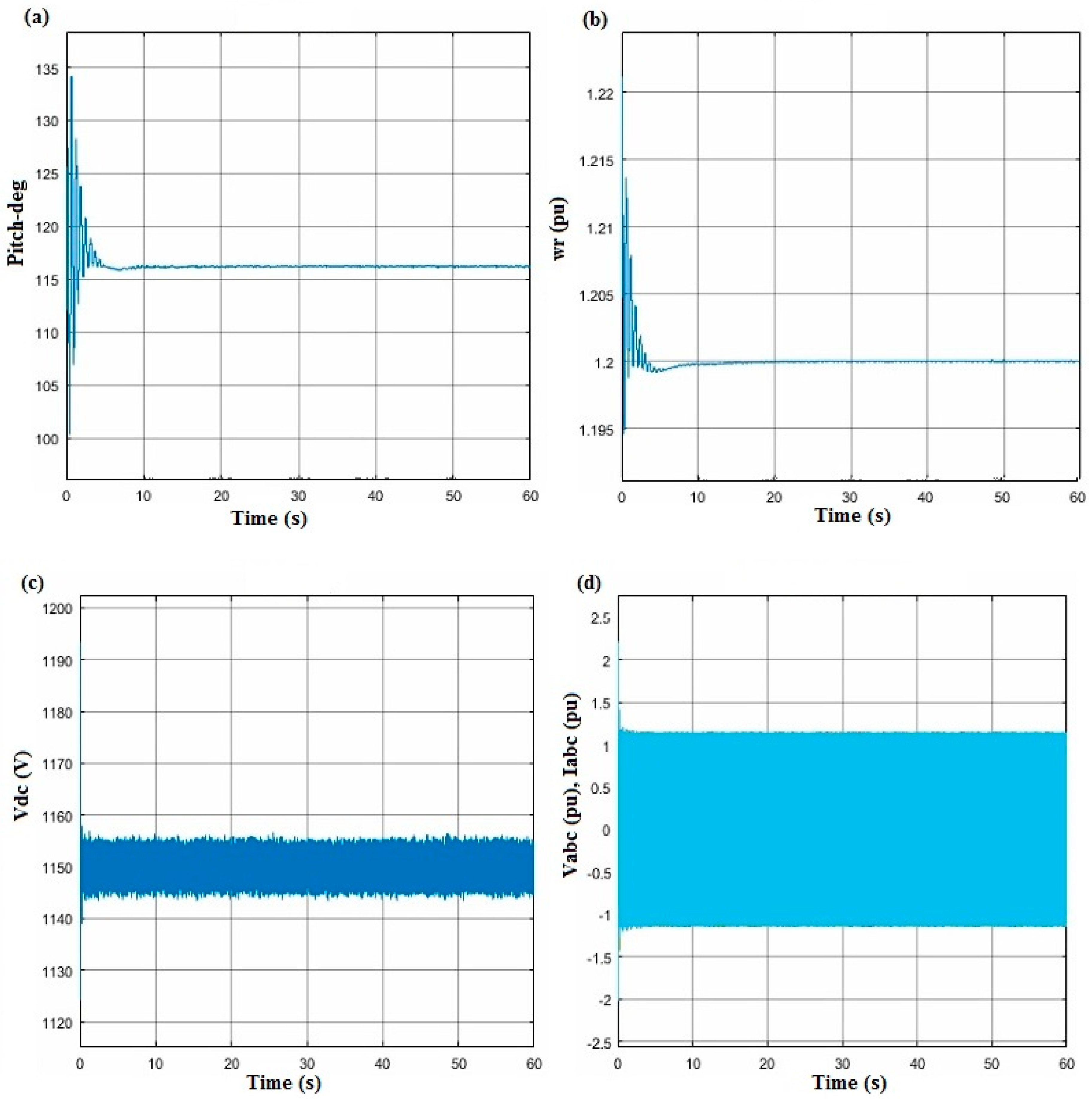
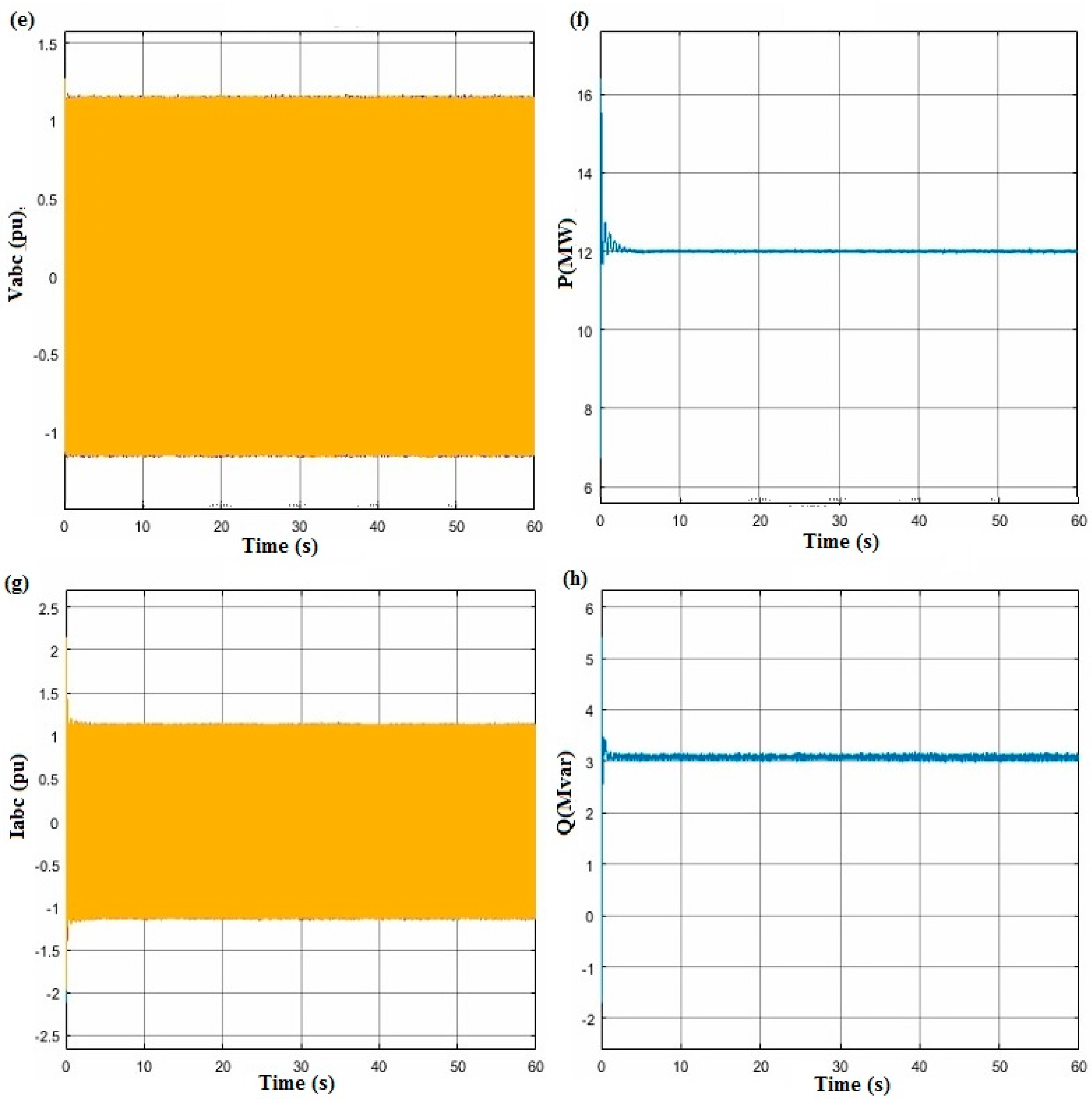
3. Simulation and Results

The Figure 2 define the model based on the doubly fed induction generator. This model consists of eight 1.5 MW wind turbines connected to a 25 kV distribution system which exports power to a 120 kV grid through a 30 km, 25 kV feeder. The eight 1.5 MW wind turbines form a wind farm of 12 MW of power.
In the following, we will represent and analyze simulation 1 over a period of 60 s by showing the graphs of the rotational speed, pitch angle, active power and DC link capacitor voltage and the current of wind turbines. Most of the variables of interest cited above were represented in pu values where the base power is the nominal power of each wind turbine (1.5 MW). The value 1 pu delimits the nominal power of the wind turbine. We will start by representing two important mechanical parameters, which are the rotational speed and the pitch angle of wind turbine. As we can see, the rotational speed of the rotor is regulated through the angle of the blades. From Figure 3a, the pitch angle starts to oscillate right after the disturbance. Nevertheless, it can be seen the oscillation decays after 5 seconds and the system is stable. Moreover, it is clear in Figure 3b that the rotational speed of the wind turbine starts at 1.2 pu during the first 10s of the simulation. However, the rotational speed decreases as well to a value below (1pu), which means the generator rotor of the wind turbine does not rotate at its rated value anymore. This behavior shows that the rotational speed is highly dependent on wind power. From Figure 3c, it can be seen that the DC link capacitor voltage shows small fluctuations on rotor active power and output power caused by wind speed variations. The voltage and currents considerably change the generator’s active and reactive powers, which are shown in Figure 3d. It also remarks in Figure 3e,g, that the wind farm DC voltage is the sum of the DC voltages of wind turbines, which means that the GSC is controlling the wind farm DC voltage by maintaining it to a set constant value and also assuring the active power exchange from the generator to the grid. It can also be seen from Figure 3f, h that the active power and reactive power diminution of the wind turbine fluctuates until the end of the simulation. The other parameter that is necessary to verify in order to check that our Simulink model is working perfectly is the DC voltage.

4. Conclusions

In this research, the DFIG and the dynamics operation were modeled to evaluate the responses and to assure the electrical distribution with the wind in terms of grid voltage and frequency fluctuations. Moreover, the main objective of this paper is the study on the dynamic behavior of the DFIG characteristic analysis and its effectiveness and optimal performance to assess the impact on the output variables of a wind farm contain many wind turbines. For this reason, the continuation of the proposal of this research is to make a hybrid system consisting of several wind turbines and an energy storage system will be selected to provide a clear idea and exact view of the distribution and degree of fluctuations as presented in the analysis and simulation in the pitch angle, current, and voltage curves to prevent such fluctuation situations and others. Each subsystem will be controlled via non-isolated power converters, and then coupled with grid or local load through the inverter. Simulations of the intelligent control system will also be improved through energy management among all the components of the hybrid system. Therefore, it is not enough to claim that one energy storage device is the best among all the others for each generator, but it is more appropriate to state that each of them has a better performance and is the most suitable for certain applications. Different configurations will be studied to eliminate the weaknesses of DFIG generator wind turbines that will allow the use of electronic power converters. The storage devices comprised in the hybrid system add the flexibility and capacity to the control and regulate the active power generation of the hybrid system, which yield to adapt the changes on the grid demand.

Conflicts of Interest

The authors declare no conflict of interest.

Abbreviations

The following abbreviations and notations are used in this manuscript:
DFIGDoubly fed induction generator
RESRenewable energy sources
PWMPulse width modulation
WECSWind energy conversion systems
ω β Rotational speed of turbine
V w Wind speed
Λ Tip speed ratio
β Blade pitch angle
UVoltage
RResistance
P w Power wind turbine
C P Polynomial   function   of   λ   and   β
GSCGrid source converter

References

  1. Pleßmann, G.; Erdmann, M.; Hlusiak, M.; Breyer, C. Global energy storage demand for a 100% renewable electricity supply. Energy Procedia 2014, 46, 22–31. [Google Scholar] [CrossRef]
  2. Bussar, C.; Moos, M.; Alvarez, R.; Wolf, P.; Thien, T.; Chen, H.; Cai, Z.; Leuthold, M.; Sauer, D.U.; Moser, A. Optimal allocation and capacity of energy storage systems in a future European power system with 100% renewable energy generation. Energy Procedia 2014, 46, 40–47. [Google Scholar] [CrossRef]
  3. IEC White Paper Energy Challenge:2010. Coping with the Energy Challenge The IEC’s Role from 2010 to 2030; IEC: Geneva, Switzerland, 2010. [Google Scholar]
  4. IRENA. Global Energy Transformation: A Roadmap to 2050, 2018th ed.; IRENA: Abu Dahbi, UAE, 2018. [Google Scholar]
  5. Sun, Z.; Wang, H.; Li, Y. Modelling and simulation of doubly-fed induction wind power system based on Matlab/Simulink. IET Conf. Publ. 2012, 2012. [Google Scholar] [CrossRef]
  6. Jami, H. World Wind Resource Assessment Report, 2014th ed.; World Wind Energy Association: Bonn, Germany, 2014. [Google Scholar]
  7. Rolán, A.; Pedra, J.; Córcoles, F. Detailed study of DFIG-based wind turbines to overcome the most severe grid faults. Int. J. Electr. Power Energy Syst. 2014, 62, 868–878. [Google Scholar] [CrossRef]
  8. Fernández, L.M.; García, C.A.; Saenz, J.R.; Jurado, F. Equivalent models of wind farms by using aggregated wind turbines and equivalent winds. Energy Convers. Manag. 2009, 50, 691–704. [Google Scholar] [CrossRef]
  9. Krim, Y.; Abbes, D.; Krim, S.; Mimouni, M.F. Intelligent droop control and power management of active generator for ancillary services under grid instability using fuzzy logic technology. Control Eng. Pract. 2018, 81, 215–230. [Google Scholar] [CrossRef]
  10. Precup, R.; Kamal, T.; Hassan, S.Z. Advanced Control and Optimization Paradigms for Wind Energy Systems; Springer: Singapore, 2019; ISBN 978-981-13-5994-1. [Google Scholar]
  11. Shi, G.; Zhang, J.; Cai, X.; Zhu, M. Decoupling control of series-connected DC wind turbines with energy storage system for offshore DC wind farm. In Proceedings of the 2016 IEEE 7th International Symposium on Power Electronics for Distributed Generation Systems (PEDG), Vancouver, BC, Canada, 27–30 June 2016. [Google Scholar] [CrossRef]
  12. Mu, W.; Wang, J.; Feng, W. Fault detection and fault-tolerant control of actuators and sensors in distributed parameter systems. J. Franklin Inst. 2017, 354, 3341–3363. [Google Scholar] [CrossRef]
  13. Li, W.; Chao, P.; Liang, X.; Sun, Y.; Qi, J.; Chang, X. Modeling of complete fault ride-through processes for DFIG-Based wind turbines. Renew. Energy 2018, 118, 1001–1014. [Google Scholar] [CrossRef]
  14. Nazir, M.S.; Wu, Q.H.; Li, M.; Luliang, Z. Lagrangian-Based Approach for Non-linear Dynamic Control of an Islanded Power System Short title: Non-linear dynamic control of power system. Int. J. Comput. Sci. Inf. Secur. 2017, 15, 24–29. [Google Scholar]
  15. Sarrias-Mena, R.; Fernández-Ramírez, L.M.; García-Vázquez, C.A.; Jurado, F. Improving grid integration of wind turbines by using secondary batteries. Renew. Sustain. Energy Rev. 2014, 34, 194–207. [Google Scholar] [CrossRef]
Figure 1. Doubly fed induction generator (DFIG) wind turbine scheme by Rotor side converter (RSC) and grid side converter (GSC).
Proceedings 63 00016 g001
Figure 2. Schematic of the doubly fed induction generator model of MATLAB/Simulink.
Proceedings 63 00016 g002
Figure 3. Schematization of the set output variables of DIFG: (a) pitch-deg; (b) Wr (pu); (c) Vdc (V); (d) Vabc (pu) Iabc (pu); (e) Vabc (pu) (f) Iabc (pu); (g) P (MW); and (h) Q (Mvar).
Proceedings 63 00016 g003aProceedings 63 00016 g003b
Publisher’s Note: MDPI stays neutral with regard to jurisdictional claims in published maps and institutional affiliations.

