Proceeding Paper

Optimal Sizing of RF Integrated Inductors for Power Transfer of Implantable Biosensors †

1
LSSDIA, ENSET Mohammedia, University of Hassan II Casablanca, Mohammedia 28830, Morocco
2
EEA & TI Laboratory, Faculty of Science and Technology, University of Hassan II Casablanca, Mohammedia 28830, Morocco
*
Author to whom correspondence should be addressed.
Presented at the 1st International Electronic Conference on Biosensors, 2–17 November 2020; Available online: https://iecb2020.sciforum.net/.
Proceedings 2020, 60(1), 30; https://doi.org/10.3390/IECB2020-07053
Published: 2 November 2020
(This article belongs to the Proceedings of The 1st International Electronic Conference on Biosensors)

Abstract

:
Energy recovery methods are currently receiving a very great deal of attention from the research community. Especially, in the case of implantable biosensors where wireless energy transfer has become the main technique in these applications. An implant is a medical device manufactured to replace a missing biological structure, support a damaged biological structure, or enhance an existing biological structure. Biosensors are man-made devices, in contrast to a transplant, which is a transplanted biomedical tissue. The method of energy transfer eliminates the risk of skin infection, as well as the need for invasive surgery to change the battery. In this paper, we present the efficient approach to design an optimized octagonal spiral inductor operating at a frequency of 2.4 GHz with an inductance L value of 4 nH and a maximum factor of quality Q. The principle part of this work is based on the use of a collection of methods called metaheuristics, which are approaches used to solve a wide range of optimization problems, in order to achieve a high-performance optimized design. The problem is represented by an objective function that will be implemented using a MATLAB script and then the validation of the results obtained will be performed using the advanced design system (ADS) microwave circuit simulation software.

1. Introduction

Nowadays, a lot of research is focused on the realization of integrated inductors to meet the needs and more operational for various applications: in signal processing to enter the realization of low-noise amplifiers [1], in biomedical engineering [2] including applications related to energy storage [3]. The design of such components requires specific techniques and mainly the use of three types of materials: a conductive material, a magnetic material, which in most cases is ferrite, iron-silicon alloys or nickel-silicon alloys in the case of inductance with a core and sometimes an insulator. The performance of the component depends on several factors, on the one hand on the magnetic properties of the material [4], if it is a low-frequency application we generally find magnetic conductive materials with high permeability.
In this paper the objective will be the design and optimization of an integrated inductor in complementary metal oxide semi-conductor (CMOS) technology for biosensors using the differential evolution algorithm (DE). The study consists of using the differential evolution algorithm to design a planar integrated inductor of the octagonal spiral type operating at a frequency around 2.4 GHz with a maximum quality factor and an inductance L which tends towards 4 nH, taking into account the different electrical and magnetic phenomena (the skin effect, the proximity effect…), which are reproduced in such structures.

2. Materials and Methods

2.1. Physical Model of Spiral Inductor

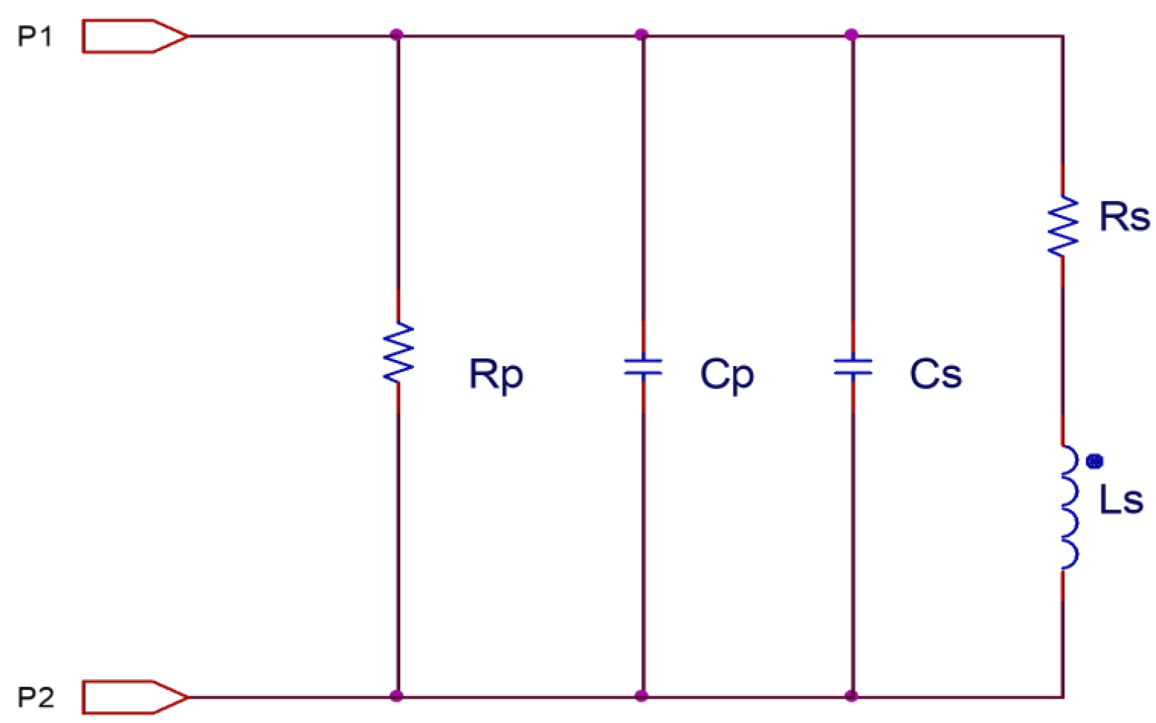
2.1.1. Equivalent Model

We have considered the equivalent circuit shown in Figure 1 to calculate the inductance value by the following equation:
L S = 1 2 π f I m ( 1 Y 12 )
The parameters of the physical model are calculated according to the geometrical parameters of the inductance by the following equations [5,6]:
  • Coupling capacity between the coils:
C s = n · w 2 · ε o x t o x M 1 M 2  
  • Parasitic capacitance:
C o x = 1 2 · l · w · ε o x t o x  
  • Capacity of substrates:
C s i = 1 2 · l · w ·   C s u b  
  • Resistance of the substrate:
R s i = 2 l · w · G s u b  

2.1.2. Inductance Ls

Several methods are presented in the literature to calculate the Ls such as wheeler’s method [7], Baryan’s method [8], Terman’s method, monomial method and others. In our simulation we will use the monomial method because it remains valid for a small number of turns. The monomial expression used to calculate the self-inductance is given by the following relation:
L s = β · D o u t α 1 · W α 2 · D a v g α 3 ·   N α 4 ·   S α 5
N is the number of turns, β, α1, α2, α3, α4 and α5 are coefficients according to the geometrical shape of the inductance studied, Davg is calculated from inner diameter Din of the inductance outer diameter Dout by the following relation:
D a v g = ( D i n + D o u t ) 2 D o u t = D i n + 2 · N · W + 2 · ( N 1 ) · S
The coefficients β, α1, α2, α3, α4 and α5 are given as follows in the Table 1:
1.33   ×   10 3

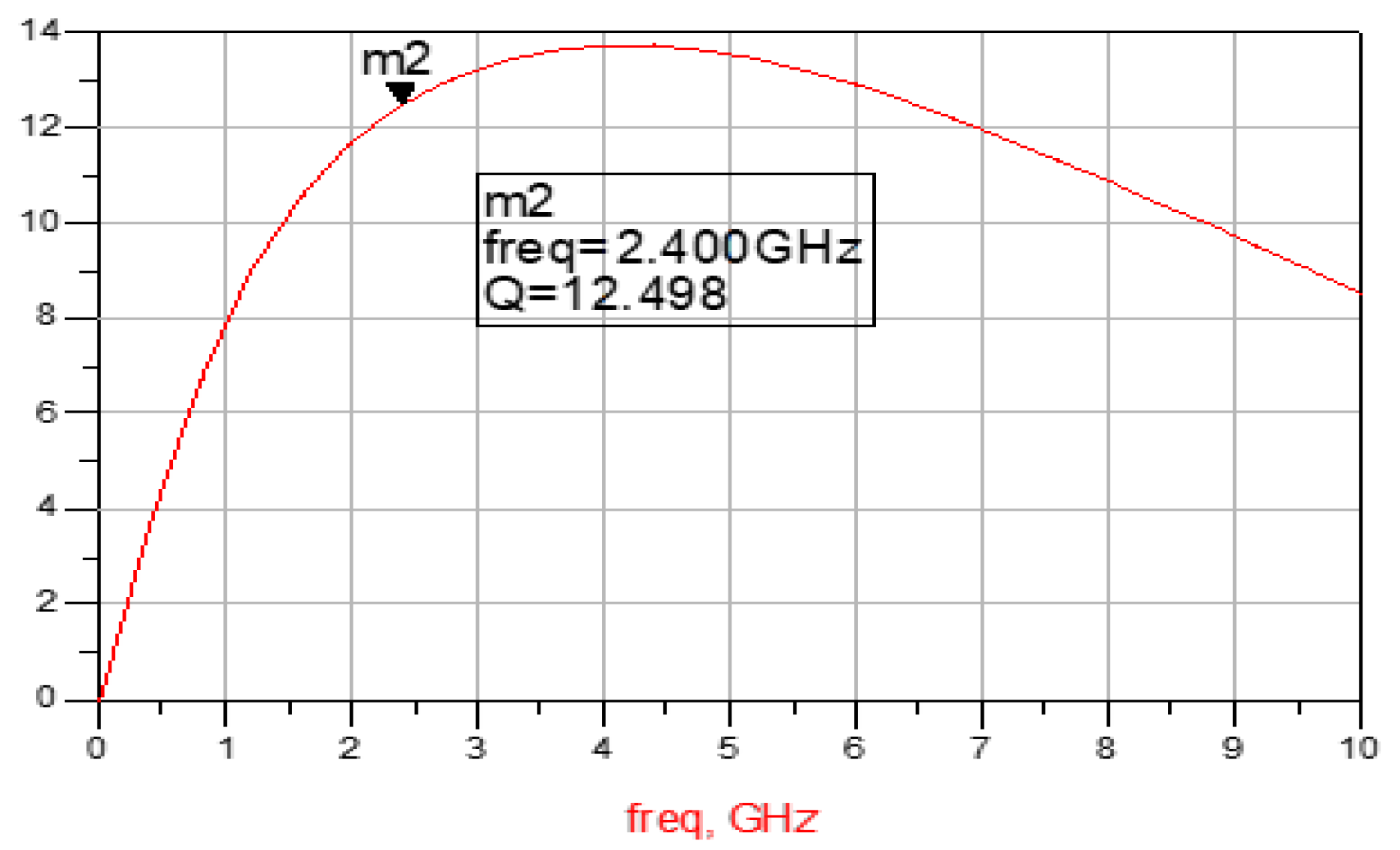
2.1.3. Factor of Quality-Q

To calculate the quality factor Q, a parallel equivalent schema of the spiral inductance is proposed, this scheme is characterized by the parallel capacitance Cp and parallel resistance Rp. The Figure 2 below shows the proposed parallel model.
The quality factor is defined in the following equation as follows:
Q = ω L S R S · R P R P + [ ( ω L S R S ) 2 + 1 ] R S · [ 1 ( C P + C S ) R S 2 L S ω 2 L S ( C P + C S ) ]  

2.2. Differential Evolutionary Algorithm (DE)
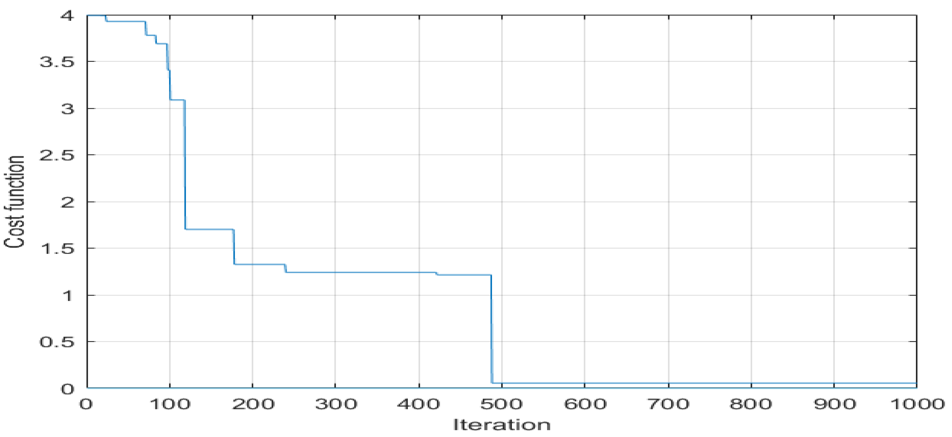
Differential evolutions, or DE, has been proposed by Storn and Kenneth Price [9]. It is an algorithm inspired by genetics and evolutionary strategy, it is also based on the three operations: mutation, crossover and selection. The mutation generates new elements from certain elements randomly chooses then the crossing between the parents and the created elements and a selection operation to have only the most suitable elements in the generation.

Objective Function

We are looking to maximize the quality factor Q expressed in equation x. This equation will be considered as an objective function (OF), this amount to:
  • Maximize the quality factor Q which depends on the geometrical parameters of the inductor (N, W, S);
  • We will introduce the cost function Qreq = 1/Q, it represents the desired quality factor, so the problem is transformed towards a minimization of Qreq, in order to maximize the quality factor Q;
  • All this will be done by the following constraints that must be satisfied:
2 ≤ N ≤ 10
20 ≤ W ≤ 100
3 ≤ S ≤ 50

3. Results

At 1000 iterations, after satisfying the stopping condition the algorithm provides the best combination of geometrical parameters corresponding to the optimal quality factor Q, the Figure 3 shows the result of the inductance optimization by the DE method. Figure 4 shows the momentum-ADS simulation results Q using the obtained optimal values by the DE-based method
The Table 2 shows the optimal parameters given by the DE algorithm:

4. Discussion

The simulation has shown very clearly that an octagonal inductance can be designed with the desired criteria with a very high percentage, in fact we have obtained a fairly high-quality factor, and the simulation value is close to the value provided by the DE algorithm, with an error that does not exceed 8%.

References

  1. Jeamsaksiri, W.; Mercha, A.; Ramos, J.; Linten, D.; Thijs, S.; Jenei, S.; Detcheverry, C.; Wambacq, P.; Velghe, R.; Decoutere, S. Integration of a 90 nm RF CMOS technology (200 GHz fmax—150 GHz fT NMOS) demonstrated on a 5 GHz LNA. In Proceedings of the 2004 Symposium on VLSI Technology, Honolulu, HI, USA, 15–17 June 2004; pp. 100–101. [Google Scholar]
  2. Chen, L.Y.; Benjamin, C.K.T.; Alex, L.C.; Gregor, S.; Victor, T.; Darren, J.L.; Philip, H.S.W.; Michael, V.M.; Bao, Z. Continuous wireless pressure monitoring and mapping with ultra-small passive sensors for health monitoring and critical care. Nat. Commun. 2014, 5, 1–10. [Google Scholar] [CrossRef] [PubMed]
  3. Eom, K.; Jeong, J.; Lee, T.H.; Lee, S.E.; Jun, S.B.; Kim, S.J. Columnar transmitter based wireless power delivery system for implantable device in freely moving animals. In Proceedings of the Engineering in Medicine and Biology Society (EMBC), 2013 35th Annual International Conference of the IEEE, Osaka, Japan, 3–7 July 2013; pp. 1859–1862. [Google Scholar]
  4. Yue, C.P.; Ryu, C.; Lau, J.; Lee, T.H.; Wong, S.S. A Physical model for planar spiral inductors on silicon. In Proceedings of the IEEE International Electron Devices Meeting (IEDM) Technical Digest, San Francisco, CA, USA, 8–11 December 1996; pp. 155–158. [Google Scholar]
  5. Bouyghf, H.; Benhala, B.; Raihani, A. Analysis of the impact of metal thickness and geometric parameters on the quality factor-Q in integrated spiral inductors by means of artificial bee colony technique. Int. J. Electr. Comput. Eng. (IJECE) 2019, 9, 2918–2931. [Google Scholar] [CrossRef]
  6. Bouyghf, H.; Benhala, B.; Raihani, A. Artificial bee colony technique for a study of the influence of impact of metal thickness on the factor of quality-Q in integrated square spiral inductors. In Proceedings of the 4th International Conference on Optimization and Applications (ICOA 18), Mohammedia, Morocco, 26–27 April 2018. [Google Scholar]
  7. Mohan, S.S.; Hershenson, M.D.; Boyd, S.P.; Lee, T.H. Simple accurate expressions for planar spiral inductances. IEEE J. Solid State Circuits 1999, 34, 1419–1424. [Google Scholar] [CrossRef]
  8. Bryan, H.E. Printed inductors and capacitors. Tele-Tech. Electron. Ind. 1955, 14, 68. [Google Scholar]
  9. Storn, R.; Price, K. Differential evolution—A simple and efficient heuristic for global optimization over continuous spaces. J. Glob. Optim. 1997, 11, 341–359. [Google Scholar] [CrossRef]
Figure 1. (a) Physical model of octagonal inductor; (b) simplified equivalent circuit.
Proceedings 60 00030 g001
Figure 2. Parallel model of spiral inductance.
Proceedings 60 00030 g002
Figure 3. Cost function of the spiral inductor versus Iterations.
Proceedings 60 00030 g003
Figure 4. Simulation of quality factor Q.
Proceedings 60 00030 g004
Table 1. Table of coefficients used in the monomial expression.
Geometryβα1α2α3α4α5
Octagonal 1.33   ×   10 3 −1.21−0.1632.431.75−0.049
Table 2. Parameters given by the DE algorithm.
S (µm)w (µm)NDout (µm)Lsreq (nH)LDE (nH)QDE
4.5613.623.2122343.9513.46
Publisher’s Note: MDPI stays neutral with regard to jurisdictional claims in published maps and institutional affiliations.

