Proceeding Paper

Battery Electric Drive of Excavator Designed with Support of Computer Modeling and Simulation †

1
Institute of Mechanical Design, Faculty of Mechanical Engineering, Brno University of Technology, 60190 Brno, Czech Republic
2
Bosch Rexroth, 60190 Brno, Czech Republic
3
Institute of Automation and Computer Science, Faculty of Mechanical Engineering, Brno University of Technology, 60190 Brno, Czech Republic
4
Faculty of Electrical Engineering and Communication, Brno University of Technology, 60190 Brno, Czech Republic
*
Author to whom correspondence should be addressed.
Presented at the First World Energies Forum, 14 September–05 October 2020; Available online: https://wef.sciforum.net/.
Proceedings 2020, 58(1), 25; https://doi.org/10.3390/WEF-06927
Published: 12 September 2020
(This article belongs to the Proceedings of The First World Energies Forum—Current and Future Energy Issues)

Abstract

:
The motivation for this article was to describe the creation of a battery electric drive of a smaller excavator of a well-known manufacturer. The aim of the excavator electrification research was to replace its internal combustion engine with an electric motor. The innovated excavator does not burden its surroundings with gas exhalations and excessive sound emissions, so that it can work in confined spaces or protected areas. Simulation models of electric and hydraulic parts of the drive were created to select the most suitable solutions verified or predicted by simulations in a Matlab/Simulink environment. Tests have shown that the excavator is capable of operating for at least 7 h without recharging the battery. The other main achieved results of the project are a functional model of zero emissions of mini-excavator exhalation gases with significantly reduced noise, a proven control algorithm in the form of software, and its utility model according to the patent application 2018-35127 adopted by the Industrial Property Office of the Czech Republic. Innovation of the solution of the excavator was awarded the Gold Medal at the Brno International Engineering Fair in 2018.

1. Introduction

The worldwide trend in the construction of building, earthmoving, forest, and similar machines is not only to reduce their fuel consumption, but also to reduce the load of gaseous and acoustic emissions that burden their surroundings. There are numerous solutions by researchers and designers. One of the major pathways is the electrification of the drive using an electric battery (electric accumulator). Mathematical modeling and computer simulation play an important role in this research, enabling the search for optimal solutions in virtual space. The aim of our research was to create an electric battery drive of a small excavator up to two tons by replacing the diesel engine with an electric motor together with the creation of a new system of internal control of the excavator subsystems. The new design was made in our own way after completing a patent search to avoid a patent conflict.
Within the framework of a grant project, Bosch Rexroth [1], in cooperation with Brno University of Technology, developed the drive and control of a gas emission-free excavator after previous cooperation involving the kinetic energy recovery of heavy vehicles with frequent starting and braking.
As the excavators are often used in the building industry, considerable attention has been paid to their construction and improvement in respect to electrification worldwide. The advantage of the described excavator is the drive without gas exhalations.
Recently, new electrified excavators of various innovative designs and properties can be found on the world market. Caterpillar [2], along with Pon Equipment, produced an all-electric 26 ton excavator with a 300 kWh battery pack in an effort to electrify the construction equipment. They built a prototype in Gjelleråsen, Norway, for the construction company Veidekke.
Komatsu Ltd. [3] developed an electric battery-driven excavator. When fully charged, this battery enables from two to six hours of operation. The machine allows for real-time monitoring of power consumption and charging conditions on the built-in monitor panel. It also allows for the remote monitoring of that information together with the machine location and operating conditions via the KOMTRAX system.
The Liebherr [4] electric excavator R 9200 E with a rated output of 850 kW is the biggest excavator on Eurovia mine’s 350 sites—up to 25% less maintenance cost compared to a diesel excavator.
Takeuchi [5] developed an e240 4 t class battery-powered excavator in 2017. The e240 is a battery version of the company’s TB240 diesel model. The machine operates for nine hours at 65% of full load. It charges from a standard 220 V power outlet and take around 10 hours to go to full charge from zero.
Wacker Neuson [6] debuted its first fully electric, battery-powered EZ17e compact excavator in 2018. All hydraulic functions are as powerful as those of the conventional model. The battery is integrated into the existing engine compartment. The EZ17e weighs almost exactly the same as the diesel version and can be transported on a trailer.
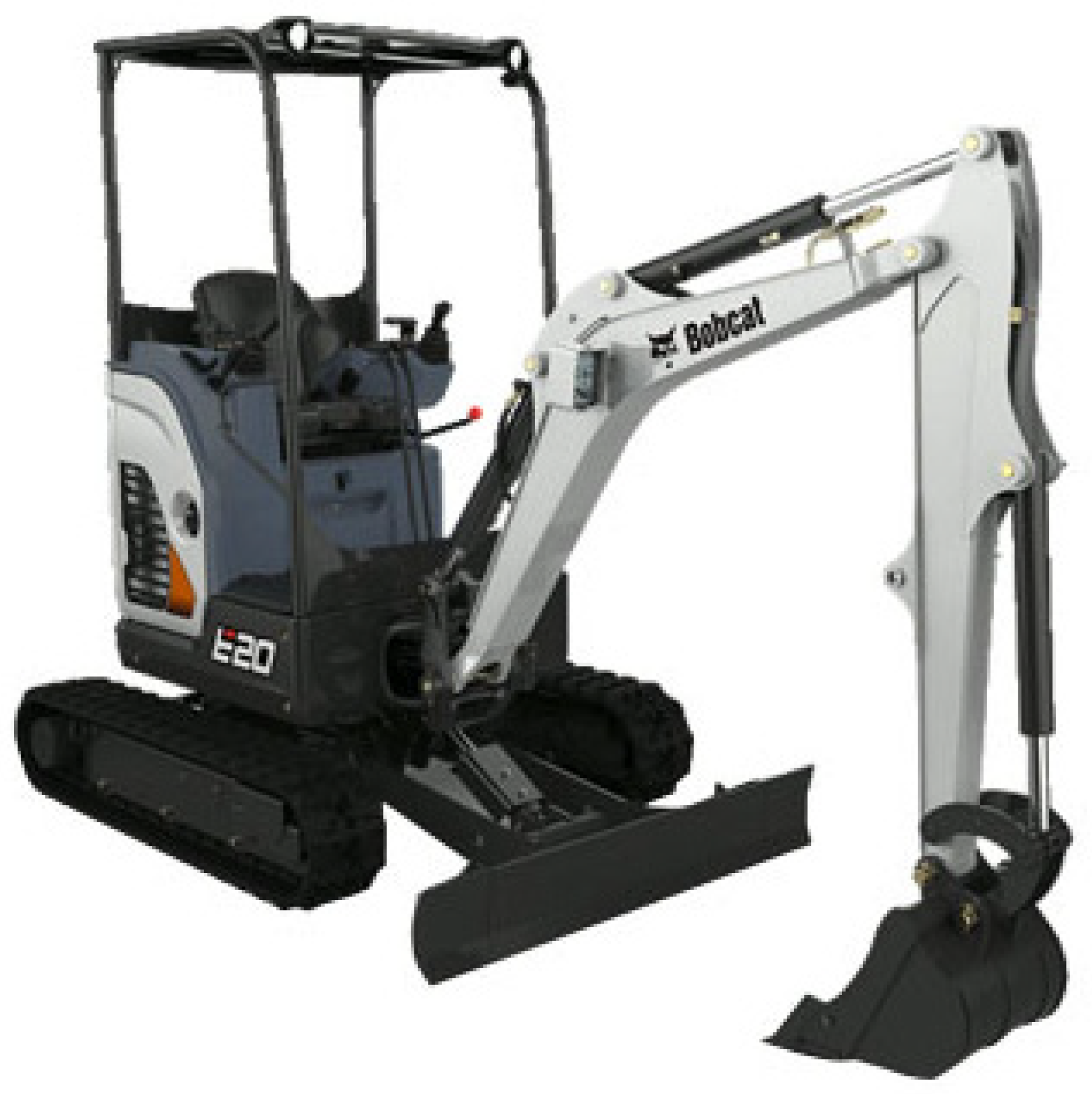
Bobcat [7] rolled out the E10e, its first electric mini excavator. The machine—fully electric, one-ton mini excavator—was built alongside its diesel-powered siblings, the E08 and E10z mini excavators. Kobelco [8] introduced its excavator - the addition to the Generation 10 series.
A lot of different solutions are proposed in the literature to improve machinery fuel efficiency, and many of these are based on hybrid solutions. The aim of Casoli [9] was to present a hybridization methodology that allows for the comparison of different system layouts, to determine the dimensions of the energy storage devices, and finally to determine the most effective hybrid system layout.
Electrification of excavators was described in Vauhkonen [
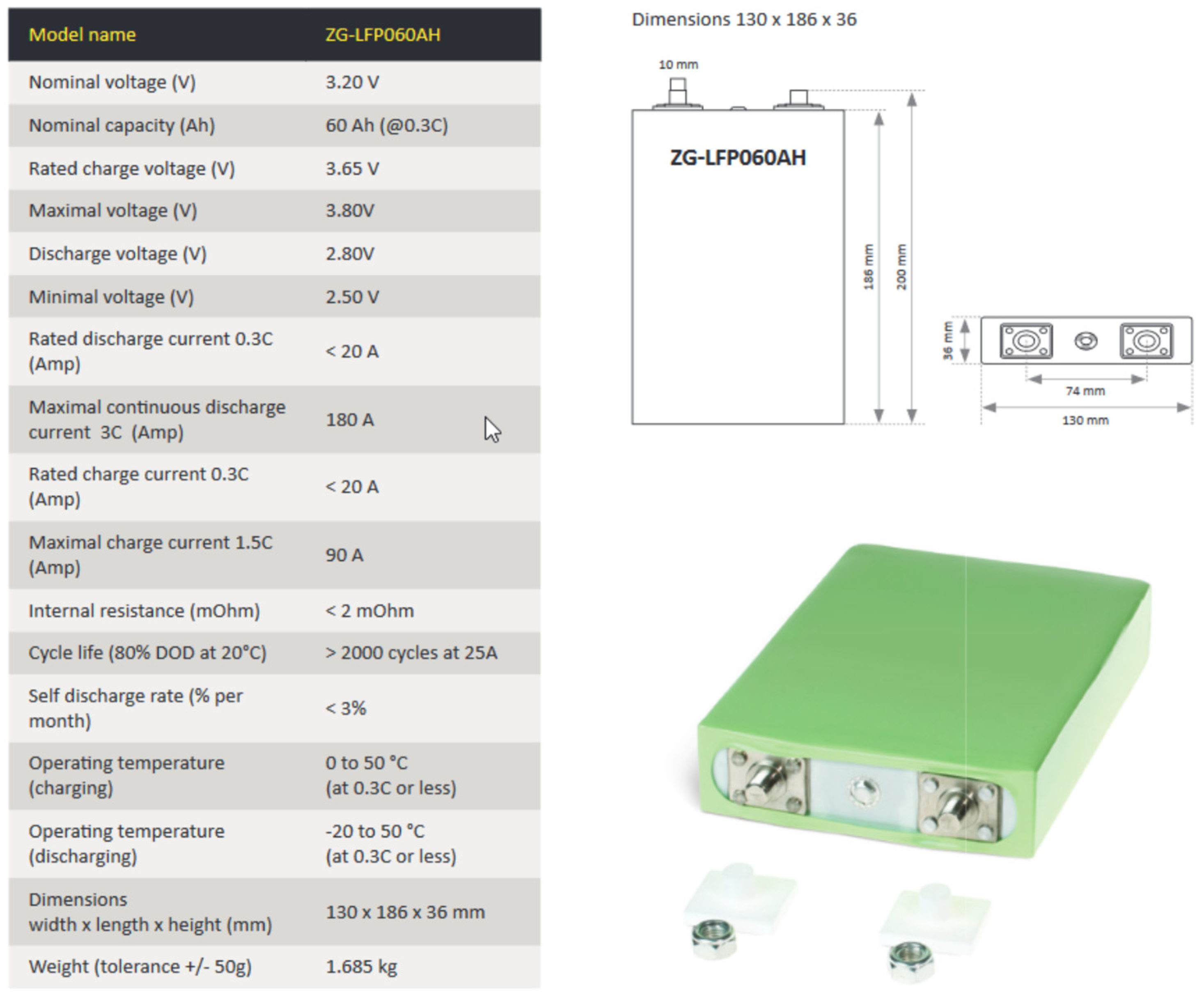
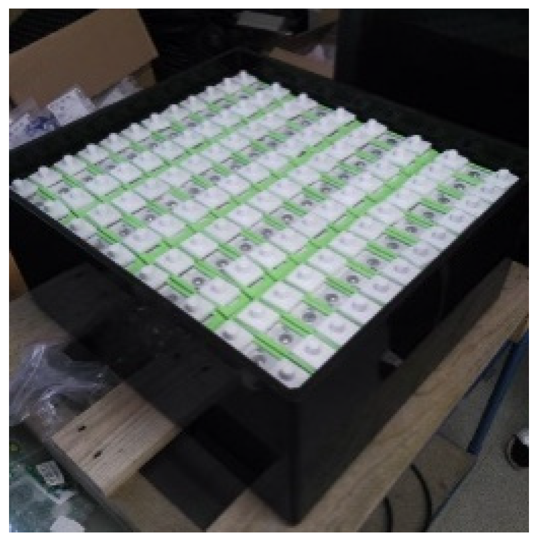
10]. For this study, a JCB Micro excavator was chosen as a building platform. The 14 kW diesel-powered engine with its required equipment was replaced with a 10 kW electric motor. Four lithium titanate batteries, with a total voltage level of 96 V and a capacity of 60 Ah, powered the electric motor.
With the electric drive, while maintaining the same performance, the operating time was substantially reduced compared to the diesel-powered drive.
Xu [11] studied modeling of mechanical and hydraulic subsystems for the simulation, design, and control development of excavator systems. As a result, various approaches in the hydraulic system modeling were presented. A recent trend in the development of off-highway construction equipment, such as excavators, is to use a system model for model-based system design in a virtual environment.
Modeling of hydraulic systems dynamics by means of differential and algebraic equations can be found in Nevrly [12] and Nepraz [13]. Casoli [14] presented the results of a numerical and experimental analysis conducted on a hydraulic hybrid medium-size excavator. Its standard version was modified using the energy recovery system; its layout was designed to recover the potential energy of the boom, using a hydraulic accumulator as a storage device. The recovered energy was utilized through the pilot pump of the machinery, which operates as a motor, thus reducing the torque required from the internal combustion engine. An experimental fuel saving of about 4% was noted over a testing working cycle.
The objective of the thesis of Alvin [15] was to develop a fast simulation model to replicate the functioning of the excavator system. The paper by Nevrly et al. [16] introduced a simulation of drive for electric-hydraulic excavators, basic model schemes of the drive system, simulation models of the electric motor system, and the pump system driven by the electric motor. Examples of simulation results—time courses of model quantities—were received either by means of Matlab/Simulink or a set of differential equations.
An energy recovery system integrating flywheel and flow regeneration for a hydraulic excavator boom system is described in Li [17]. Implementing the energy recovery system is a solution to improve energy efficiency for hydraulic excavators. A flywheel energy recovery system is proposed based on this concept. A hydraulic pump motor is employed as the energy conversion component and a flywheel is used as the energy storage component. The implementation of flow regeneration has two benefits: downsizing the displacement of the “hydraulic pump motor” and extra improvement of energy efficiency. A potential energy recovery and regeneration system for hybrid hydraulic excavators based on a multi-cylinder structure working device as a new invention is presented in Zhang [18].
Energy balancing for zero emission excavators was described in Jurik [19]. The author shows that efficient balancing of energy flows cannot be solved only by optimizing one subsystem, but rather that only the consistency of these subsystems enables the efficient balancing of energy flows for the efficient use of limited power sources—battery packs.
Improving energy efficiency of an electric mini excavator using a special start-and-stop logic system is described in Hassi [20]. The benefits of this system were measured using a test cycle with the old and new configurations. According to the authors, improvement in the operating time proved to be at least 50% longer than that of the old configuration. The efficiency study of an electric-hydraulic excavator was presented in Salomaa [21]. A Matlab model was utilized to study the total energy consumption and power distribution of the micro-excavator. The model consists of the hydraulic and mechanical systems related to the actuation of the front hoe, i.e., boom.
In Liu [22], achievement of fuel savings in a wheel loader by applying hydrodynamic mechanical power split transmissions was described. In this paper, the torque converter was replaced with a hydrodynamic mechanical power split transmission for improving the fuel economy of wheel loader. Based on the probability similarity theory, the typical operating mode for the vehicles was constructed and used to evaluate the energy consumption performance of the selected solutions.
As part of the development of the electric excavator, we prepared a patent study to avoid a patent collision with previously patented solutions. These included, in particular, patents from Kubota, Takeuchi, Hitachi, and Terex (Demag).

2. Overall Characteristic of Solution

Based on the patent search, the possibilities of solving the electric drive of the excavator were analyzed, then the structure of the functions was determined, and the elements of the excavator system were selected. A risk analysis was performed and the E19 excavator manufactured by Bobcat was chosen as a suitable starting machine for this task (Figure 1).
To solve the electrification of the excavator, it was expedient to divide the whole excavator into partial parts, e.g., according to Figure 2. The diagram shows the functions that is subsequently manifested in mathematical modeling. To monitor and analyze the internal and external context of the physical quantities involved, a design of a virtual solution, the concept of the structure of subsystems—including the control system—was performed. Mathematical models of subsystems in the Matlab/Simulink environment of MathWorks were compiled using the industry-oriented toolboxes Simscape, SimHydraulics, and SimMechanics. Subsequently, variant solutions were developed and verified by simulations and measurement. Testing of machine functions was performed by a system of targeted measurements of excavator parameters with subsequent data processing and verification of mathematical models.
The drive of the excavator was designed, including the battery power supply system and the combination of the motor and the frequency converter. The connection of the electric motor, controller, and electric battery is evident from the model of the drive subsystem in Figure 3.

3. Electrical Part of the Solution

3.1. The Electric Motor

The electric motor is a synchronous three-phase motor with permanent magnets powered by electric accumulator. It drives the pump via a belt drive. It was developed for application in an emission-free excavator.
Engine type: PMSM-prototype Maximum speed: 6000 rpm
Supply voltage: 48 VCurrent: approx. 200 A (continuous), max. approx. 400 A
Number of poles: 6 Torque: 40 Nm (permanent), 80 Nm (short-term)
Weight: 17 kg Maximum power: 20 kW

3.2. Electric Battery 48 V, Li-Fe Cells

The battery consists of pack of connected electric cells (Figure 4 and Figure 5). This battery is the only source of energy for driving the excavator’s electric motor. The battery includes a BMS (Battery Management System) module, which monitors the status of the cells. The battery was developed based on specifications from Bosch Rexroth.
Battery pack capacity: 15 kWh
Battery pack voltage: 48 VCell voltage 3.65 V
Weight: up to 90 kgDimensions: 550 × 490 × 360 (height) mm
An important factor is the charging time to reach full capacity while complying with all safety rules, such as the temperature of individual cells. This is approximately 5 h; the power supply has an output of 1.5 kW at a voltage of 240 V. One of the ways to improve charging is to use three-phase charging of the battery (Figure 6).
Electrical parts were laboratory measured, inspected, and, if necessary, modeled and computer simulated (Figure 7). Special care was given to the electric battery and a specially made electric motor.

4. Excavator Hydraulics

In terms of force, the hydraulic system is of fundamental importance for the operation of the excavator. The simplified diagram of a standard hydraulic excavator can be seen in Figure 8, which shows the functional links between the basic elements of the system—the pump for the drive, main valve, hydraulic rotary motors, and hydraulic cylinders.
A more detailed hydraulic diagram of a substantial part of the hydraulic system of excavator E19 is shown in Figure 9, where the details of the connection of hydraulic cylinders, directional valves, auxiliary valves, etc. can be seen.

5. Mathematical Models, Simulation

5.1. Modeling of Processes in the Excavator

The aim was to create models of excavator systems and their subsequent use for the purposes of simulation prediction, function verification, and optimization. For reasons of clarity, greater versatility of use, and easier work with models, a modular and multilevel model concept was chosen. The models developed in the Matlab/Simulink environment are sufficiently universal and enable simulations of various excavator processes. Separately applicable bucket, arm, boom, and boom turn subsystems are available to facilitate simulations of the excavator’s main movements. As an example of a hydraulic subsystem, Figure 10 shows the model of the pump and its connection to the hydraulic system. The control signals are optionally generated by the Signal Builder block and control the speed and the ideal source of torque. This source controls the variable displacement and pressure compensated pump, while all significant mechanical and hydraulic quantities are automatically registered, as shown in the diagram.
Another example is the model of the four-way directional flow valve (Figure 11). Such a valve distributes the oil flow according to the control electric signal.
When modeling hydraulic directional valves, the goal was to find the parameters of the models so that the behavior of the models corresponded as closely as possible to the characteristics of the directional valves listed in their catalog sheets. The models and their parameters were made more accurate during the work after tests on a functional sample of the excavator. The proposed directional valve models include physically existing nonlinearities (insensitivity, saturation transition).

5.2. 3D Modeling of Aggregate Placement

3D models of the drive elements were created and variant designs of their installation into the excavator structure were made, after which a variant of the installation solution according to Figure 12 was selected.

6. Control of Subsystems and Excavator System

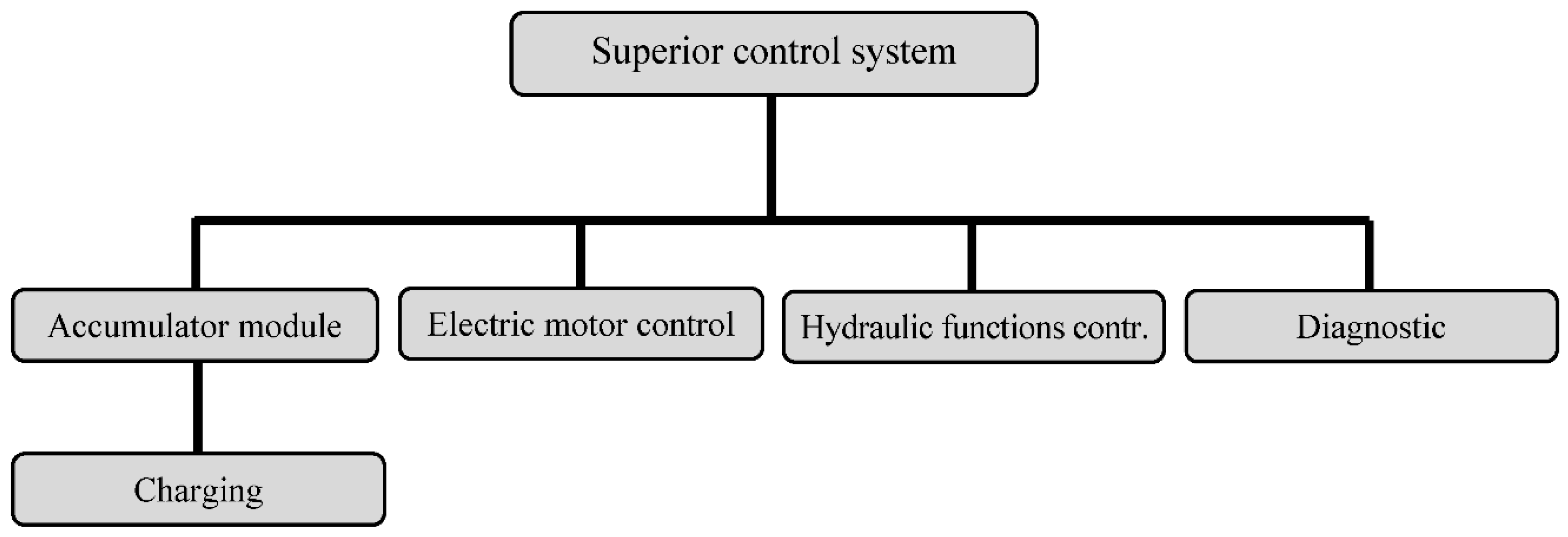
Following the results of the patent search, a specific control algorithm was created; this is the basic distinguishing element of the solution in comparison with other currently known solutions for controlling the excavator drive. The algorithm was created on the modular basis of the Bodas system. The hierarchy of the main parts of the control system is shown in Figure 13. The superior control system controls the battery module (with the connected charging block), electric motor control, hydraulic functions control, and diagnostics.
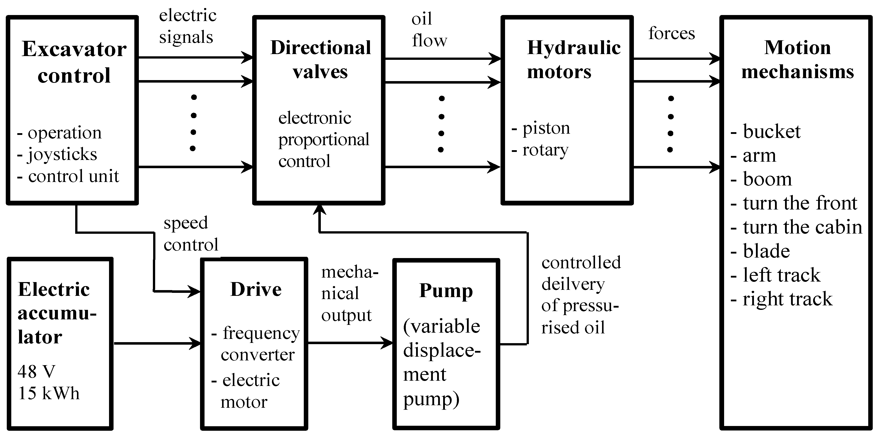
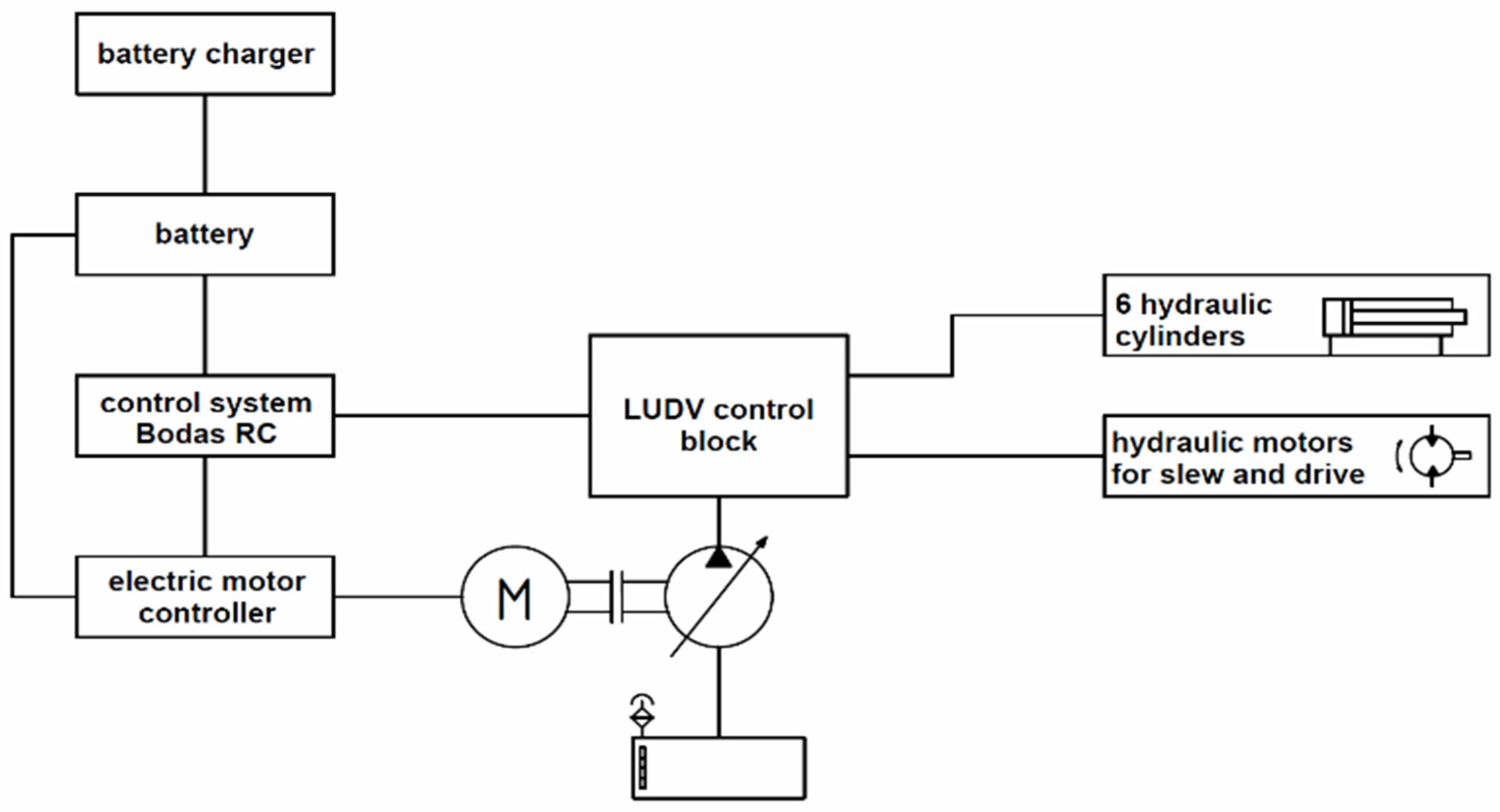
A more detailed scheme of the excavator control is shown in 
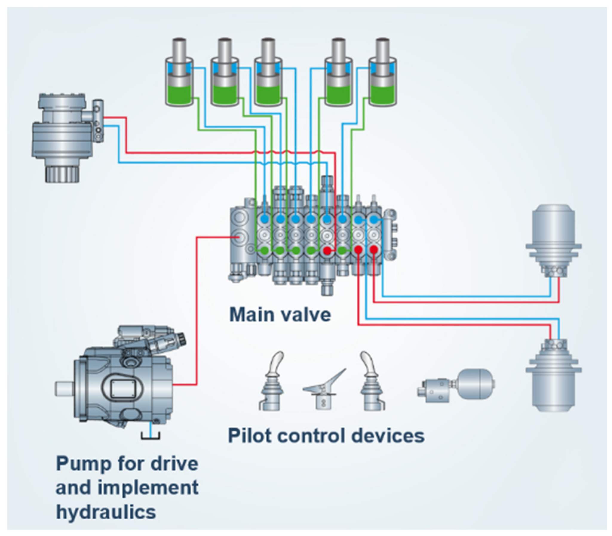
Figure 14. The initiating electrical signals come from the manual control block of the excavator operation to the hydraulic directional valve block and to the drive block (frequency converter, electric motor). The electric current from the electric accumulator leads to this block and then goes on to the pump block and farther to the hydraulic directional valves. The pressure oil flows from the hydraulic distributors to the hydraulic motors, which move the working mechanisms of the excavator.
From the point of view of control, the decisive block is “operation control,” which implements the interaction between the operator and the excavator. It contains a microcomputer control unit that generates control electric currents for controlling oil flows in directional valves. Control is of an “offline” type, i.e., without feedback from the actual controlled movements.
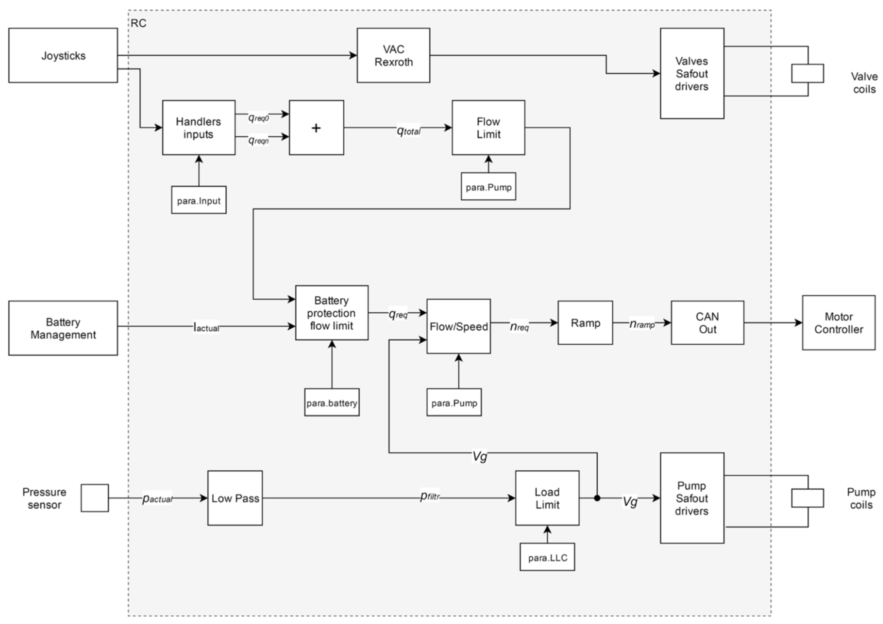
The data flow structure of the basic software modules for controlling the switchboards, the electric motor controller, and the pump can be seen in Figure 15. The inputs are signals from the manual control, from the battery management, and from the pressure sensor. These signals enter a set of sub-blocks, such as a low limiter, current protection of the accumulator, ramp block, etc. The output signals go to the coils of the electromagnets of the hydraulic routers, the motor controller, and the pump coils.
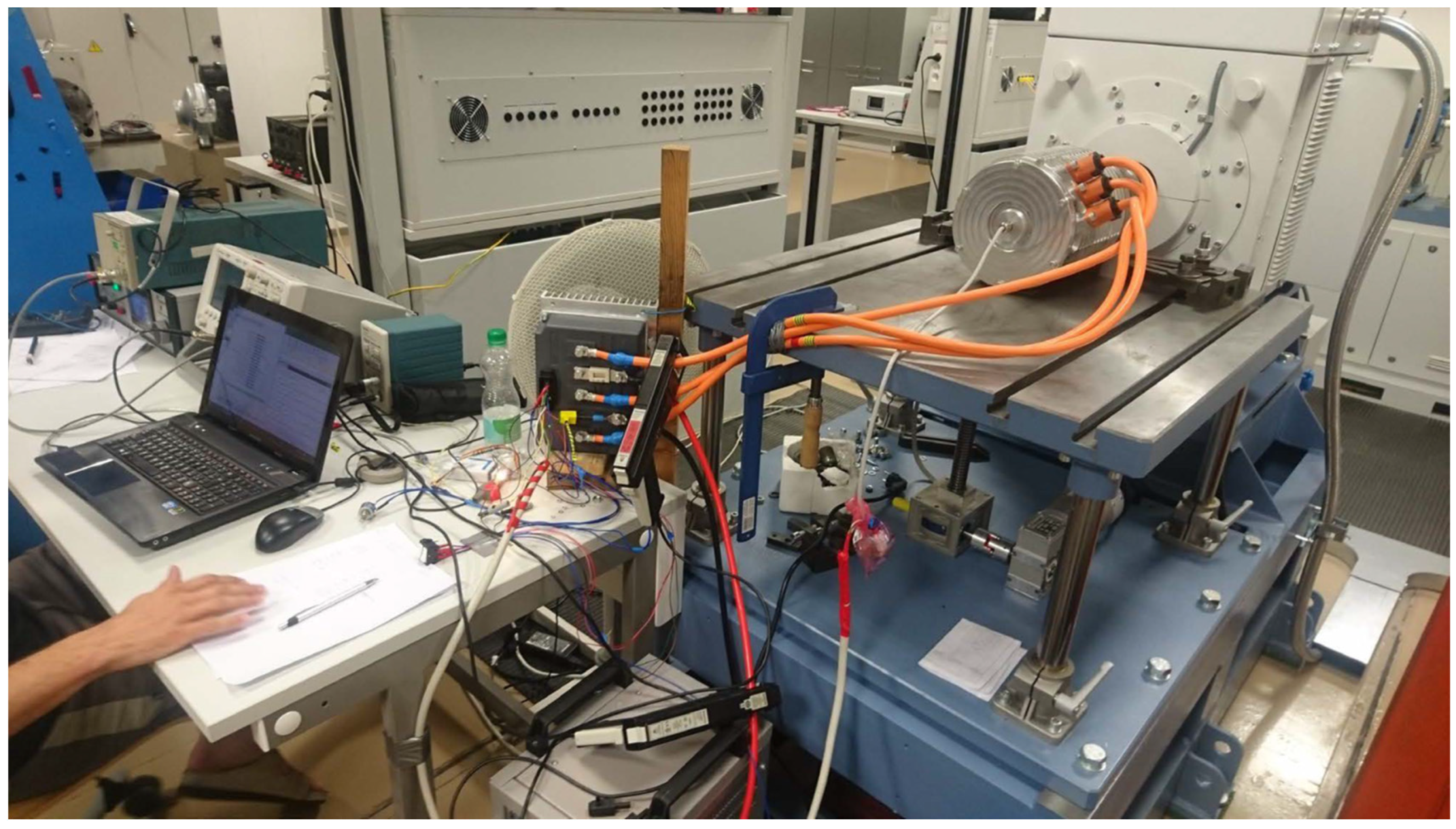
7. Experiments

The research used a methodology of theoretical and experimental verification of drive parameters, including the measurement of electrical, mechanical, hydraulic, and functional safety parameters of the excavator. The functional test methodology consisted of methodologies for excavation, travel, and load transfer.
Figure 16 shows an example of the result of measurement of the speed (actual versus target), torque, battery current, etc., when starting and stopping the electric motor.
The following values of energy consumption within one hour were reached using the electrical parameter tests:
  • Excavation: consumption from 1.61 to 3.85 kWh
  • Relocation: consumption from 0.76 to 1.39 kWh
  • Travel: consumption from 0.64 to 5.46 kWh
A specific feature in the assessment of the actual use appears to be the ability to work and the endurance of the machine operator when working in full concentration and maintaining safety for the specified period. During tests in ideal spatial conditions, operators were changed after one hour of work; this allowed us to achieve relatively high performance at work.
Example of Simulated Event
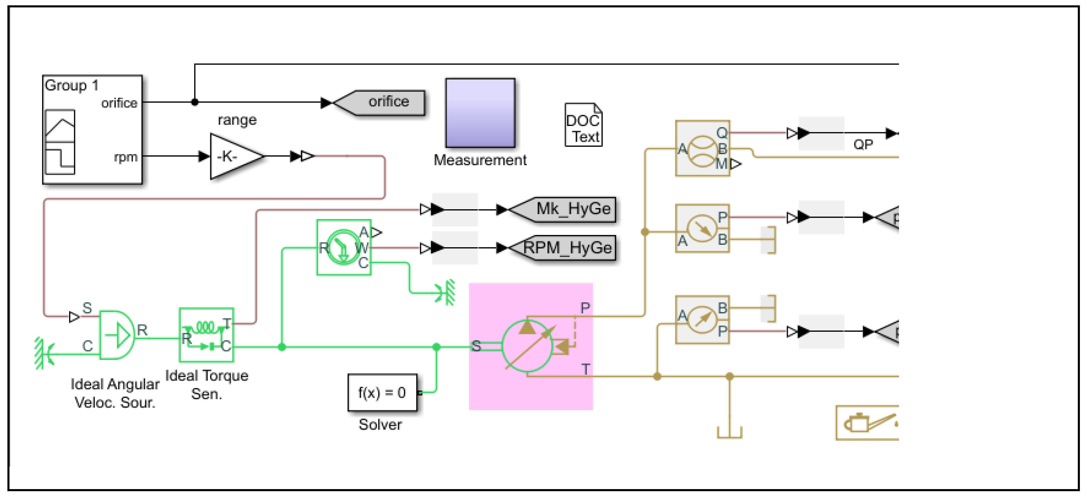
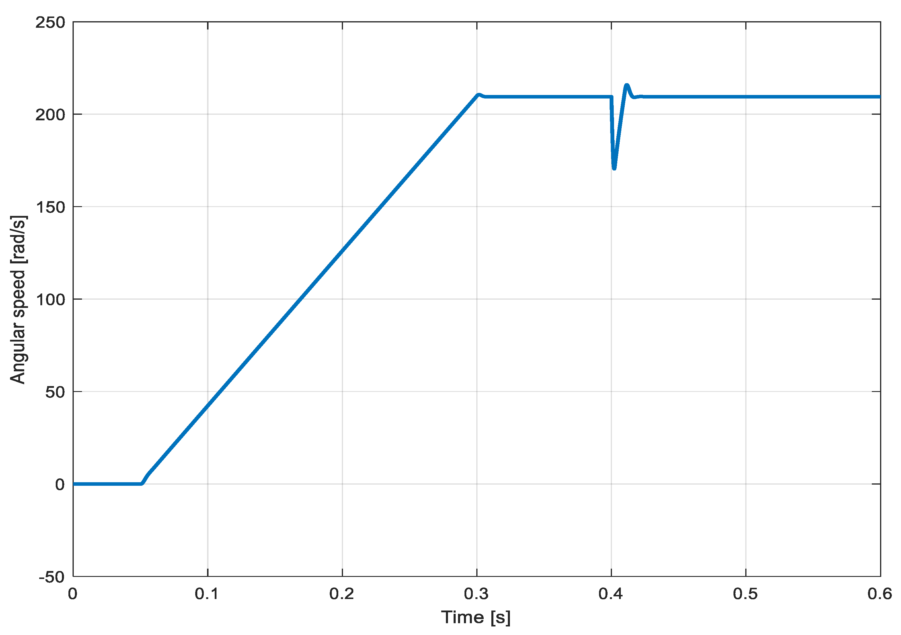
The characteristics of the electric rotary motor for the pump drive were first simulated (Figure 17) and subsequently measured. Motor acceleration went from 0 to 2000 rpm without load. In 0.4 s, a torque impulse of 0–30 Nm was applied to the motor.
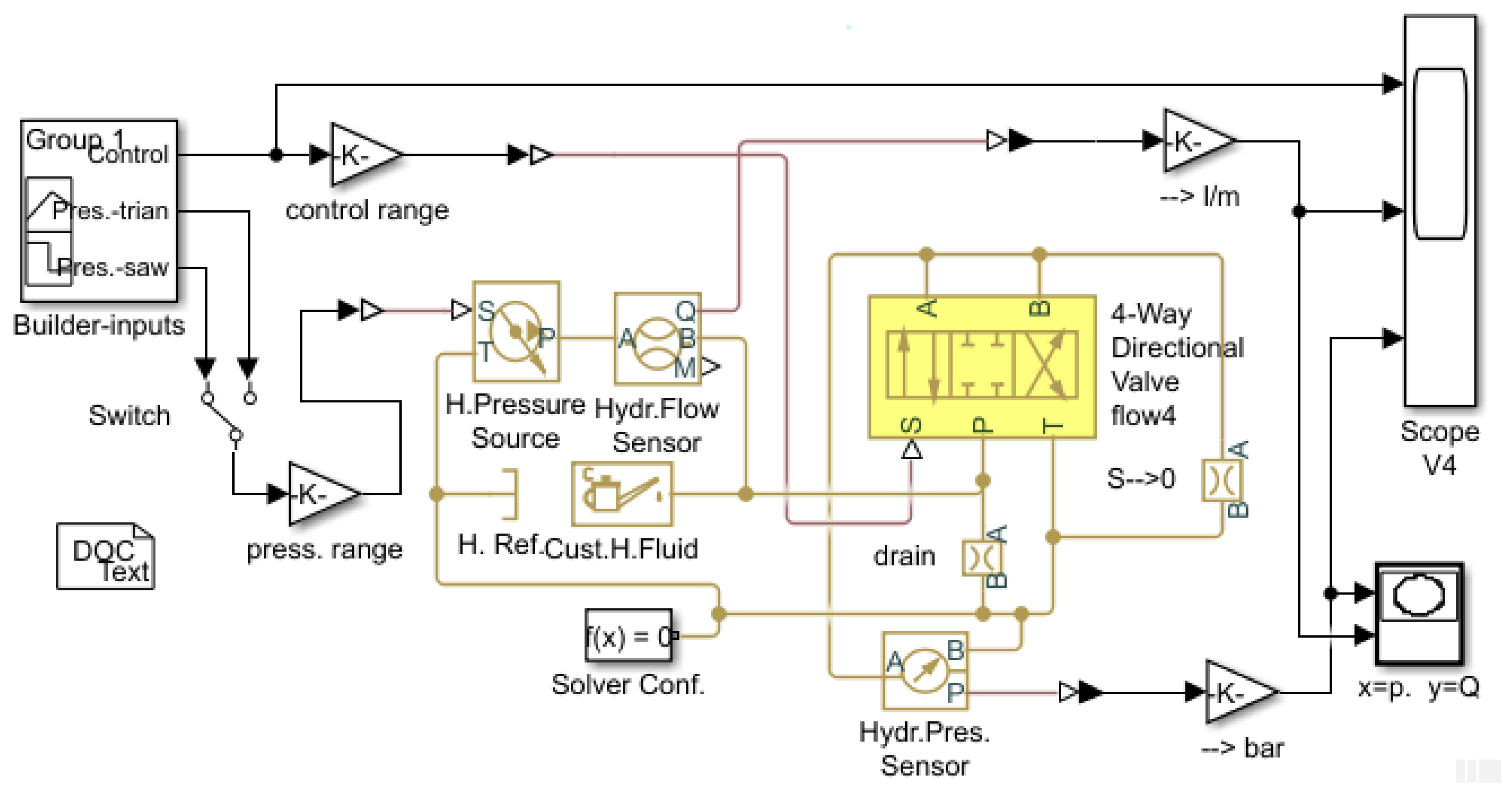
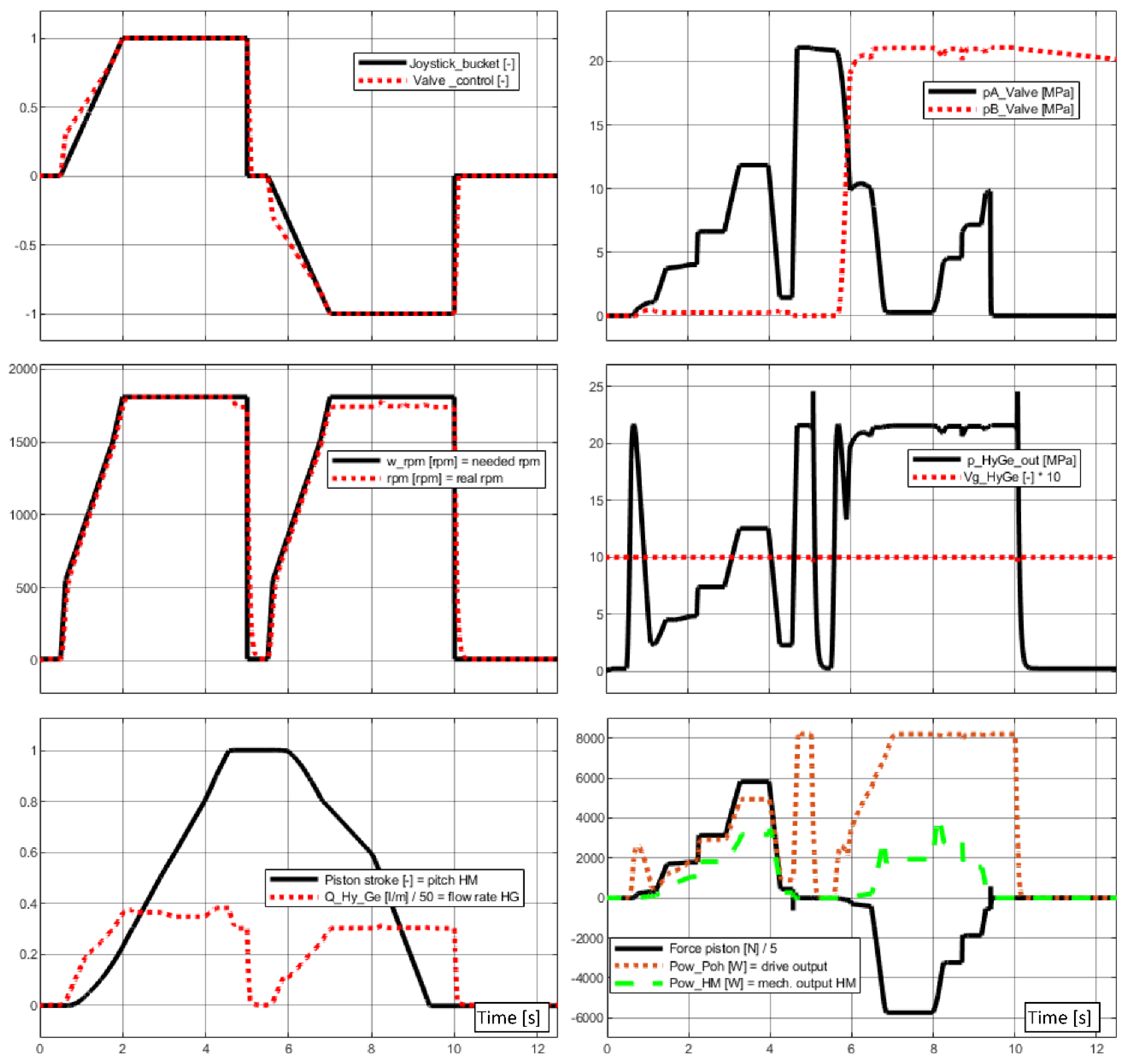
Figure 18 shows the results of the simulation of hydraulic, mechanical, and electrical quantities during several rapid movements of the excavator bucket, while the load changes stepwise almost to the maximum (force piston, max = 27,000 N for both directions of movement). The drive was already slightly overloaded (actual speed was lower than required).

8. Results

An electric drive of the excavator (Figure 19) was created with a patented control system of its subsystems, the operation of which was free of gaseous and, to a large extent, noise emissions, unlike the original drive using an internal combustion diesel engine. Functional tests show that the machine is able to operate in standard operating mode. The measured values indicate good energy utilization of the machine. With a used battery, it is possible to achieve real working performance of 7 h. It can be stated that the knowledge gained within the framework of the project is reflected in the design and development of prototype part of the excavator as well as, specifically, in the “flow sharing” block and the axial pump type A10VO, both from the company Bosch Rexroth.
The developed mathematical models can be used even after the end of the project for work on other types of similar machines (see Appendix A).

9. Discussion

The new type of drive predetermines the use of the excavator, especially for such places where operation without gas exhalations and with lowered noise otherwise emitted by internal combustion engine is required, i.e., in enclosed spaces and protected areas such as hospitals, rehabilitation facilities, protected landscape areas, etc.
The limiting factor for achieving higher perfection of the models (accuracy, reliability) is the limited availability of parameters of the modeled parts of the device. Some parameters must then be determined by expert judgment. Also, the possibilities of model verification are complicated by the fact that, currently, the measurements on a real excavator can contain only a limited number of measured quantities, some of which (mainly torque) showed a certain unreliability. The verification had to be performed by a detailed analysis of only some of the mutually corresponding parts of the measurement and simulation records.
The standard drive system of excavators powered by hydraulic motors seems to be somewhat inefficient due to the repeated conversion of energy: electric (in the case of a battery excavator)–mechanical–hydraulic–mechanical. This causes some energy losses. A direct electric drive with one conversion, electric–mechanical, could theoretically lead to an increase in drive efficiency. A change of this kind was not among the objectives of the described project, but it seems to be a potential topic for the next phase of electrification of excavators and similar machines.
A battery electric drive brings new possibilities to the field of mobile working machines for the efficient use of installed energy. The simulations and functional tests show the advantages and disadvantages of this solution.
Due to the designation of the machine for operations requiring zero gas exhalations, it is now difficult to compare its economic parameters, such as machine price, all operating costs, and return on investment, to the parameters of a standard machine with an internal combustion engine while achieving the same or longer machine life. The results of the development as mathematical models were usable not only during the solution of the project, but also after the end of the project for similar development work. The knowledge from modeling is transferable to similar applications of control of hydrostatic drives, hydraulic motors in building, earthmoving machines, and the like.

10. Patents

Proven control algorithm in the form of software and its utility model according to patent application 2018-35127. The application was submitted to the Office for the Protection of Industrial Property.

Author Contributions

Conceptualization, M.F. and M.J.; methodology, M.F.; software modeling Z.N. and P.P.; validation, P.V. and J.N.; experiments, M.J. and P.P.; writing—original paper preparation, J.N.; writing—review and editing and supervision, M.F., Z.N., and P.V.; project administration and funding acquisition, M.F. and D.K. All authors have read and agreed to the published version of the manuscript.

Funding

The TRIO project by the Ministry of Industry and Commerce of the Czech Republic in 2016–2018, project registration number: FV10411.

Conflicts of Interest

The authors declare no conflict of interest. The funders had no role in the design of the study; in the collection, analyses, or interpretation of data; in the writing of the manuscript; or in the decision to publish the results.

Appendix A. Example of Application of Methods and Models Created during the Development of the E019 Machines

The electrification of the Dapper 5000 wheel loader [23], manufactured by VOP CZ and is currently being worked on, can serve as an example of the application of methods and models created during the development of the electric version of the E19 excavator to other machines. It is again a replacement of a diesel engine drive with an electric drive, with energy supply from an electric accumulator. Even in this case, it is a working machine in which the drive of the end working parts is ensured by hydraulic motors.
Figure A1. The Dapper 5000 wheel loader.
Proceedings 58 00025 g0a1

References

  1. Bosch Rexroth. The Drive & Control Company. Bosch Rexroth AG. © BoschRexroth A. Available online: https://www.boschrexroth.com/ (accessed on 4 August 2019).
  2. Unveils An All-Electric 26-Ton Excavator with a Gia-Nt 300 Kwh Battery Pack. Available online: https://electrek.co/2019/01/29/caterpillar-electric-excavator-giant-battery-pack/ (accessed on 29 January 2019).
  3. Komatsu Ltd. Developed an Electric Battery Driven Excavator. Available online: https://home.komatsu/en/press/2019/technology/1202112_1836.html (accessed on 4 August 2019).
  4. Liebherr Mining Goes Electric. Tery-Powered Excavator. Available online: https://www.liebherr.com/En/Int/Latest-News/News-Press Releases/Detail/Liebherr-Mining-Goes-Electric.Html#Lightbox (accessed on 4 August 2019).
  5. Takeuchi Launches 4t Bat 718 Article. Wacker Neuson Unveils the EZ17e, Its First Battery-Powered Excavator. Available online: https://www.equipmentwo-rld.com/wacker-unveils-ez17e/ (accessed on 25 April 2018).
  6. Wacker Neuson Unveils the EZ17e, Its First Battery-Powered Excavator. Available online: https://www.equipmentworld.com/wacker-unveils-ez17e/ (accessed on 25 April 2018).
  7. Bobcat Rolls Out the E10e, Its First Electric Mini Excavator. Available online: https://www.equipmentworld.com/bobcat-rolls-out-the-z10e-its-first-electric-mini-excavat (accessed on 29 August 2019).
  8. Kobelco Launches Electric Mini Excavator Concept. Available online: https://www.tradelinkmedia.biz/publications/7/news/1635 (accessed on 11 June 2019).
  9. Casoli, P.; Luca, R.; Campanini, F.; Lettini, A.; Dolcin, C. Hydraulic Hybrid Excavator: Layout Definition, Experimental Activity, Mathematical Model Validation and Fuel Consumption Evaluation. In Proceedings of the 10th International Fluid Power Conference, Dresden, Germany, 19 June 2016. [Google Scholar]
  10. Vauhkonen, N.; Liljeström, J.; Maharjan, D.; Mahat, C.; Sainio, P.; Kiviluoma, P.; Kuosmanen, P. Electrification of excavator. In Proceedings of the 9th International DAAAM Baltic Conference “INDUSTRIAL ENGINEERING”, Tallinn, Estonia, 24–26 April 2014. [Google Scholar]
  11. Xu, J.; Yoon, H.-S. A Review on Mechanical and Hydraulic System Modelingof Excavator Manipulator System. Hindawi Publishing Corporation. J. Construct. Eng. 2016, 11, 9409370. [Google Scholar] [CrossRef]
  12. Nevrly, J. Methodology of Modeling Fluid Power and Lubrication Systems, 1st ed.; Wydawnictwo Politechniki Wroclawskiej: Wroclaw, Polandd, 2005; ISBN 83-7085-848-1. [Google Scholar]
  13. Nepraz, F.; Nevrly, J.; Penaz, V.; Tretina, K. Modeling of Systems Equipped with Hydraulic Mechanisms, 1st ed.; Bosch Rexroth: Brno, Czech Republic, 2002; (In Czech). ISBN 80-214-2187-8. [Google Scholar]
  14. Casoli, P.; Riccò, L.; Campanini, F.; Bedotti, A. Hydraulic Hybrid Excavator—Mathematical Model Validation and Energy Analysis. Energies 2016, 9, 1002. [Google Scholar] [CrossRef]
  15. Alvin, A. Modeling and Analysis of Hydraulic Load Sensing Strategies in Off Highway Equipment. Ph.D. Thesis, Università degli studi di Parma, Parma, Italy, 2017. [Google Scholar]
  16. Nevrly, J.; Nemec, Z.; Pazdera, I.; Nozka, M. Simulation of drive for electric-hydraulic excavator. In Proceedings of the 24rd International Conference on Hydraulics and Pneumatics, Prague, Czech Republic, 12–14 September 2018. [Google Scholar]
  17. Li, J.; Zhao, J.; Zhang, X. A Novel Energy Recovery System Integrating Flywheel and Flow Regeneration for a Hydraulic Excavator Boom System. Energies 2020, 13, 315. [Google Scholar] [CrossRef]
  18. Zhang, D.; Gong, J.; Zhao, Y.; Liu, Ch.; Hu, P.; Tang, Z. Research on a new energy-recovery system for hybrid hydraulic excavators. IOP Conf. Ser. Earth Environ. Sci. 2019, 300, 042003. [Google Scholar] [CrossRef]
  19. Jurik, M. Energy balancing for zero emission excavator. In Proceedings of the 24rd International Conference on Hydraulics and Pneumatics, Prague, Czech Republic, 12–14 September 2018. [Google Scholar]
  20. Hassi, T.; Korva, A.; Markkula, S.; Partanen, T.; Sourander, T.; Kiviluoma, P.; Korhonen, A.; Kuosmanen, P. Improving energy efficiency of an electric mini excavator. In Proceedings of the 11th International DAAAM Baltic Conference “Industrial Engineering”, Tallinn, Estonia, 20–22 April 2016. [Google Scholar]
  21. Salomaa, V.; Minav, T.; Mattila, J.; Pietola, M. Efficiency study of an electro-hydraulic excavator. In Proceedings of the International Fluid Power Conference, Aachen, Germany, 19–21 March 2018; RWTH Aachen: Aachen, Germany, 2018. [Google Scholar]
  22. Liu, X.; Sun, D.; Qin, D.; Liu, J. Achievement of Fuel Savings in Wheel Loader by applying Hydrodynamic Mechanical Power Split Transmissions. Energies 2017, 10, 1267. [Google Scholar] [CrossRef]
  23. Dapper 5000. Available online: http://www.dapper.cz/ (accessed on 29 August 2019).
Figure 1. Diesel-driven excavator E19, producer: Bobcat.
Proceedings 58 00025 g001
Figure 2. Basic block diagram of the electric drive of excavator E19.
Proceedings 58 00025 g002
Figure 3. Model of the electric motor pump drive subsystem.
Proceedings 58 00025 g003
Figure 4. Electric battery.
Proceedings 58 00025 g004
Figure 5. Parameters of the Li-Fe battery cell.
Proceedings 58 00025 g005
Figure 6. LiFePO4 battery charging control strategy.
Proceedings 58 00025 g006
Figure 7. Electrical workplace measurement.
Proceedings 58 00025 g007
Figure 8. Standard hydraulic system of the excavator.
Proceedings 58 00025 g008
Figure 9. Scheme of the hydraulic system of excavator E19.
Proceedings 58 00025 g009
Figure 10. Model of the pump connected to the hydraulic system.
Proceedings 58 00025 g010
Figure 11. Example of the model of the directional valve connection.
Proceedings 58 00025 g011
Figure 12. Location of elements in the excavator frame.
Proceedings 58 00025 g012
Figure 13. Main parts of the control system.
Proceedings 58 00025 g013
Figure 14. Block diagram of the electric excavator control.
Proceedings 58 00025 g014
Figure 15. Diagram of data flows of basic software modules.
Proceedings 58 00025 g015
Figure 16. Results of measurement of excavator system parameters during start and stop.
Proceedings 58 00025 g016
Figure 17. Simulated course of the angular velocity of the electric motor at a load of 25 Nm.
Proceedings 58 00025 g017
Figure 18. Simulation of rapid bucket movements by variable load.
Proceedings 58 00025 g018
Figure 19. Electric excavator E19 when digging.
Proceedings 58 00025 g019
Publisher’s Note: MDPI stays neutral with regard to jurisdictional claims in published maps and institutional affiliations.

