Design of a Tandem Compressor for the Electrically-Driven Turbocharger of a Hybrid City Car †
Abstract
:1. Introduction
2. The Original Turbocharged Engine
3. Rationale of the Proposed Modifications
4. The Modified Radial Compressor: Geometry and Computational Mesh
4.1. The Original GT12 Compressor Geometry
- Since the original drawings are proprietary, images and samples of existing rotors were examined to extract representative quantitative information (diameters, angles, curvatures, blade thickness, etc.) sufficient to generate a proper geometrical model and to digitalize the obtained geometries using Vista CCD;
- The virtual design thus obtained was lengthened by 1.5 diameters of the inlet eye (30 mm) on the intake side, so that the numerical code may “adjust” the flow quantities from the inlet b.c. to the blade leading edge. Similarly, the outlet was lengthened by 10% of the blade tip diameter (2 mm);
- The blade profile was generated as a cubic spline. The incidence β was specified from the geometrical drawing, and a blade overlap of θ = 60° was imposed. The splitter was set to begin at mid channel length. The blade maximum thickness is 1.3% of the chord of the blade and clearance is set to 2% of blade span.
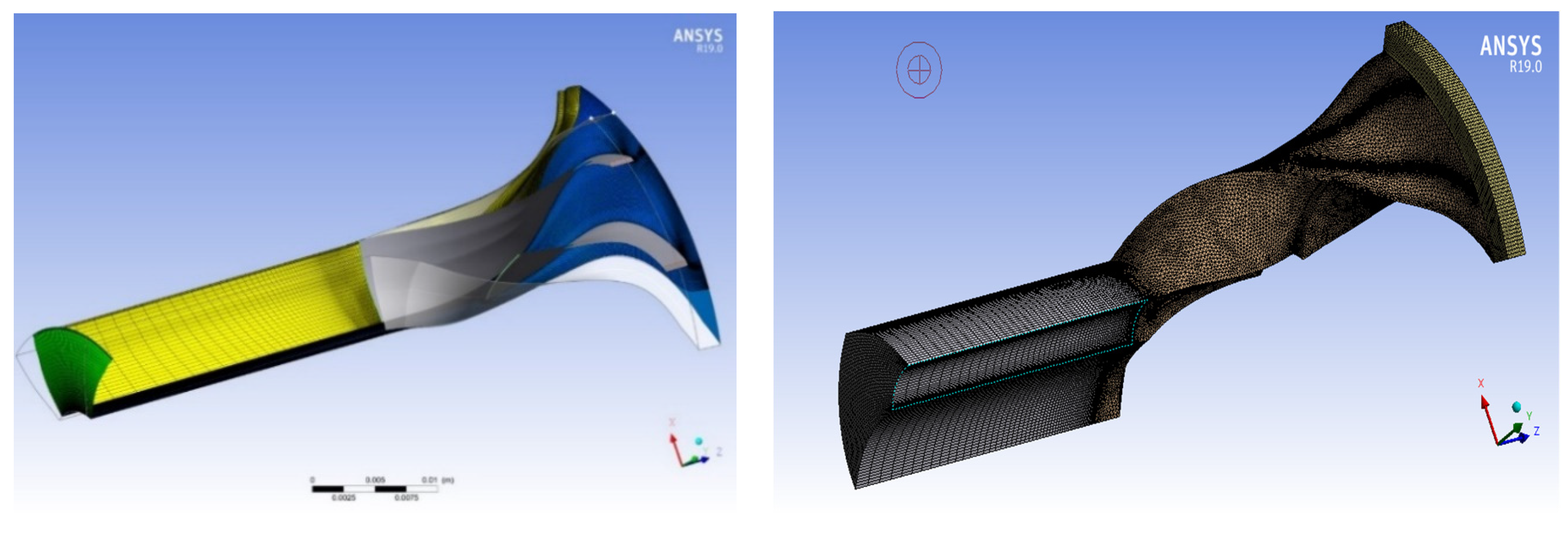
- Thanks to the axisymmetric geometry of the impeller, the computational domain consists of a 60° solid slice of the entire impeller and includes one main blade and one splitter.
4.2. The Tandem Impeller Geometry
- More accurate leading and trailing edge profiles were added to the inducer blade;
- Both the inducer chord and stagger varied spanwise;
- The inducer maximum thickness was set to 3.5% of chord and located at mid chord;
- The exducer is obtained by trimming the original centrifugal blades until they reach the same chord length as the splitter blades: in practice, we are thus dealing with a 12-blade radial rotor.
4.3. The Diffuser
5. Performance Comparisons
5.1. The Tandem Compressor
5.1.1. CFD Results
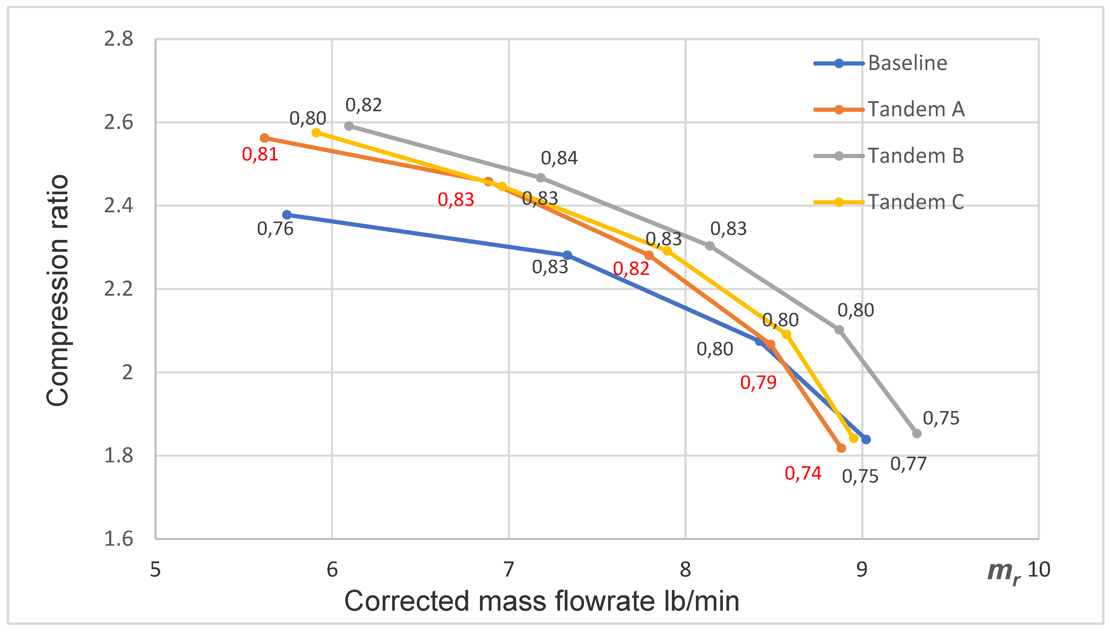
- displays a better efficiency than the Garrett compressor over the entire operating range (except very close to the choking line). This result was expected and well-documented in the relevant literature [7];
- attains higher compression ratios over the entire operating range (except very close to the choking line). This result will be justified below by a detailed examination of the flowfields;
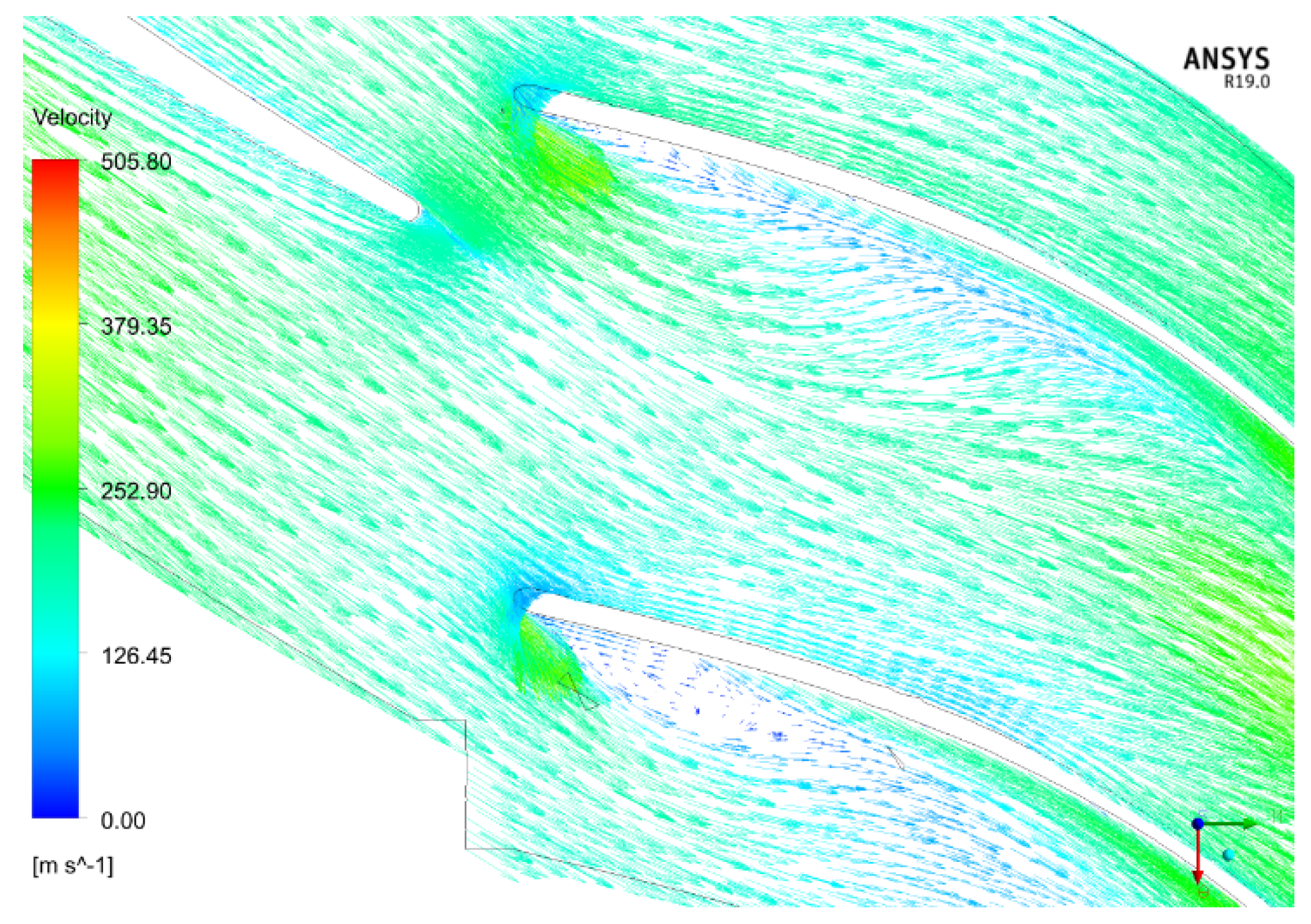
- seems to display a better resistance to stalling (the efficiency is still high at lower mass flow ratios than its standard counterpart). This result needs a more careful analysis, and will be also discussed below, by detailed examination of the flowfields.
- The inducer trailing edge and exducer leading edge were made radial, to enforce a radially constant angular gap between the two blades;
- The exducer stagger has been redesigned to match the relative fluid flow leaving the inducer cascade;
- The angular overlapping of the exducer was reduced to 40°, to increase the critical mass flowrate.
- “Tandem B”: 75% clock and 0.5 mm of axial clearance, overlap 40°. Obtained by a design of experiment (DOE) campaign;
- “Tandem C”: 75% clock and 0.5 mm of axial clearance, overlap 50°.
5.1.2. Discussion
6. Maps of the Entropy Generation Rate
7. Conclusions
Funding
References
- Hu, B.; Turner, J.W.G.; Akehurst, S.; Brace, C.; Copeland, C. Observations on and Potential Trends for Mechanically Supercharging a Downsized Passenger Car Engine: A Review. Proc. Inst. Mech. Eng. Part D J. Automob. Eng. 2017, 231, 435–456. [Google Scholar] [CrossRef]
- Patil, C.; Sanjyot, V.; Swapnil, W. A Review of Engine Downsizing and Its Effects. Int. J. Curr. Eng. Technol. 2017, 7, 319–324. [Google Scholar]
- Capata, R. New Power Train Concept for a City Hybrid Vehicle. In Proceedings of the WEF-1 International Conference, Roma, Italy, 14 September–5 October 2020. [Google Scholar]
- Muqeem, M.; Manoj, K. Turbocharging of IC engines: A review. Int. J. Mech. Eng. Technol. IJMET 2013, 4, 142–149. [Google Scholar]
- Heywood, J.B. Internal Combustion Engine Fundamentals; McGraw-Hill Education: New York City, NY, USA, 2016. [Google Scholar]
- Erdmenger, R.R.; Michelassi, V. Influence of Tandem Inducers on the Performance of High Pressure Ratio Centrifugal Compressors, ASME Paper GT2015-43001. In Proceedings of the ASME Turbo Expo 2015: Turbine Technical Conference and Exposition Proceedings, Montreal, QC, Canada, 15–19 June 2015. [Google Scholar]
- Hanus, D.; Censky, T.; Neveceral, J.; Horky, V. First stage of the centrifugal compressor design with tandem rotor blades. In Proceedings of the ISABE-17th International Symposium on Airbreathing Engines, Munich, Germany, 4–9 September 2005; Paper 1161. [Google Scholar]
- Hlavá, D.; Hanus, D. Results of the Development of a Tandem-Bladed Centrifugal Compressor Stage. Studentská Tvůrčí Činnost, 2016. Available online: http://stc.fs.cvut.cz/pdf16/6520.pdf (accessed on 1 March 2019).
- Qureshi, S.R.; El-Leathy, A.; Ud-Din, K.S.; Umer, U.; Chaochen, M.; Danish, S.N. Numerical Investigation and Comparison of a Tandem-Bladed Turbocharger Centrifugal Compressor Stage with Conventional Design. Int. J. Therm. Sci. 2014, 23, 523–534. [Google Scholar]
- Silvestri, T. CFD Analysis of a Radial Turbine Stage with Variable NGV Control. Master’s Thesis, University of Roma Sapienza, Roma, Italy, 2020. [Google Scholar]
- Cuturi, N. CFD Analysis of a Radial Compressor Stage with Inducer Blades. Master’s Thesis, University of Roma Sapienza, Roma, Italy, 2019. [Google Scholar]
- Mohtar, H. Increasing Surge Margin of Turbocharger Centrifugal Compressor Automotive. Ph.D. Thesis, Ecole Centrale de Nantes, Nantes, France, 2010. [Google Scholar]
- Bejan, A. Entropy Generation through Heat and Fluid Flow, 1st ed.; J. Wiley & Sons, Inc.: Hoboken, NJ, USA, 1982. [Google Scholar]
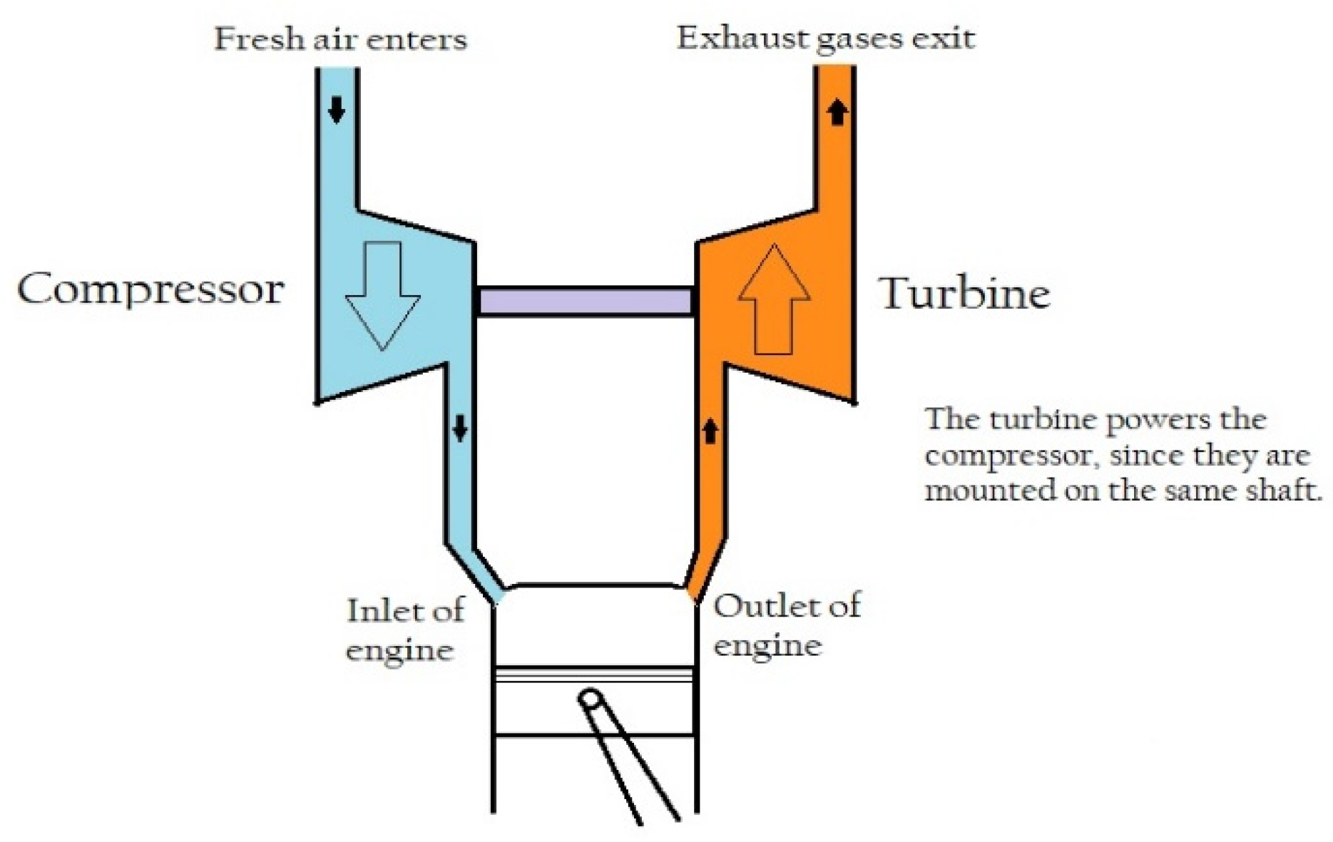

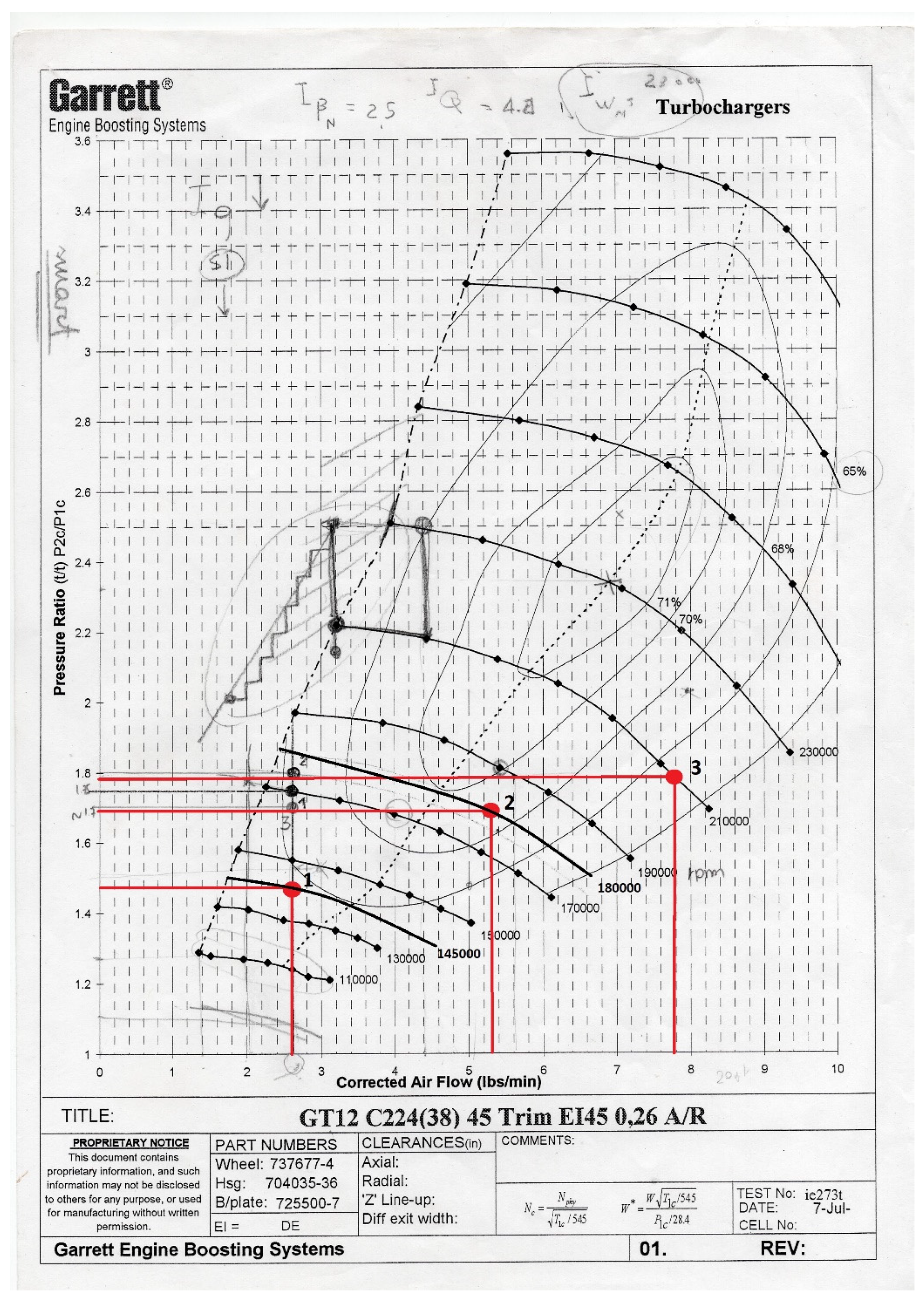

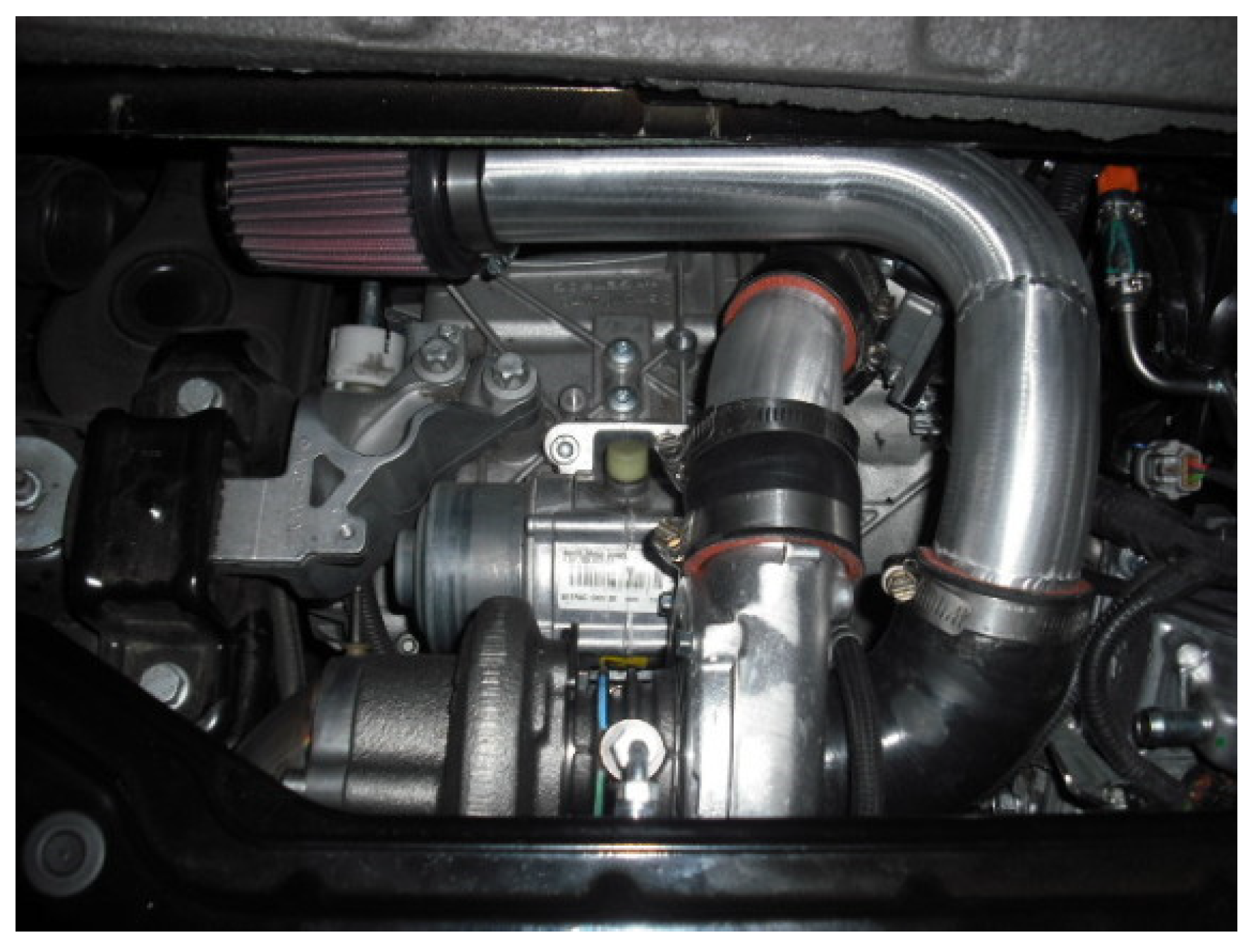

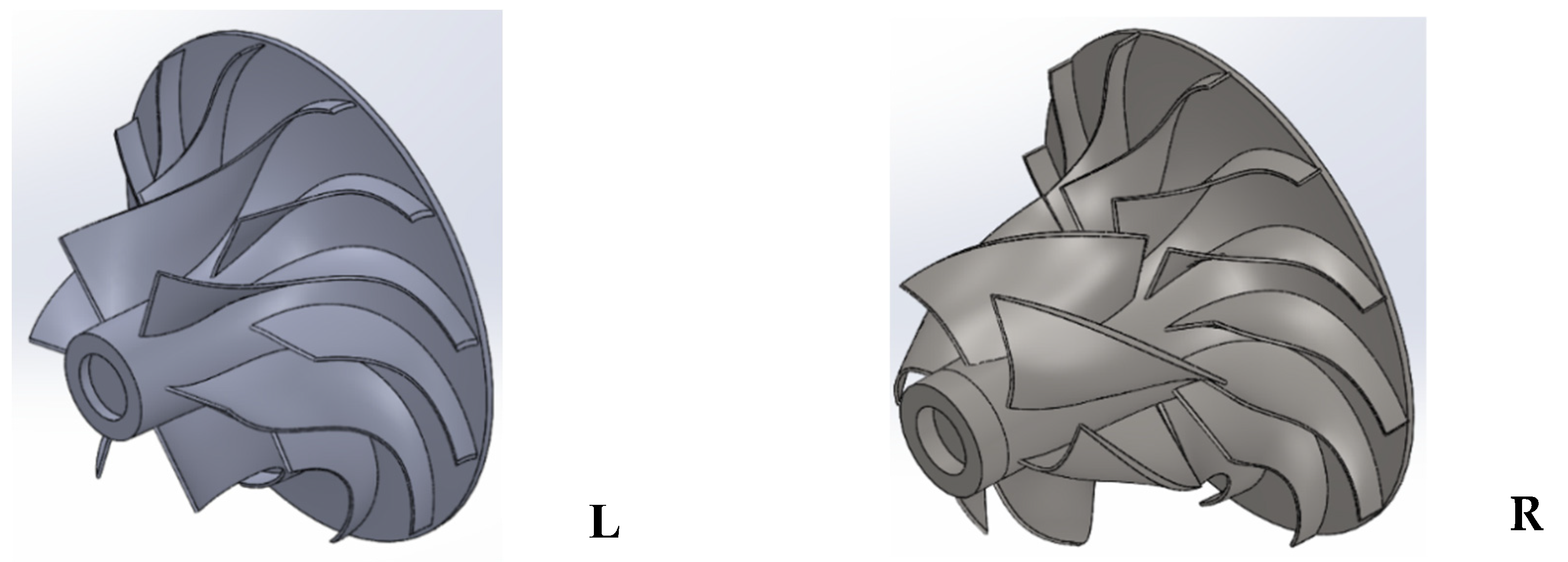



| Inlet Pressure (p1) | Pa | 101000 |
| Inlet temperature (T1) | K | 298 |
| Intake mass flow rate, point 1 | [kg/s] | 0.021 |
| Intake mass flow rate, point 2 | [kg/s] | 0.042 |
| Intake mass flow rate, point 3 | [kg/s] | 0.062 |
| Corrected mass flow, point 1 | [lb/min] | 2.7 |
| Corrected mass flow, point 2 | [lb/min] | 5.2 |
| Corrected mass flow, point 3 | [lb/min] | 7.8 |
| Unit | Value | |
|---|---|---|
| Inducer tip diameter (D1) | mm | 22.47 |
| Inducer hub diameter (D1i) | mm | 8.20 |
| Exducer tip diameter (D2) | mm | 38.00 |
| Blade tip span (b) | mm | 2.38 |
| Zn | - | 6 + 12 |
Publisher’s Note: MDPI stays neutral with regard to jurisdictional claims in published maps and institutional affiliations. |
© 2020 by the authors. Licensee MDPI, Basel, Switzerland. This article is an open access article distributed under the terms and conditions of the Creative Commons Attribution (CC BY) license (https://creativecommons.org/licenses/by/4.0/).
Share and Cite
Cuturi, N.; Sciubba, E. Design of a Tandem Compressor for the Electrically-Driven Turbocharger of a Hybrid City Car. Proceedings 2020, 58, 24. https://doi.org/10.3390/WEF-06934
Cuturi N, Sciubba E. Design of a Tandem Compressor for the Electrically-Driven Turbocharger of a Hybrid City Car. Proceedings. 2020; 58(1):24. https://doi.org/10.3390/WEF-06934
Chicago/Turabian StyleCuturi, Nicolò, and Enrico Sciubba. 2020. "Design of a Tandem Compressor for the Electrically-Driven Turbocharger of a Hybrid City Car" Proceedings 58, no. 1: 24. https://doi.org/10.3390/WEF-06934
APA StyleCuturi, N., & Sciubba, E. (2020). Design of a Tandem Compressor for the Electrically-Driven Turbocharger of a Hybrid City Car. Proceedings, 58(1), 24. https://doi.org/10.3390/WEF-06934


