Abstract
The energy production future is dominated by renewable energy sources driven by global warming problems and aiming at the reduction of fossil fuel dependence. Wind energy is becoming competitive with fossil fuels considering its less price and less CO2 emission production. Wind turbines consist of different types, including Doubly Fed Induction Generator (DFIG) which is a variable speed wind turbine and operates at varying speeds corresponding to the varying wind speeds from the cut-in speed through the rated wind speed to the cut-out speed. In the case of grid failure, the network voltage drops; consequently, the rotor current and DC link voltage increase which leads to damage of the rotor windings and power electronics device. Some protections are applied to the machine in order to help the Low Voltage Ride-Through (LVRT) ability of the doubly fed induction generator. In this root, the crowbar protection circuit is used widely in wind power plants. However, crowbar protection should be sized carefully due to its effects on both DC link voltage and rotor currents. In this paper, a doubly fed induction generator with crowbar protection is studied and the optimum value for the crowbar protection is derived; then, a Simulink model of a doubly fed induction generator protected by a crowbar protection is developed and used to analyze the effect of crowbar protection value on the DC link voltage and rotor currents. The results show a significant improvement in the LVRT ability of the DFIG.
1. Introduction
The energy production future is dominated by renewable energy sources (RES); less CO2 production, availability in most of the locations, and being an endless source of energy are among the reasons to replace fossil fuel plants with RESs. Among the possible renewable energy sources, wind power generation is one of the most attractive options due to its availability in different areas and economical large-scale power production. The wind turbine generators are mostly doubly fed induction generators since they are less expensive, have higher efficiency even at low wind speeds, and have decoupled control of active and reactive power. However, because of the direct connection of the stator to the grid, they are vulnerable to the grid voltage dips. In case of severe voltage dips, a hardware protection system is preferred rather than control strategies; crowbar protection is the most widely used protection system in order to ensure the low voltage ride-through ability of the DFIGs. However, the crowbar protection should be sized carefully; if the value is low, the fault current through the rotor windings is higher than its safe limits which damages the windings, while a high value of crowbar protection may lead to the DC link capacitor over voltage and its breaking.
In this paper, a safe range for the crowbar protection is derived, and a MATLAB/Simulink model of a grid connected DFIG is developed in order to study the effect of the crowbar protection value on the rotor currents and DC link voltage during a grid voltage dip.
2. DFIG under the Fault with Crowbar Protection
DFIG is a variable speed wind turbine and operates at varying speeds corresponding to the varying wind speeds from the cut-in speed (the wind speed at which the blades start to rotate) through the rated wind speed (the wind speed at which the maximum generator power is can be extracted from the wind) to the cut-out speed (the wind speed at which the turbine should be shut down to prevent damages to the wind turbine).
2.1. DFIG Components
Figure 1 shows the DFIG scheme which consists of the rotor side converter (RSC), the grid side converter (GSC), and the DC link capacitor as the power electronic device components. Since the rotor circuit power is about 30% of the stator circuit, the cost of the power electronics is much less if they are being used in the rotor circuit rather than the stator circuit (direct-in-line adjustable speed generators).
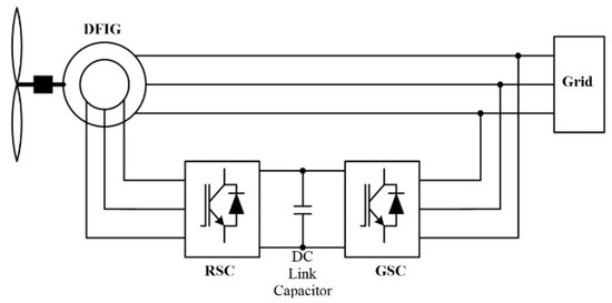
Figure 1.
DFIG configuration.
2.1.1. RSC Controller
Figure 2 shows the overall RSC controller scheme. The rotor side converter has to apply the voltage to the DFIG rotor windings; The rotor-side converter utilizes a torque controller for the regulation of the wind turbine output power and stator terminal voltages. The power control is done according to the turbine power-speed characteristics in order to track the maximum power point. The wind turbine characteristics is used to provide the reference power which is the reference for the sum of the total power losses and generator electrical output power. A Proportional-Integral (PI) regulator is used for the reduction of the power error down to zero. The PI regulator’s output is the reference rotor current that must be injected to the rotor windings by the rotor-side converter. The electromagnetic torque is controlled by the q-axis component; therefore, the actual q-axis component of the rotor current,, should be compared to the reference q-axis component of the rotor current, , and the difference should be kept down to zero by a current PI regulator.
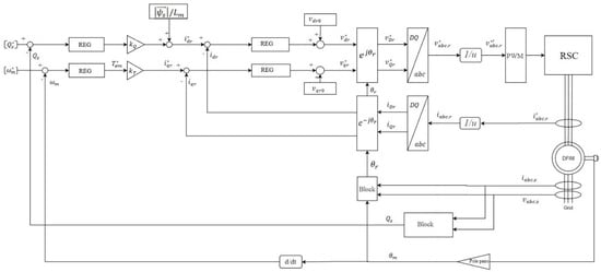
Figure 2.
RSC controller scheme [1].
The output of the controller is the voltage,, generated by the rotor-side converter. Therefore, in a similar way, with the regulation of the d-axis component of the rotor current, , and , the required three-phase voltages applied to the rotor windings are obtained.
2.1.2. GSC Controller
The grid side converter has to keep the DC link voltage constant and regulate the reactive power exchange for the voltage support requirements. The DC link voltage control,, and the reactive power exchange between the GSC and the grid is shown in Figure 3 which show the overall vector control scheme of the GSC. The control scheme consists of two control loops. The outer control loop is responsible for the DC link voltage regulation whose output is the d-component reference current, for the inner loop current regulator; the is responsible for the q-component reference current,, for the inner loop current regulator. The d-axis component of the current is used to regulate the DC link voltage, and the q-axis component of the current is used to regulate the reactive power. The outputs are compensated by their corresponding terms, and , in order to form the voltage signals. Further, the modulator generates the GSC gate control signals [2].
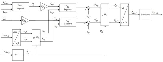
Figure 3.
GSC controller scheme [3].
2.2. Fault Current
In the case of severe voltage dip, a hardware protection system is preferred, rather than control strategies, due to its quick response. Crowbar is most widely used to protect DFIGs and ensure their LVRT ability. In case of fault, the crowbar protection connects to the rotor and the model of the DFIG will be as Figure 4. where is the differential operator; , , , are the stator and rotor resistance and leakage inductances; is the magnetizing inductance; and are the stator and rotor currents, respectively; and are the stator and rotor flux linkages, respectively; is the crowbar resistance.
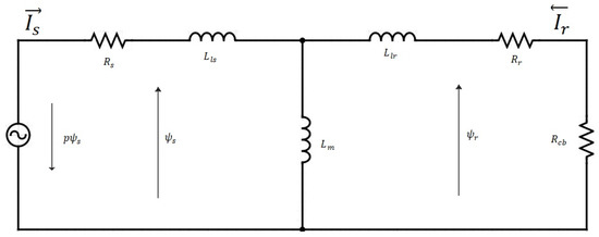
Figure 4.
Equivalent circuit of DFIG with crowbar protection [4].
The stator voltage and flux can be written as:
Usually, the value of the crowbar resistance is much more than and , and leakage inductances of the stator and rotor side are negligible compared to the magnetizing inductance. Therefore, the stator and rotor equivalent total resistance of the DFIG are:
And:
where:
According to (2) and (3), it is possible to derive stator and rotor transient time constants:
has a relatively large value and has the most effect on the value of the transient time constants; it is obvious that has a greater influence on the rotor transient time constant; thus, it is much less than the stator transient time constant.
The faulty stator current of three-phase short circuit is obtained in the synchronously rotating reference frame as the follow [4]:
where β is the angle between and d-axis; is the initial stator flux after dip occurs.
Under the assumption that the voltage dip to zero at , the transient stator flux can be written as [4,5]:
When the voltage dip occurs, according to the flux linkage conservation principle, the stator and rotor flux linkages cannot suddenly change; therefore, the initial value of the stator flux, , is the same as the steady state value.
The rotor transient time constant is much less than the stator transient time constant; therefore, the rotor transient component decays faster and the amplitude of the current is determined by the stator transient time constant. Thus, the maximum fault current can be written as:
2.3. Calculation on the Crowbar Resistance
Equation 8 shows the relation between the crowbar resistance and the fault current. Lower crowbar resistance will not limit the current and will weaken the LVRT of the DFIG; additionally, the fault current should be limited by increasing the crowbar resistance in order to protect the rotor windings from over current. With bigger crowbar resistance, the DC link over voltage may occur which should be avoided in order to protect it from breaking. Therefore, the crowbar resistance should be sized carefully to ensure the LVRT behavior of the DFIG.
The maximum value of the fault current should retain less than the rotor safe current to protect the windings from the damage, consequently:
where , is the rotor safe current.
On the other hand, with increasing value of the crowbar resistance, the voltage at the rotor side of the back to back converter will increase, the diode bridge will turn on, and the DC link overvoltage will occur; thus, the maximum value of the crowbar resistance should be limited by the voltage bearing capability of the DC link in order to improve the LVRT capability.
where is the maximum allowable voltage at the DC link.
Therefore, the value of the crowbar resistance is determined by equations 9 and 10.
3. Results
A single machine model of a DFIG system has been developed in MATLAB/Simulink with abovementioned control strategies and a crowbar protection in order to study the impact of the crowbar protection on LVRT behavior of the DFIG. The parameters are shown in Table A1 in the appendix. The values of the crowbar protection with respect to the rotor are chosen to be 100, 400, and 1700 times of the rotor resistance. Figure 5 shows the characteristics of the fault. The voltage dips to the value of 10% of the nominal voltage at second 3 and starts to linearly recover from second 3.5 to 4.
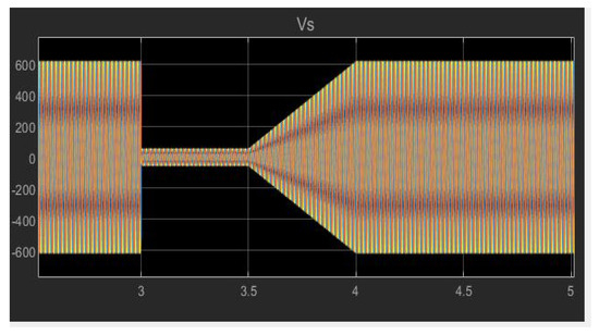
Figure 5.
Fault characteristics.
3.1. DFIG without Crowbar Protection
At second 3, the fault occurs and the voltage dips to 0.1 of the steady state value; meanwhile, the rotor currents rise to a higher value and the DC link voltage start to rise as is expected. Since the rotor currents have no other root to go through, they go through the RSC.
The stored energy in the DC capacitor can be defined as:
where is the capacitance, is the voltage of the DC link, is the stored energy, and is the input power to the DC link. The voltage and energy derivatives are:
The is calculated as:
where is the input power from the rotor-side converter and is the grid-side converter output power. The DC link voltage varies with and is constant when .
Figure 6 represents the overall waveforms of the studied parameters.
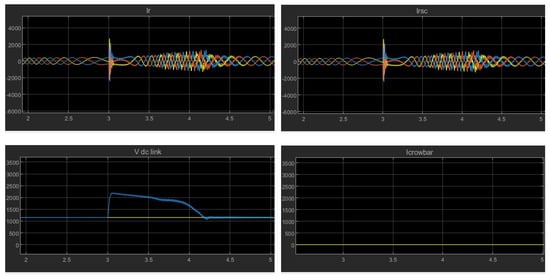
Figure 6.
DFIG’s response to the fault without protection.
The maximum rotor current at the instant of fault rises to about 6.2 times the steady state operation. Such high current can damage both the rotor windings and the power electronic device. So, this value should be damped by adoption of an optimal crowbar resistance. As is expected, the current waveforms of the rotor-side converter current and rotor currents are the same.
The excess current in the rotor side will charge the DC link capacitor through the rotor-side converter proportional to the fault time interval length; the maximum DC link voltage during fault to the steady state operation DC link voltage is about 1.9; if the voltage goes high enough, it may breakdown the capacitor which also can be suppressed by the selection of an optimal crowbar resistance.
The RSC current waveform is the same as the rotor current waveforms and the crowbar protection current remains zero in case of no crowbar protection.
3.2. DFIG with Crowbar Protection
Figure 7 shows the LVRT behavior of the DFIG with crowbar protection; the value of the protection is in ascending order from left to right.
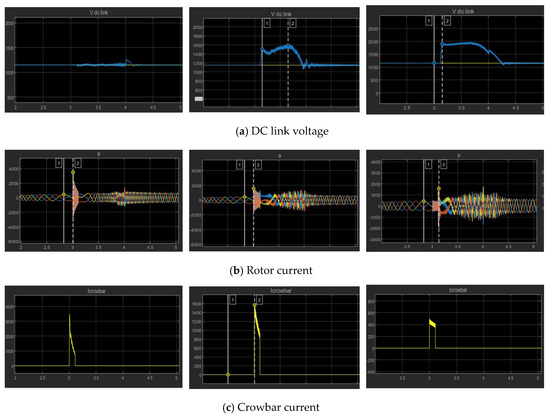
Figure 7.
DFIG’s response to the fault with crowbar protection. (a) DC link voltage; (b) Rotor current; (c) Crowbar current.
Figure 7a shows a slight change in the value of the DC link voltage with low crowbar protection, about 5% of the steady state value according to measurements and was expected. The DC link voltage waveform during fault with optimal crowbar protection shows the maximum DC link voltage to the steady state operation DC link voltage of 1.38; 38% of overvoltage, compared to the 92% of overvoltage in case of having no crowbar protection shows the reduction of 54%, which keeps the DC link voltage within an allowable range. In case of higher crowbar protection, the DC link voltage peak is 1.65 times of the steady state operation. In addition, the system recovery time takes longer with high crowbar protection value.
Figure 7b shows the impact of the crowbar resistance to rotor fault currents which limits it to a safe range acceptable by the machine. Low crowbar protection results in a high overcurrent in the rotor currents which has a maximum value of eight times the maximum value of the steady state rotor current. This will damage the rotor windings during fault. The rotor-side converter is protected due to the activation of the crowbar; However, since the protection is only limited to the rotor-side converter and the rotor currents are not damped, it is not effective and other values of the crowbar resistance should be implemented. With increasing the crowbar protection, a slight overcurrent in the rotor currents is seen.
Finally, Figure 7c shows the crowbar current waveform during its activation time; the value of the crowbar peak current is directly related to the value of the crowbar.
In the crowbar activation time interval, the back-to-back converter is disactivated which means the machine is not working as a doubly fed induction generator, therefore, it will be absorbing reactive power from the grid. Therefore, the activation time of the crowbar is another critical parameter of the crowbar protection. The machine is not fully controlled during the crowbar activation, and it is not possible to generate reactive power which is needed by the grid codes. On the other hand, less crowbar connection time interval, when the stator flux is still too high, might cause overcurrent in the rotor or DC link capacitor overvoltage. The connection time interval must compromise between the two. It should be noticed that the waveforms return back to the normal operation profile slower with increasing the crowbar protection.
4. Conclusion
In this paper, vector control strategy of the doubly fed induction generator is presented alongside with crowbar protection analysis and three-phase fault condition analysis. The results show the increase in rotor current and peak currents occur at the fault occurrence, rotor-side converter connection and fault clearance instants. Additionally, the overvoltage in the DC link capacitor is observed. The rotor current peaks have been damped after including the crowbar resistance and is damped further by increasing the value of the crowbar protection; however, by increasing the value of the crowbar protection, the overvoltage at the DC link is increased which should be avoided. Therefore, smaller crowbar resistance will weaken limitation of the short circuit current, which is harmful for the rotor windings, while, with bigger crowbar resistance, DFIG will face an overvoltage in the DC link which also should be avoided. Thus, choosing the protection is critical and should be chosen crucially.
Appendix A
Table A1 shows the DFIG important parameters.

Table A1.
DFIG parameters.
Table A1.
DFIG parameters.
| Parameter | Value | Parameter | Value |
|---|---|---|---|
| Rated power | 2 MW | Rotor leakage inductance | 0.00038 p.u. |
| Rated voltage | 690 V | Rotor resistance | 0.113 p.u. |
| Stator leakage inductance | 0.00038 p.u. | Pole pairs | 2 |
| Stator resistance | 0.0105 p.u. | DC link capacitance | 0.075 p.u. |
| Stator and rotor mutual inductance | 0.0105 p.u. | Frequency | 50 Hz |
References
- Haitham, A.-R.; Mariusz, M.; Kamal Al-H. Properties and Control of a Doubly Fed Induction Machine in Power Electronics for Renewable Energy Systems, Transportation and Industrial Applications. IEEE 2014, 270–318. [Google Scholar] [CrossRef]
- Qu, L.; Qiao, W. Constant Power Control of DFIG Wind Turbines with Supercapacitor Energy Storage. IEEE Trans. Ind. Appl. 2011, 47, 359–367. [Google Scholar] [CrossRef]
- Gonzalo, A.; López, J.; Rodríguez, M.; Marroyo, L.; Iwanski, G. Back-to-Back Power Electronic Converter in Doubly Fed Induction Machine: Modeling and Control for Wind Energy Generation Applications. IEEE 2011, 87–154. [Google Scholar] [CrossRef]
- Sun, L.; Yang, P.; Wang, Y. Simulation research for LVRT of DFIG based on rotor active crowbar protection. In Proceedings of the International Conference on Sustainable Power Generation and Supply (SUPERGEN 2012), Hangzhou, China, 8–9 September 2012; pp. 1–7. [Google Scholar] [CrossRef]
- Lopez, J.; Sanchis, P.; Roboam, X.; Marroyo, L. Dynamic Behavior of the Doubly Fed Induction Generator during Three-Phase Voltage Dips. IEEE Trans. Energy Convers. 2007, 22, 709–717. [Google Scholar] [CrossRef]
Publisher’s Note: MDPI stays neutral with regard to jurisdictional claims in published maps and institutional affiliations. |
© 2020 by the authors. Licensee MDPI, Basel, Switzerland. This article is an open access article distributed under the terms and conditions of the Creative Commons Attribution (CC BY) license (https://creativecommons.org/licenses/by/4.0/).