Proceeding Paper

Influence of Plate Orifice in the Pre-Mixing of Gas-Powered Water Heaters †

by
Roberto Magalhães
1,
Senhorinha Teixeira
2,*,
Manuel Ferreira
1 and
José Teixeira
1
1
MEtRICs Research Centre, University of Minho, 4800-058 Guimarães, Portugal
2
ALGORITMI Research Centre, University of Minho, 4800-058 Guimarães, Portugal
*
Author to whom correspondence should be addressed.
Presented at the First World Energies Forum, 14 September–5 October 2020; Available online: https://wef.sciforum.net/.
Proceedings 2020, 58(1), 17; https://doi.org/10.3390/WEF-06930
Published: 12 September 2020
(This article belongs to the Proceedings of The First World Energies Forum—Current and Future Energy Issues)

Abstract

:
Amongst the various alternatives for hot water production for domestic use, instantaneous heaters are still widely used in many markets such as the Portuguese market. In this system, a gas boiler converts the chemical energy of the gas (Liquefied Petroleum Gas, Natural Gas) to a water stream, as it is used. The complexity of such devices ranges from those with a natural convection to those with full pre-mixing of the air-fuel. The tightening of the legislation targeting these appliances is promoting an increase in efficiency, pollutant emission reduction and an increase in the safety features. The purpose of this work was to test the thermal performance of a water heater prototype with 22 kW of nominal heat output, running on Propane. Changes were made to the plate with orifices that limit the air supply to the burner flutes, where the pre-mixture with the fuel is partially made. Four different plates with different orifice diameters were built and tested in real case scenarios, taking into special consideration the pollutant emission and the fuel consumption verified. From the results, it was concluded that the best configuration in terms of efficiency is the original one, followed by the “−0.5 mm” and “−1 mm” plates. On the other hand, the best plate in terms of CO emission was the “−1 mm” plate. Concerning the plates with larger diameters to the manufacturer’s original configuration, flame instability was verified as a result of the greater primary airflow. Under the same test conditions, it was noted that the introduction of a nozzle into the fan inlet led to the suction of a larger amount of air. Finally, it was also concluded that the reduction in the orifice diameters of the plates reduces the split of primary air, resulting in an increased pressure drop in the flutes and in the overall pressure drop of the system.

1. Introduction

Water heating is a major source of energy consumption in a residential building and may account between 11% in the USA up to 32% in South Africa, of the total energy consumption [1,2]. There are various alternatives for this basic purpose and they include: electrical heating, solar panels, oil fired boilers, biomass and heat pumps. All these alternatives are often coupled with storage to take advantage of energy availability (solar), preferential tariffs (electricity) or to compensate the thermal inertia of the heat source (biomass, coal and oil). An alternative, avoiding storage, are instantaneous hot water devices, which provide hot water on demand. These are usually gas powered (Natural Gas, propane, butane) with a thermal output in the range of 20–25 kW. The method of choice depends on the energy source available, cost and, to some extent, the historic background of the specific market.
The instantaneous route has some advantages, namely: hot water is always available, there are no standby losses, and the compactness and robustness of the device [2]. The investment cost per kW compares favorably with other alternatives. The major disadvantages may include the use of non-renewable energy sources, a minimum threshold for activation and the limited level of instantaneous hot water which may be a limiting factor for multiple simultaneous use. Nonetheless, in some markets (e.g., Portugal), it is still the method of choice for a large majority of households without central distribution of hot water. The market is approximately of 300,000 units per year while in the EU it is over 1.5 M units. In addition to low investment cost, these boilers take advantage of the low cost of Natural Gas (NG) in urban areas and the distribution of propane/butane in 11–13 kg bottles in remote areas of the country; therefore, the operating costs are also competitive [2]. Although this technology has some relevance in both Europe and Asia, it has a residual market share in the USA [3].
Such boilers are available with varying levels of sophistication. The simpler ones use a partial pre-mixed burner, operate at atmospheric conditions and the secondary air is drafted into the combustion chamber by a pressure differential in the exhaust stack. Such a design (based on a late 19th century long patent by Hugo Junkers) leads to a bulky design (long diffusion flames and non-compactness to avoid large pressure drop in the heat exchanger—typically 1 Pa). They also operate at a fairly constant heat load and the emissions are dependent upon the chimney design. CO formation is always a cause of concern. On the other side of the spectrum, the fully premixed variety uses a fan to adjust the total air flow to the fuel in a plenum chamber and the air/fuel mixture is ignited on top of a perforated plate. The operation conditions are adjusted to the desired thermal load and emissions are usually very low. They are also very compact and fully enclosed which means that they can operate outdoors (a requirement for the Japanese market). On the other hand, the cost is much higher that the naturally ventilated variety.
Although this technology is fairly mature, the ever-stringent regulations for emissions and efficiency has been the main motivation for recent research in this field.
Computational Fluid Dynamics (CFD) techniques have been applied to understand and improve the performance of water heaters [4]. The authors developed a CFD model to simulate the partial pre-mixed burner in a 24-kW water heater. They assessed the influence of geometry (orifices in the burner) and operating conditions on the emissions. The authors found that when increasing the primary/secondary air ratio the CO emissions decrease while the NOx increases due to the thermal route for NOx formation. The results were compared favorably with experimental data.
Models have also been developed to assess the real impact in energy consumption. Johnson and Morrison [5] developed a lump heat capacity model to predict the energy consumption of tankless water heaters. It includes a step response and initial impulse model, a decay function and heat losses. An experimental test program was used to calibrate the model and the results were tested with field data.
Novel concepts also include the combination of gas burners with heat pumps and even Organic Rankine Cycles (ORC). Li [6] developed a parallel loop hybrid system with the combination of a heat pump and a gas fired water heater in one device, which is presented as a sustainable alternative to alleviate environment issues. Based on a thermal model for the hybrid plant, a control strategy was devised. Depending on the climate conditions, savings between 10 and 60% can be expected.
Another route can be based on the fuel side by enriching natural gas with hydrogen [7]. The authors investigated the limits of hydrogen addition without disrupting the performance of a natural gas water heater in terms of ignition, emissions and flame stability. The authors found that up to 10% could be added to the NG fuel. At this point issues in the re-ignition were observed. Because of the higher water vapor content in the flue gases, the emissions on a dry basis compare unfavorably with those without H2 addition, although CO and unburnt HC were lower.
The safety of instantaneous water heaters is a major source of concern, particularly in the effects on the indoor air quality resulting from the inflow of flue gases into the household [8]. Field trials were performed in two pilot plants representing typical households. The authors proposed methodologies for improving their performance and evaluated the influence of the wind on their operation.
The determination of reliable and accurate efficiency parameters for gas boilers has been investigated looking at the measurement setup and devices for determining their efficiency. The study looked at the measurement devices, their location within the test setup and the measurement strategy. The study was performed for both full load and part load scenarios [9].
In order to comply with ever more stringent regulations regarding emissions and efficiency, the manufacturers have improved the basic design of the atmospheric boiler. Amongst the various routes one may refer to the use of a fan to draft the exhaust gases (making them safer under back draft conditions) and double flow burners in which a small fraction of the fuel is burned in a rich central burner and most of the fuel is burned on two lean burners that flank the central unit. The addition of flame stabilizers has also been attempted. Another alternative is to couple a single draft fan with plate restrictors for the primary air supply in order to balance the primary/secondary air split available for combustion.
The present paper details the investigation carried out to analyze the influence of the orifice diameter of the restrictor plate in the performance of a gas-powered water heater. The standard plate is modified and inserted in the inlet duct and its influence is assessed in terms of emissions and efficiency.

2. Materials and Methods

This section will detail the water heater, the experimental facility and the experimental techniques used in this work.

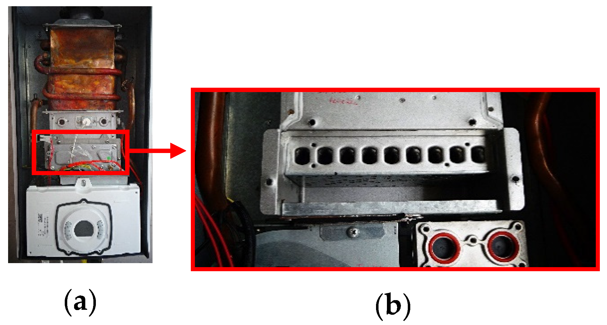
2.1. The Water Heater

In order to perform a comprehensive analysis of the water heater, it is necessary to prepare a test facility and the required instrumentation to retrieve all the necessary data. Figure 1 depicts the main structure of the test program. A test bench supports the water heater with the ancillary connections to the water mains and gas supply. A key component is the data acquisition system that monitors and links all the instrumentation to the data storage for subsequent analysis. The instrumentation includes a gas analyzer, manometers, flow meters, thermocouples, which enable the simultaneous, real time, measurement of the variables necessary to fully characterize the heater’s performance.
The water heater tested is a Sensor Compact model from Vulcano (Aveiro, Portugal) with 12 L/min (ref. WTD12AME31) with a variable output power between 2.9 and 20.8 kW. Based on the NP 4415:2002 standard [10] which classifies the type of combustion devices based on their possibility to exchange air and combustion gas with the surrounding area, once this water heater is totally sealed according the surround area, this device is classified as Type C. Examples of these devices can be found in apartments and small areas. Because the unit is sealed, all the combustion air is drawn from the outside of the apartment.
EN 437:2003 standard [11], defines the combustion devices based on the family fuel gases (3 families), which are also dependent in the Wobbe Index (Table 1) of the gas. The table also includes the High Heating Value (HHV), specific gravity (sg) and operating pressure (p).
For the water heater under study, the given classification is II2H3+, and defines that it can consume combustion gas from the 2nd and 3rd families, once the necessary settings are implemented before starting its operation (Table 2).
Table 3 summarizes the most important features of the water heater, which will be used to assess its performance in the course of the present work.

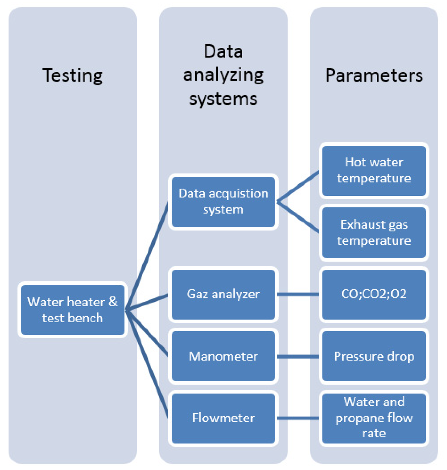
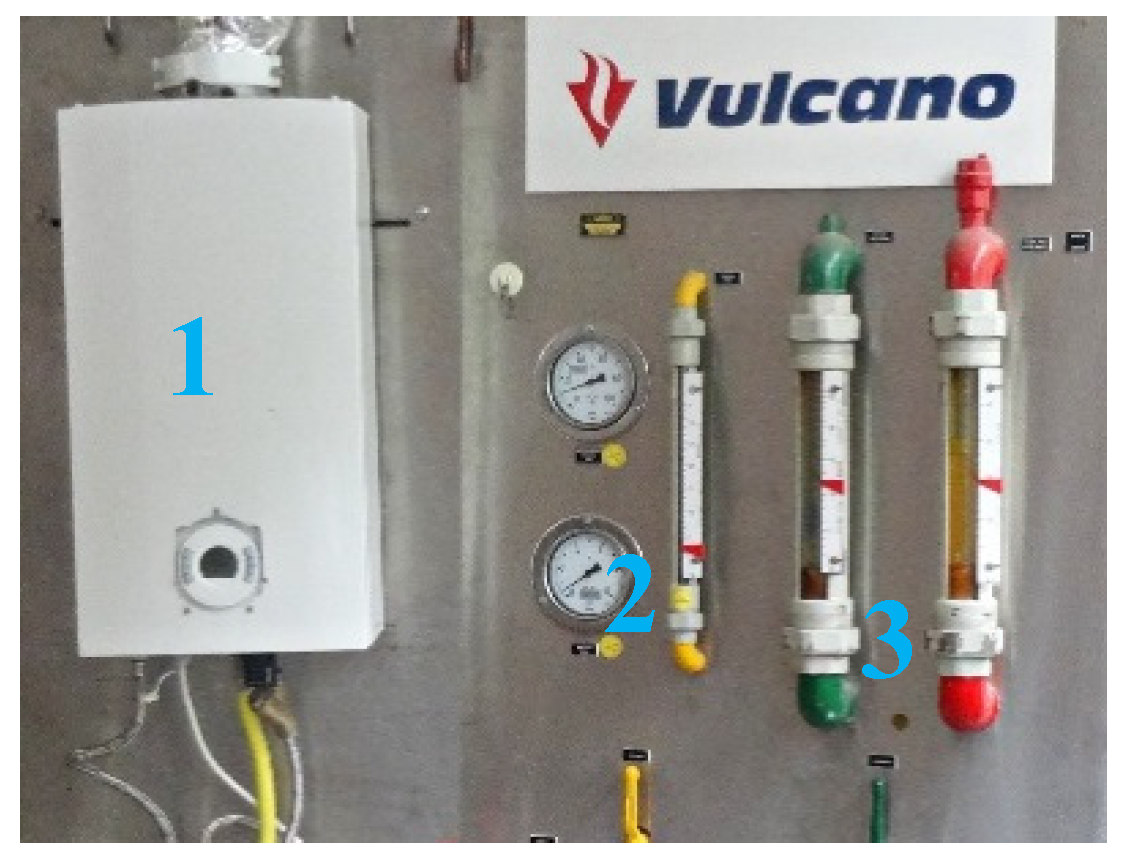
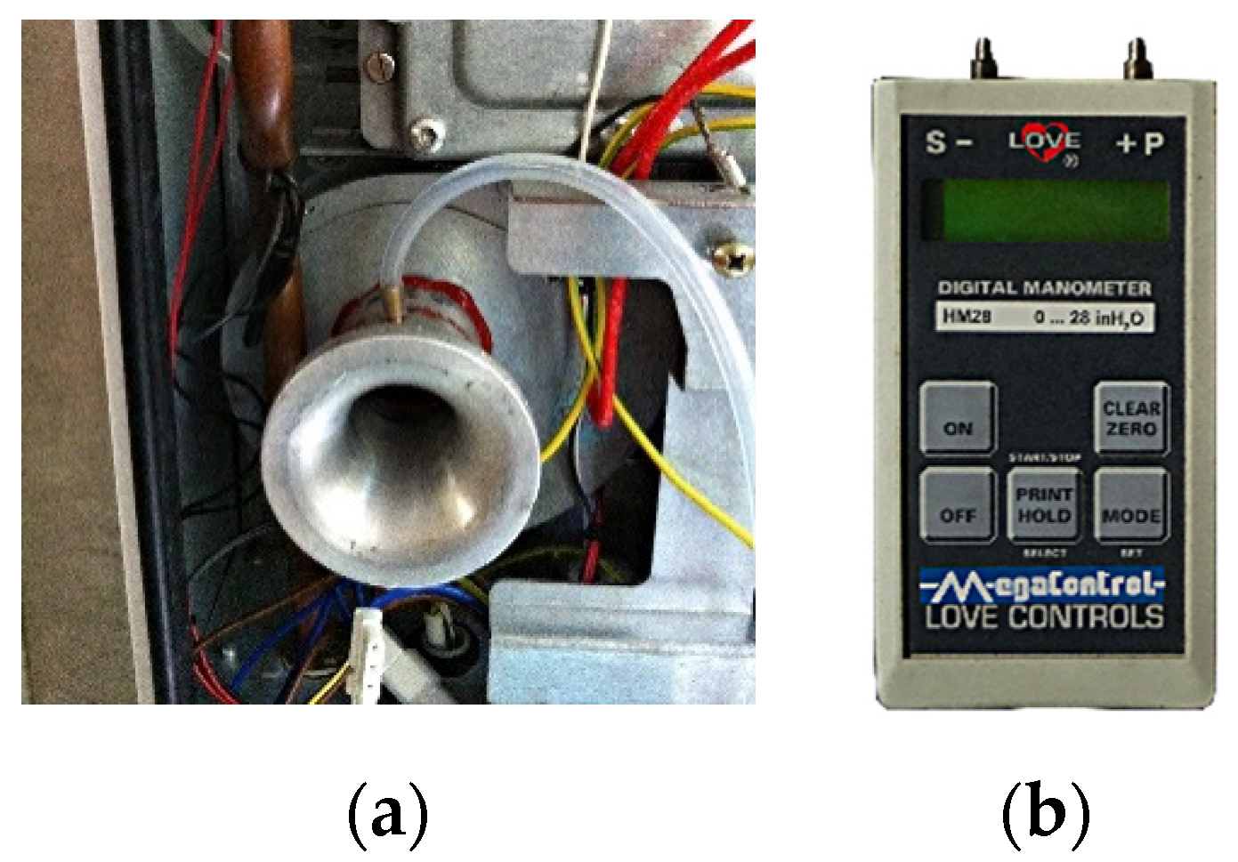
2.2. Experimental Facility

The tests were carried out on a test bench (provided by Vulcano, Aveiro, Portugal) which is made of pressure gauges for the water and gas fuel, control valves and rotameters to measure the water and gas flow rates (Figure 2). Their calibration was confirmed before the experimental program.
The fuel (propane) is supplied from two industrial size tanks (45 kg capacity each) that were connected in parallel to ensure the necessary vaporization of fuel even at low ambient temperatures. For these tests, the front cover of the water heater was removed to make it possible to place the bell mouth (for measuring the air flow) at the fan inlet and also to allow the routing of the sensor wiring (Figure 3).
Figure 4 details the fuel mixing plenum. Here, propane, delivered under pressure, is injected just upstream of the flute burner, and the jet entrains the surrounding air into the burner. However, the amount of air is throttled by the orifices, as shown by the restrictor plate, identified as “Primary air”. This gas mixture that goes inside the flute is stoichiometric rich (Ø > 1). The remaining air ends up going through the secondary circuit, through a holed surface (lower end of Figure 4) that gives direct access to the combustion chamber, completing the fuel burning.
As previously mentioned, the orifices limit the flow of primary air supplied to the gas fuel, balancing the distribution between primary and secondary air flow. It is this simple device that is the scope of this study, which aims to understand the influence of the dimensions of the restrictor’s orifices in the behavior of the water heater by analyzing the thermal performance and emission levels.
For this purpose, four parts identical to the original were produced, varying only the diameters of the intake holes, two of the parts with larger orifices (“+1 mm”, and “+0.5 mm”) and two other parts with smaller orifices (“−1 mm”, and “−0.5 mm”).
To analyze the flue gases a special probe was manufactured. This consists of a small diameter tube in a cross flow configuration with the flue gas stream. On the leading side of the tube, multiple orifices were drilled to sample the flue gases along a diameter of the cross section of the chimney, thus providing an average reading for their properties. This probe also contains a type K class 1 thermocouple for temperature acquisition. This probe was placed on the top of the chimney following Standard 26:2002 [12].
The flue gases were analyzed using a multi-gas analyzer from Signal Instruments (Willow Grove, PA, USA), model 9000 MGA. This unit (Figure 5) makes the independent analysis of exhaust gases for CO; CO2; O2. The gases are read after they pass through a circuit where the volatile particles and moisture are removed, obtaining clean samples for analysis. In the case of CO, the reading is done in ppm (parts per million) and in the case of CO2 and O2, the reading is presented in a volumetric percentage. The details of the arrangement for the sampling process are presented elsewhere [13].
Table 4 presents the main characteristics of the gas analyzer.
Two other type K class 1 thermocouples were added to the test facility in order to measure the water inlet and outlet temperature to calculate the thermal performance of the heater.
The signals from the temperature and the flue gases sensors were collected by a data acquisition board manufactured by NI - National Instruments (Austin, TX, USA). This consists of signal conditioning units, multiplexers, filters and an in-house developed software (on the labView platform) that enables the user to control all the parameters of data acquisition and storage. Table 5 details the main characteristics of the NI data acquisition board.

2.3. Experimental Techniques

The air flow was measured by a bell mouth attached to the inlet port of the ventilator. This entrance provides a smooth development of the ambient air flow into the ventilator with a negligible boundary layer. In this way, one may assume the flow inviscid and the Bernoulli equation can be used to estimate the velocity at the throat from the pressure drop Δ p , as described by Equation (1).
u t = 2 Δ p ρ
where ρ is the air density. Knowing the cross section area of the bell mouth at the throat, A t the volumetric flow rate Q ˙ is calculated by Equation (2). A discharge coefficient of 0.97 was introduced to compensate for friction losses. This was measured independently by comparing the flow rate assuming an inviscid flow with that obtained by integration of the velocity profile using a Laser Doppler Anemometry system.
Q ˙ = 0.97   u t A t
Figure 6a shows the bell mouth inlet port attached to the ventilator. The pressure drop is measured by a digital manometer (Figure 6b) whose calibration was verified with a Betz micro-manometer.
For measuring the air flow rate, a different approach was also used, based on the flow measurement of the gas exhaust and the fuel–air relationship. The molecular relationship to describe the propane combustion with air, can be expressed in Equation (3), [9,14]:
C x H y + ( x + y 4 ) ( 1 + e ) ( O 2 + 3.76 N 2 ) x CO 2 + y 2 H 2 O + ( x + y 4 )   e   O 2 + ( x + y 4 ) ( 1 + e )   3.76 N 2
where e is the excess air and this is assumed as a mixture of O2 and N2.
Simplifying Equation (3), the %O2 measured by the gas analyzer will give the air excess in the combustion (Equation (4)).
4.36 e = 1 % O 2 4.76
Finally, if the exhaust gas has an excess of air, it immediately leads that the values of combustion are above the stoichiometry relation (λ = 1). So, the air excess must be added to it (λ = 1 + e).
For the Air–Fuel Ratio (AFR) it is known that for a perfect burn of a propane molecule (C3H8), 5 molecules of air (O2 + N2) are necessary [14]. From this relationship and added to it the molar mass of both fluids, the AFR of this specific relationship is 15.6.
So, it is possible to calculate the flow of air using the excess of air in the exhaust gas (Equation (5)).
Q ˙ a i r = A F R   m ˙ f   λ ρ a i r
where m ˙ f is the mass flow of the fuel (kg/s).
To measure the exhaust gas, (namely CO; CO2; O2), a gas analyzer was necessary, as already mentioned. However, for the particular analysis of CO the data should be corrected in order to remove the excess air and water steam from the collected analysis of CO. For that, it is necessary to know what the maximum value of CO2 is that can result from the propane combustion (Table 6), and then relate the value with the CO and CO2 measured [12].
CO = ( CO ) M ( CO 2 ) N ( CO 2 ) M
( CO ) M and ( CO 2 ) M are the concentrations of carbon monoxide and carbon dioxide, in percentages; ( CO 2 ) N is the tabled value collected from Table 6.
Once CO is corrected, the values must be below 1000 ppm in order to be in compliance with the EN26:2002 [12] standard.
For an efficiency and emission analysis of the device some parameters were directly acquired, through the acquisition system, but others must be calculated. For this, the standard recommendations and best practices of the notified bodies were followed [9]. The energy efficiency of the devices is one of the important ones. This defines the relation between the given thermal power and the output power of a machine, in this case a water heater.
Based on the EN 26:2002 standard [12], which defines the minimum energy efficiency as 82% for a water heater above 10 kW; (Equation (7)).
η = P ˙ n Q ˙ t h
where P ˙ n and Q ˙ t h , are namely output and thermal power both in kW.
To perform the test according to the EN 26:2002 standard, the input water must have: (i) regulated flow; (ii) a pressure of 2 bar; (iii) a temperature below 25 -°C. The water heater must be capable to increase the water temperature by 40 ± 1 K. The calculation of output power must be given by Equation (8):
P ˙ n = m ˙ w   c p   Δ T w
where, m ˙ w , water mass flow (kg/s); c p , specific heat (J/(kgK)); and Δ T w the temperature variation of the water (input and output).
For the calculation of the thermal power the fuel gas conditions are used (Equation (9)):
Q ˙ t h = m ˙ f L H V
where LHV is the lower heating value of the fuel (kJ/kg).
Considering the information in the water heater technical book, the efficiency is between 91.5 and 94%, depending on whether it is at minimum or nominal power.

3. Results and Discussion

The results of this study are organized into four different topics:
  • Comparison between the experimental data and the reference data from the technical catalog (Vulcano);
  • comparison between the thermal performance and the flow of combustion gas with the different plates namely (“origin”; “−1 mm”; “−0.5 mm”; “+0.5 mm”; “+1 mm”);
  • influence of the nozzle on the water heater behavior;
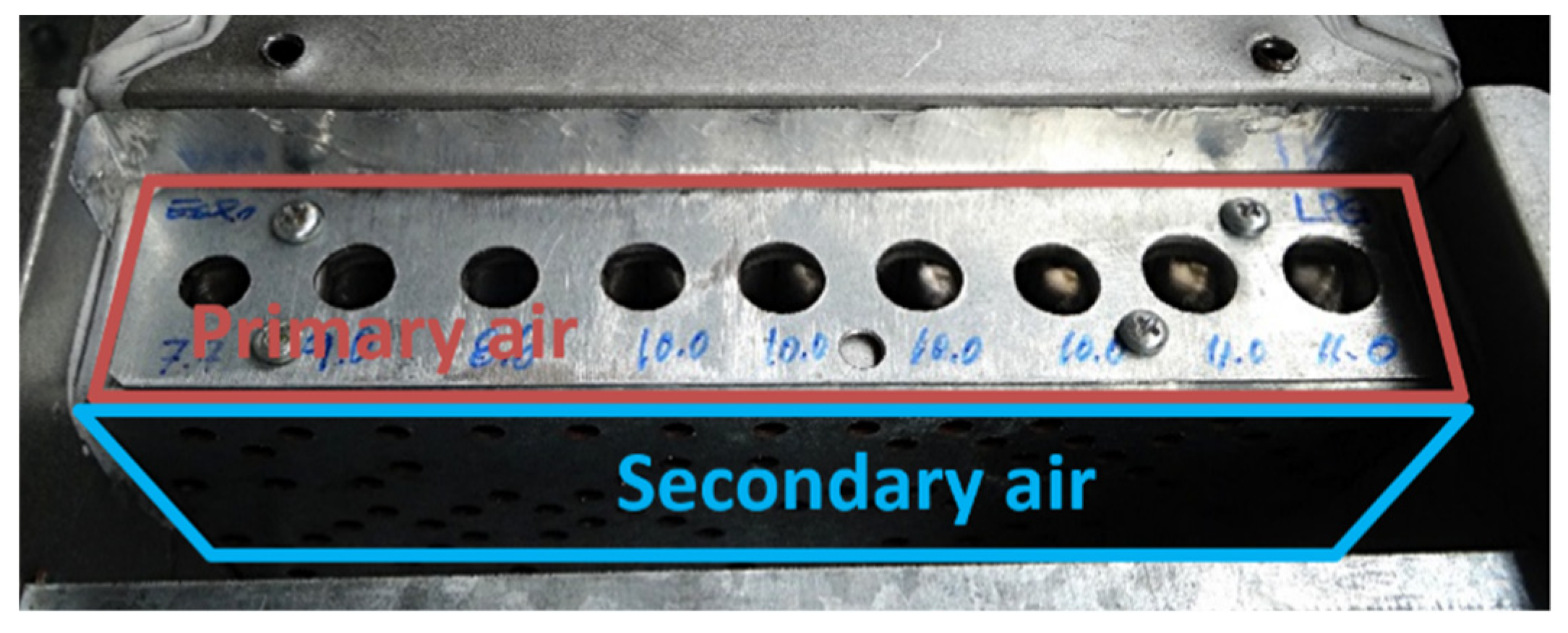
  • influence of the plates on the distribution of primary and secondary air.

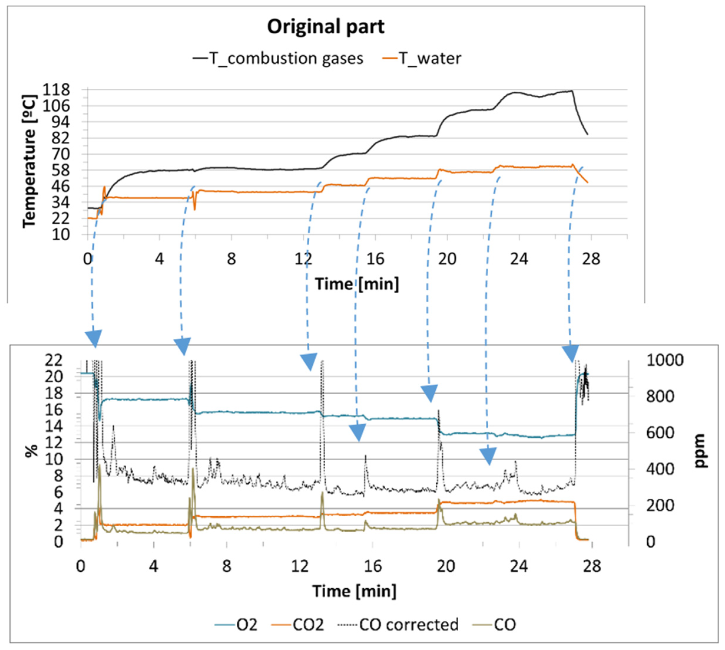
3.1. Operation in Standard Conditions

The set of experiments was designed to validate the experimental procedure with the reference conditions, as specified by the manufacturer. This will represent the default setup of the water heater, herein referred as the plate “origin”.
The experiments were carried out in a step-by-step manner, where the water set-up temperature (outlet) was varied from a minimum of 35 -°C to a maximum of 60 -°C, in 5 -°C steps.
The water inlet temperature was ±21 -°C, at a pressure of 1.5 bar, and the flow rate was set at 5.5 L/min. The control of propane flow was more difficult, as the supply was more unstable. The supply pressure was manually adjusted at the pressure regulator. During the experimental test, as the thermal power was increased, the pressure was adjusted upstream in order to obtain the required gas flow rate, monitored in the rotameter. Such transitions were accompanied by spikes in the emissions and temperatures (water and flue gases). Figure 7 depicts a profile of the test.
These effects are easily identified during the test (Figure 7), due to the sudden increase in combustion emissions, instability of the output water temperature or even on the instability of the flame (visually). It can be clearly observed that when the transitions occur, instabilities are observed. This behavior could be caused by a reduction in the gas supply pressure, leading to a drop in the gas discharge velocity at the nozzle and consequently an inefficient drag of primary air into the flute, creating an unbalanced air distribution and flame instability.
From the data recorded, a time average was applied to the values representing stable conditions for each one of the set points selected during the step-by-step profile. Table 7 presents the data regarding the efficiency, emissions and operating set-point.
One conclusion is that the actual operating conditions (as measured by the water outlet temperature) are very close to the setup settings. For a fixed heat transfer surface, the flue gases temperature increases with the power level. At a low power setting the flue gas will cause vapor condensation. Moreover, the excess air decreases with increasing power. Comparing the results with the limits defined by [12] (efficiency > 82%; corrected CO < 1000 ppm), it can be concluded that the water heater with the original setup is compliant with the standard. Table 8 summarizes the direct comparison between the experimental data and the reference (manufacturer’s) values.
Overall, the experimental data show a good agreement with the expected performance. The propane consumption is below the maximum claimed on the technical catalog (during the experimental trial the water flow was always kept at 5.5 L/min) and CO2 was also below that announced by Vulcano. The flow rate of combustion gases varied with the thermal load and, on average, was above the reference point (38.5 kg/h) by 7.4 kg/h. This situation is due to excess air during the burning of propane.

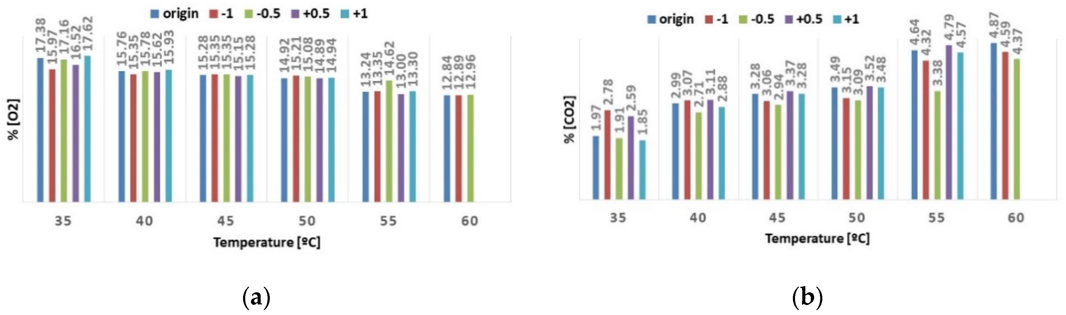
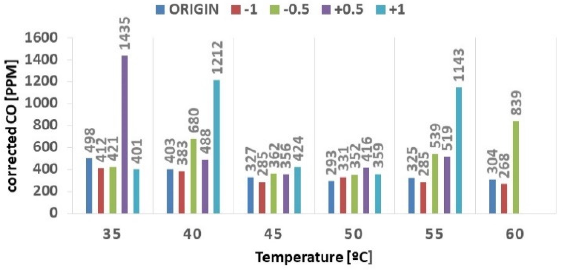
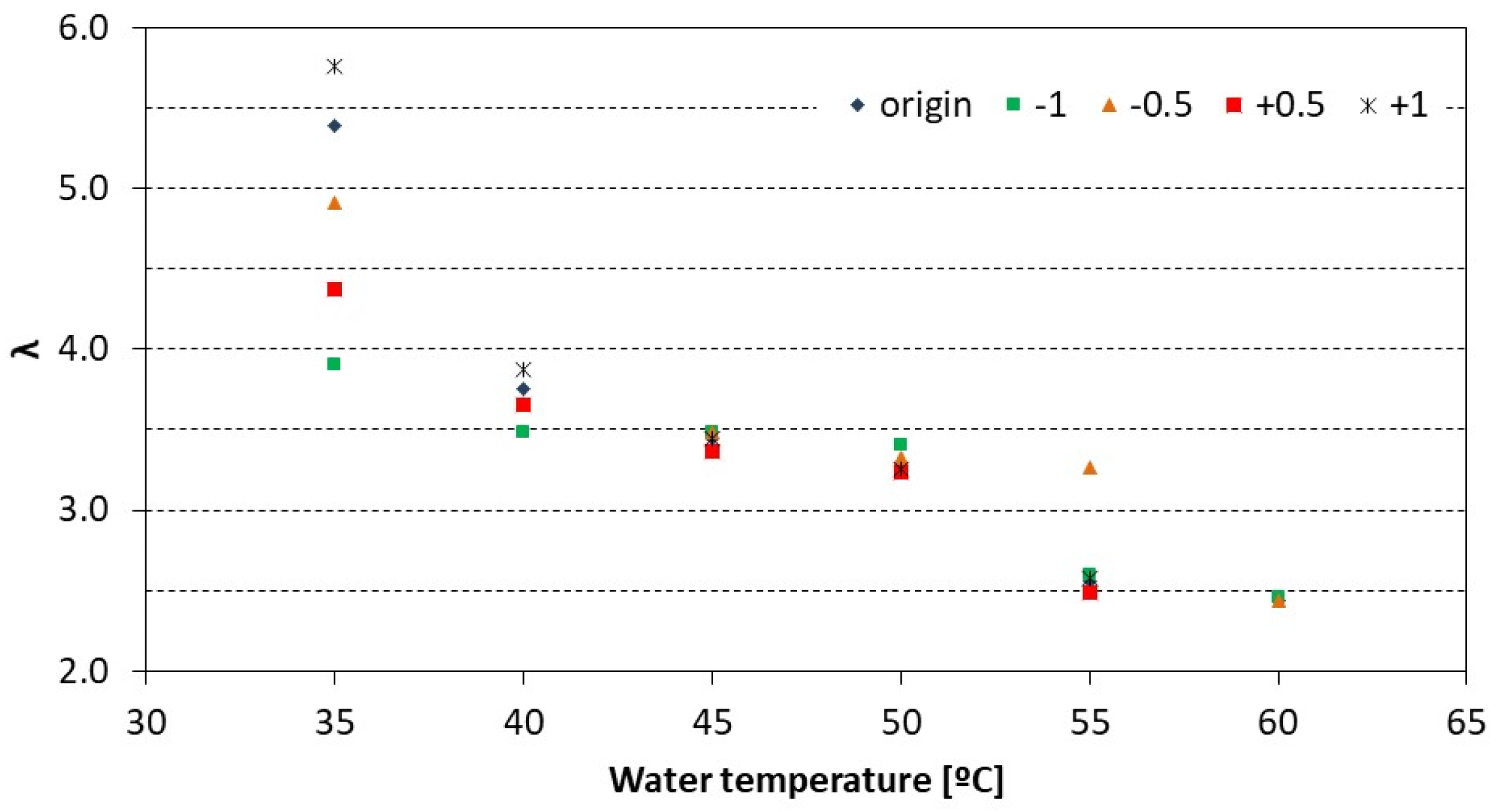
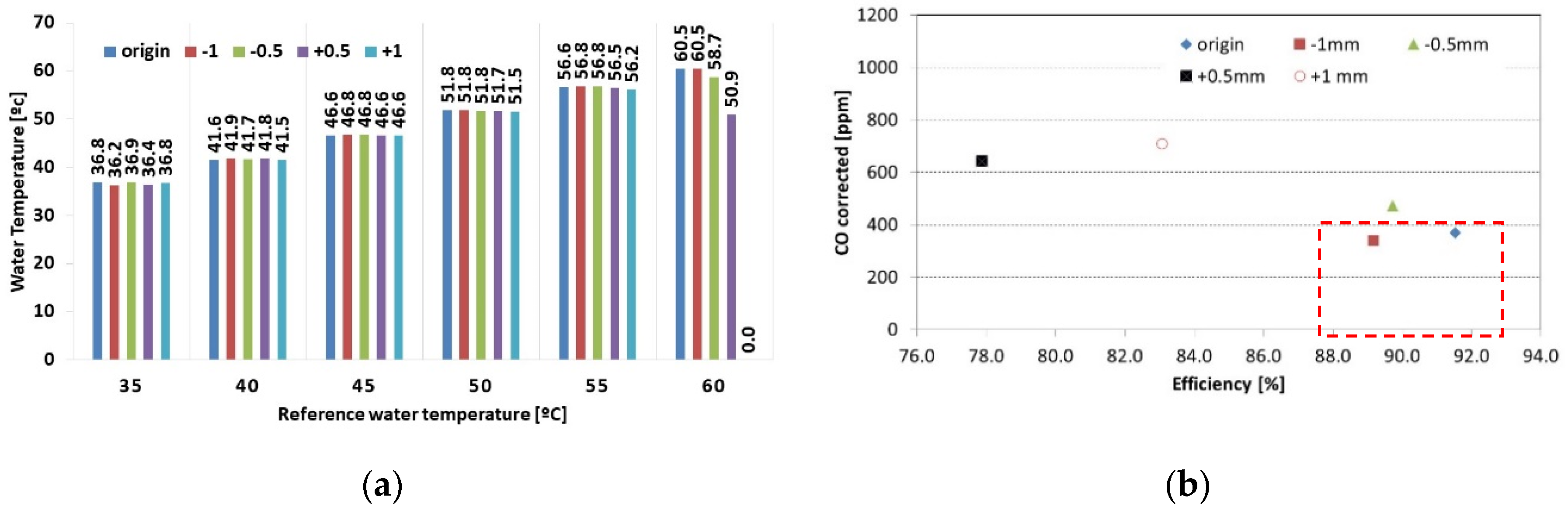
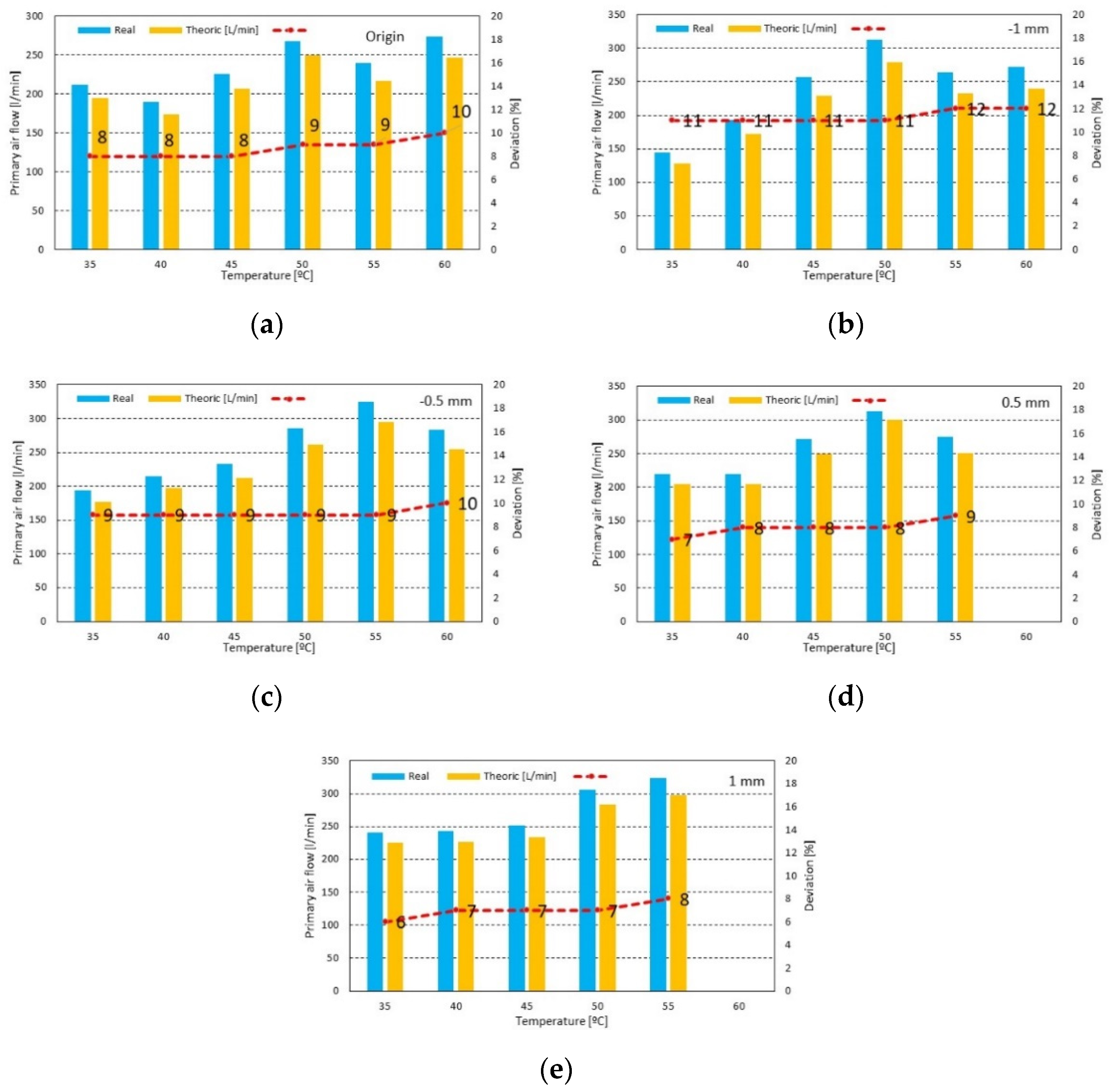
3.2. Influence of the Restrictor Plate

Figure 8 compares the influence of the diameter of the restrictor plate on the performance of the water heater. The data include all the restrictors tested in addition to the original configuration. The increase in the temperature set point shows a reduction in O2 concentration as the excess air decreases. As expected, the CO2 concentration increases as the O2 decreases. The excess air for all conditions was between 12 and 17%, and within the normal specifications for pre-mix combustion of fuel gas with an excess of air. There is no significant influence of the restrictor geometry.
For the plates with larger than standard orifice diameters (“+0.5 mm” and “+1 mm”), it was not possible to reach the maximum temperature of water (60 -°C), as shown in Figure 8 and Figure 9. The maximum water temperatures, for those orifices, were 56 °C and 55 °C, respectively.
By increasing the orifice diameters more air is entrained into the pre-mixing, reducing the air available for the secondary phase, which leads to incomplete combustion. As the fuel flow rate increases, this shift in the air split becomes more critical as the residence time is reduced (higher velocity of the flue gases). This trend is also identified by the increase in CO concentration (Figure 9), which can reach levels beyond the acceptable limits (1000 ppm). The increase in the orifice diameter (plates “+0.5 mm” and “+1 mm”), in general, worsens the combustion by reducing the amount of secondary air. For high fuel flow rates, this trend leads to incomplete combustion with expected increase in unburnt hydrocarbons. Furthermore, the flame tends to detach from the burner surface. On the other hand, the reduction of the plate orifice diameters—plates “−0.5 mm” and “−1 mm”— (with a reduction in the primary/secondary air split) appears to have negligible influence on the combustion efficiency. There is still enough primary air for flame ignition and the secondary air completes the fuel oxidation. The CO values were close to each other and all these plates were within the limits set by EN26:2002 [12]. Just analyzing the emission of corrected CO, the best results were achieved with the plate “−1 mm” which conclude that the smaller excess of air affects the formation of NO (Figure 9).
Figure 10 presents the influence of the plate orifice diameter on the excess air, λ. All the data follow the trend previously described with the ratio λ decreasing with the thermal load. Overall, there is no significant influence of the orifice geometry as the change in the pressure losses through the plate orifice is balanced by the flow through the secondary air flow route (Figure 4). For the lowest thermal load (water set point of 35 °C), there is a strong influence of the orifice diameter in the excess air. This may be due to either changes in the flow regime in the primary and/or secondary air routes or air entrainment by a low inertia fuel jet or a combination of both.
Figure 11a compares the actual outlet water temperature with the set point. It is observed that, although the water temperature is always regulated in excess, the control is accurate enough to yield water at the desired temperature. In addition, there is no influence of the orifice diameter on the operation of the water heater. Nonetheless, it is shown that for the highest thermal load, for the large orifice diameter, it becomes apparent that the useful heat decreases as the actual water temperature is lower than the set point. This observation is in agreement with the previous discussion on the CO formation. Figure 11b depicts the relationship between the CO concentration and the heater’s efficiency. The data show that the reduction in efficiency is related with the increase in CO and incomplete combustion (unburnt fuel). The tests with the various plates indicate that by reducing the amount of secondary air available (larger orifices) conditions for inefficient combustion are favored.
In Figure 11b, the data inside the dashed box identify the conditions that comply with the efficiency standards for water heaters. Both the standard plate and those with smaller diameters provide acceptable conditions.

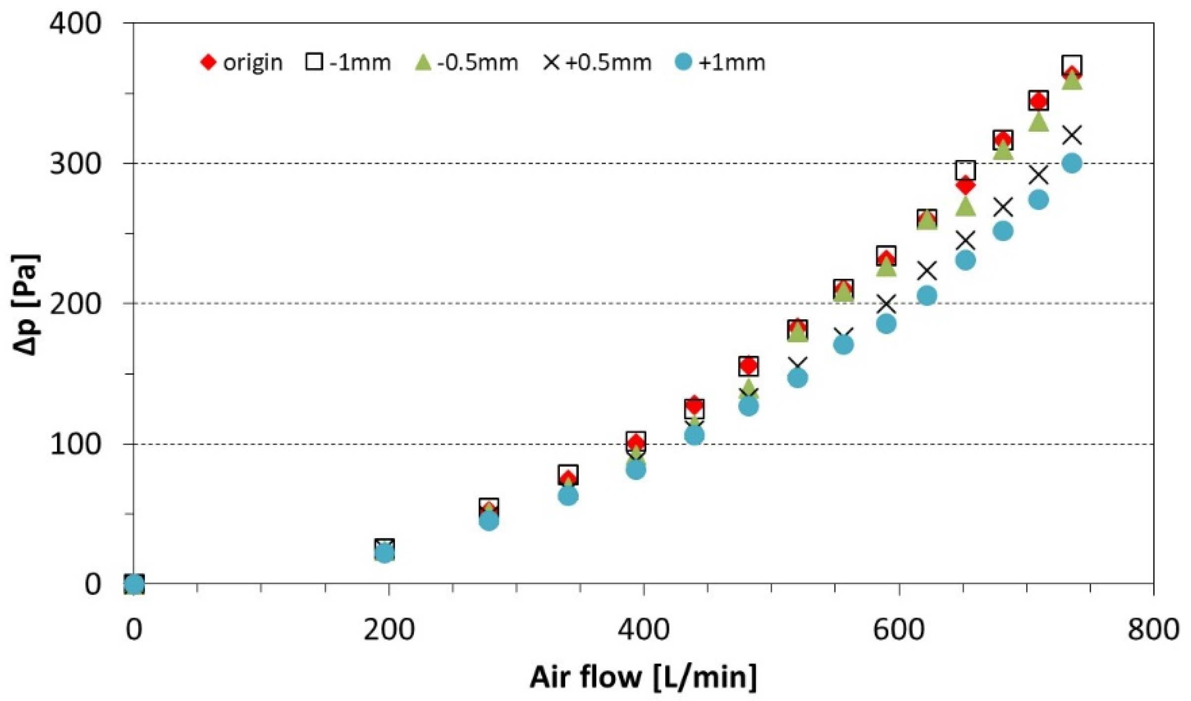
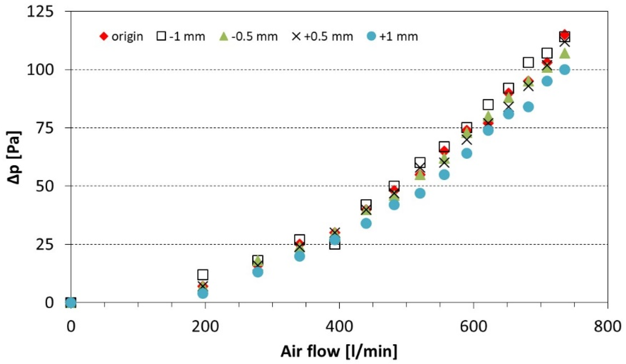
3.3. Influence of the Bell Mouth

As stated in Section 2.3, a 27 mm bell mouth was used at the inlet port of the ventilator to measure the air flow rate. This procedure was compared with the estimation of the total air flow from the Oxygen measurement in the flue gases. In addition, the influence of the bell mouth on the total air flow was investigated. The testes were carried out with the original restrictor plate for the same water temperatures referred to above.
The results are presented in Figure 12 where the excess air is also plotted. The data show that for the majority of the reference conditions the influence of the bell mouth is negligible when comparing the mass flow rates based on the flue gases composition. However, the data with the bell mouth appear to be consistently higher (by about 4%) than when the bell mouth is not present. This is due to the lower discharge coefficient presented by the smooth shaped bell mouth when compared with the blunt inlet of the ventilator, resulting in a lower pressure drop [15]. However, at the 35 °C setting, the behavior is reversed. It should be noted that in this situation, in the test of the water heater without the nozzle, the electronic board ordered the fan to work at a higher speed, which resulted in the highest air intake at 35 °C, compared to the same condition in the nozzle heater test. It can also be observed that the bell mouth gives results comparable with those from the gas analyzer with the bell mouth, which means that both measuring techniques are adequate.
In the end, it was decided to use the flow rate obtained by the O2 data from the gas analyzer in order to give a more consistent basis for all the operating conditions and to remove the influence (though negligible) of the bell mouth.

3.4. Influence of the Restrictor Plates on the Distribution of Primary and Secondary Air

Finally, an experimental test was developed to determine the primary/secondary air split in the heater. Pressure tapings were mounted in the air box upstream of the plate and downstream of the combustion chamber. The pressure drop for the various temperature settings when plotted against the flow rate, a discharge coefficient for the air path inside the burner could be obtained assuming a quadratic relationship. In addition, the same test was performed in “cold” conditions by bypassing the control unit of the burner, running the ventilator at the same flow rates and measuring the pressure drop. The results were very close.
Based on this similarity, another set of tests was carried out by alternatively blocking the primary and the secondary air ports and measuring the pressure drop. These tests were carried out also in “cold” conditions and enabled the determination of the discharge coefficients of the primary and secondary air paths. Again, for this purpose, the control unit was bypassed and the flow rate was varied, up to approximately 280 L/min.
Figure 13 depicts the influence of the various plates on the pressure drop across a wide range of flow rates. These data were obtained with the secondary air blocked, thus referring to the discharge coefficients of the primary air restrictor plates. It can be observed that the larger diameter orifices, as expected, present a lower pressure drop.
Figure 14 shows the same relationship but for the total air flow, removing all the blocking tape in both the primary and secondary air paths. The trend is similar though the actual pressure drop is approximately 75% lower than that in the primary air path for the same flow rate. Such a pressure drop distribution favors a higher ratio for the secondary air. In addition, the difference in pressure drop between the plate with large diameter orifice and that with the smaller diameter is much lower than that for the primary air supply. In fact, the secondary air flow is not affected by the restrictor plate.
From this, as shown in Table 9, the primary/secondary air split was calculated for all the plates tested. The data confirm the trend assumed previously that the increase in the orifice diameter of the plate shifts the air split towards higher ratios of the primary air, reducing the air available to complete the fuel oxidation. Although the data were obtained in “cold” conditions it should nevertheless be representative of the actual conditions observed in the burner.
Comparing the experimental results against the analytic measurements based on the dynamic balance method, Figure 15 shows that values of primary air measured are comparable with the values obtained via analytics. Of all the calculated situations, the maximum error obtained was 12%.

4. Conclusions

The present paper describes the experimental analysis of the influence of the diameter orifice of a restrictor plate on the primary air supply of a ventilated gas fuel water heater.
An experimental facility was built to measure the combustion gases’ flow rate and the emissions. Four new restrictors were manufactured in which the orifice diameter was slightly increased and decreased relative to the original.
The total air flow rate was measured both from the oxygen reading and from a pressure tapping on a bell mouth located at the inlet port of the ventilator. The results are within a 4% error.
The results show that this water heater operates at a very high excess air ratio. Moreover, when operating at high thermal loads, the excess air decreases as the O2 measurements indicate.
By increasing the orifice diameter of the restrictor plate there is a shift in the primary/secondary air supply towards a higher fraction of the primary air. This results in a flame detachment from the burner and incomplete combustion. This trend is confirmed by the increase in CO emissions and a reduction in the heater’s efficiency. In fact, in such conditions, the emission levels exceed the acceptable limit and the thermal efficiency is below the minimum required. Furthermore, for the highest thermal load, the highest temperature set up could not be achieved with the largest orifices as the combustion efficiency decreased substantially.
On the other hand, by decreasing the orifice diameter of the restrictor plate, there is no significant variation in performance when compared with the original design. In fact, the best results were obtained with orifices 1 mm smaller than the original design.
Tests were carried out to determine the discharge coefficients of the restrictors. From the data, a dynamic model was developed to calculate the primary air flow rate. The results are within a maximum 12% deviation from the experimental data.

Author Contributions

In the development of this paper the contribution of the authors was: conceptualization, J.T. and M.F.; methodology, R.M. and M.F.; software, S.T.; validation, S.T. and R.M.; formal analysis, R.M.; investigation, R.M.; resources, J.T.; data curation, R.M.; writing—original draft preparation, R.M.; writing—review and editing, S.T. and J.T.; supervision, J.T. and M.F.; project administration, J.T.; funding acquisition, J.T. All authors have read and agreed to the published version of the manuscript.

Funding

This work has been supported by FCT—Fundação para a Ciência e Tecnologia within the R&D Units Project Scope: UIDB/00319/2020 (ALGORITMI Center) and UIDB/00319/2020 (METRICS Center).

Acknowledgments

The authors acknowledge the company Vulcano—Bosch Thermotechnology, SA, who provided the test bench and the water heater.

Conflicts of Interest

The authors have no conflict of interest.

References

  1. Ibrahim, O.; Fardoun, F.; Louahlia-Gualous, H. Review of Water-Heating Systems: General Selection Approach Based on Energy and Environmental Aspects. Build. Environ. 2014, 72, 259–286. [Google Scholar] [CrossRef]
  2. Hohne, P.A.; Kusakana, K.; Numbi, B.P. A Review of Water Heating Technologies: An Application to the South African Context. Energy Rep. 2019, 5, 1–19. [Google Scholar] [CrossRef]
  3. U.S. Department of Energy. Water Heater Market Profile 2009; ENERGY STAR: Washington, DC, USA, 2009; p. 20.
  4. Ma, X.; Zhang, H.; You, S.; Zheng, X.; Miao, Q.; Li, H. Numerical Investigations on Combustion Characteristics, NO and CO Emission of Gas Instantaneous Water Heater with Partial Premixed Combustion. Energy Procedia 2019, 158, 1372–1379. [Google Scholar] [CrossRef]
  5. Johnson, G.; Beausoleil-Morrison, I. The Calibration and Validation of a Model for Predicting the Performance of Gas-fired Tankless Water Heaters in Domestic Hot Water Applications. Appl. Energy 2016, 177, 740–750. [Google Scholar] [CrossRef]
  6. Li, G. Parallel Loop Configuration for Hybrid Heat Pump—Gas Fired Water Heater System with Smart Control Strategy. Appl. Therm. Eng. 2018, 138, 801–807. [Google Scholar] [CrossRef]
  7. Choudhury, S.; McDonell, V.G.; Samuelsen, S. Combustion Performance of low-NOx and Conventional Storage Water Heaters Pperated on Hydrogen Enriched Natural Gas. Int. J. Hydrog. Energy 2020, 45, 2405–2417. [Google Scholar] [CrossRef]
  8. Czerski, G.; Gebhardt, Z.; Strugala, A.; Butrymowicz, C. Gas-fired Instantaneous Water Heaters with Combustion Chamber Sealed with Respect to the Room in Multi-Storey Residential Buildings—Results of Pilot Plants Tests. Energy Build. 2013, 57, 237–244. [Google Scholar] [CrossRef]
  9. De Paepe, M.; T’Joen, C.; Huisseune, H.; van Belleghem, M.; Kessen, V. Comparison of Different Testing Methods for Gas Fired Domestic Boiler Efficiency Determination. Appl. Therm. Eng. 2013, 50, 275–281. [Google Scholar] [CrossRef]
  10. NP 1037-1_2002; Ventilação e Evacuação dos Produtos da Combustão dos Locais com Aparelhos a Gás. IPQ: Lisbon, Portugal, 2002.
  11. EN 437:2003 E; Test Gases—Test Pressures—Appliance Categories. IPQ: Lisbon, Portugal, 2003; p. 39.
  12. EN 26:2002; Gas-Fired Instantaneous Water Heaters for the Production of Domestic Hot Water. IPQ: Lisbon, Portugal, 2002.
  13. Silva, J.P.V.; Fraga, L.G.; Ferreira, M.E.C.; Chapela, S.; Porteiro, J.; Teixeira, S.F.C.; Teixeira, J.C.F. Combustion Modelling of a 20 kW Pellet Boiler. In Energy: Volume 6B; ASME, Ed.; ASME: New York, NY, USA, 2018; p. V06BT08A036. [Google Scholar] [CrossRef]
  14. El-Mahallawy, F.; El-Din Habik, S. Fundamental and Technology of Combustion; Elsevier Science Ltd., Digital Version 2002. Available online: https://www.sciencedirect.com/book/9780080441061/fundamentals-and-technology-of-combustion (accessed on 1 February 2020).
  15. Persoons, T.; Vanierschot, M.; Van den Bulck, E. Oblique inlet pressure loss for swirling flow entering a catalyst substrate. Exp. Therm. Fluid Sci. 2008, 32, 1222–1231. [Google Scholar] [CrossRef]
Figure 1. Overview of the test conditions.
Proceedings 58 00017 g001
Figure 2. Water heater from Vulcano and gas and water flowmeters: 1- Water heater; 2- gas flowmeter; 3- water flowmeter.
Proceedings 58 00017 g002
Figure 3. Water heater: (a) without front cap; (b) location of air–fuel mixing plenum.
Proceedings 58 00017 g003
Figure 4. Primary and secondary air.
Proceedings 58 00017 g004
Figure 5. Primary and Secondary air.
Proceedings 58 00017 g005
Figure 6. (a) Nozzle to acquire the static pressure; (b) digital manometer Love Controls (max. 7000 Pa).
Proceedings 58 00017 g006
Figure 7. Water heater behavior along the test and identification of the CO increase.
Proceedings 58 00017 g007
Figure 8. (a) O2 results for all test conditions; (b) CO2 results for all test conditions.
Proceedings 58 00017 g008
Figure 9. Corrected CO (without air and water steam) for all test conditions. Graphic with a highlighted limit of 1000 ppm [12].
Proceedings 58 00017 g009
Figure 10. Excess air for all test conditions.
Proceedings 58 00017 g010
Figure 11. (a) Water temperature; (b) relation of CO corrected and water heater yield (EN 26:2000).
Proceedings 58 00017 g011
Figure 12. Air flow rate and excess air for the water heater w/ and wt/the nozzle.
Proceedings 58 00017 g012
Figure 13. Primary Air; influence of the orifice diameter on the pressure drop.
Proceedings 58 00017 g013
Figure 14. Influence of the orifice diameter on the pressure drop for total air flow.
Proceedings 58 00017 g014
Figure 15. Comparison between the primary air flow rate (measured vs. theoretical) as a function of the water temperature. (a)–(e) concerns a specific orifice diameter, as referred on the top.
Proceedings 58 00017 g015
Table 1. Family of combustion gas (EN437:2003) [2].
FamilyGas HHV (MJ/m3) sg (Air = 1) Wobbe (MJ/m3) p (mbar)
1stCity gas
Methane air
17.6
20.9
0.58
0.82
23.1
23.1
8
8
2ndNatural gas
Propane air
41.9
56.7
0.65
1.31
52.1
50.5
20
20
3rdPropane
Butane
100.5
125.6
1.6
2
79.5
87.9
37
30
Table 2. Necessary settings based on the combustion gas family.
FuelMin. Pressure Supply (mbar)Consumption of Propane Gas (m3/h)
Nat. gas G23 20 2.4
Butane G30 28–30 0.705
Propane G31 37 0.890
Table 3. Characteristics of the water heater (WTD12).
VariableMinimumMaximum
Thermal power (kW) 3.022.5
Output power (kW)2.920.5
Water flow (L/min)2.212
Exhaust gas temperature (-°C)50170
Propane consumption (kg/h)1.7
CO2 (%)6.6
Combustion gas flow (kg/h)38.5
Table 4. Analyzer gas features.
Analyzed GasCOCO2O2
Scale 1000, 5000, 10,000 ppm5, 10, 20%5, 10, 25%
Response time <15 s<15 s5 s
Linearity <0.5% of the range
Zero offset and span<0.1% of the range, in 1 h, at constant temperature and pressure
Exits 0–10 V; 4–20 mA; RS232
Table 5. Data acquisition system from NI (Chassi model SCXI-1000).
Acquisition Plate SCXI-1300Signal Module SCXI-1102
ThermocouplesAccuracy of 1.3 -°C
Repeatability of 0.5 -°C
2 Hz low pass filter
32 channels
Acquisition plate SCXI-1303Signal module SCXI-1180
Gas analyzerAccuracy of 1.3 -°C
Repeatability of 0.5 -°C
2 Hz low pass filter
Table 6. Percentage of CO2 based on the type of gas (EN 26:2002).
Gas NameG25; G231 G26 G30 G31; G130
(𝐶𝑂2)𝑁 1155 11.9 14.0 13.7
Gas nameG120G140 G141 G150
(𝐶𝑂2)𝑁8.35 7.8 7.9 11.8
Table 7. Combustion gas and energy behavior for the water heater with the original setup.
Combustion gasT. Selected. (ºC)354045505560
O2 (%) 17.3815.7615.2814.9213.2412.84
CO2 (%) 1.972.993.283.494.644.87
CO (ppm) 64797773108106
Corrected CO (ppm) 498403327293325304
Flow combustion gas (kg/s) 0.01140.01020.01220.01480.01300.0149
Excess air coeff. λ 5.393.753.443.242.56 2.44
Energy behaviorT. hot water (ºC) 374247525760
T. exhaust gas (ºC) 53596881100114
Propane flow (kg/s) 0.000130.000170.000220.000290.000320.00038
Air flow (m3/s) 0.00920.00820.00980.01190.01040.0119
Power output (kW) 5.747.589.5411.5313.4014.89
Power thermal (kW) 6.207.9710.3313.2814.7517.70
Efficiency (%) 92.795.292.486.990.884.1
Table 8. Comparison between the experimental data and technical features from Vulcano (Aveiro, Portugal).
CatalogExperimental
Propane consumption (kg/h)1.7Max 1.4
CO2 (%)6.6Max 4.8
Flow of flue gases (kg/h)38.5Aver. 45.9
Table 9. Percentage of primary and secondary air by the influence of the orifice diameter.
Air splitOrigin−1 mm−0.5 mm+0.5 mm+1 mm
Primary air [%] 38.337.839.141.242.8
Secondary air [%] 61.762.260.958.857.2
Publisher’s Note: MDPI stays neutral with regard to jurisdictional claims in published maps and institutional affiliations.

