1. Introduction
In recent years, wire systems of supplying drones have become more and more popular. Such constructions are often used for analyzing the air quality or surveillance systems [
1]. The basic difference, in comparison to classical battery solutions, is the fact that with this system the drone is supplied with the use of an electrical wire connected to the Ground Power Unit GPU [
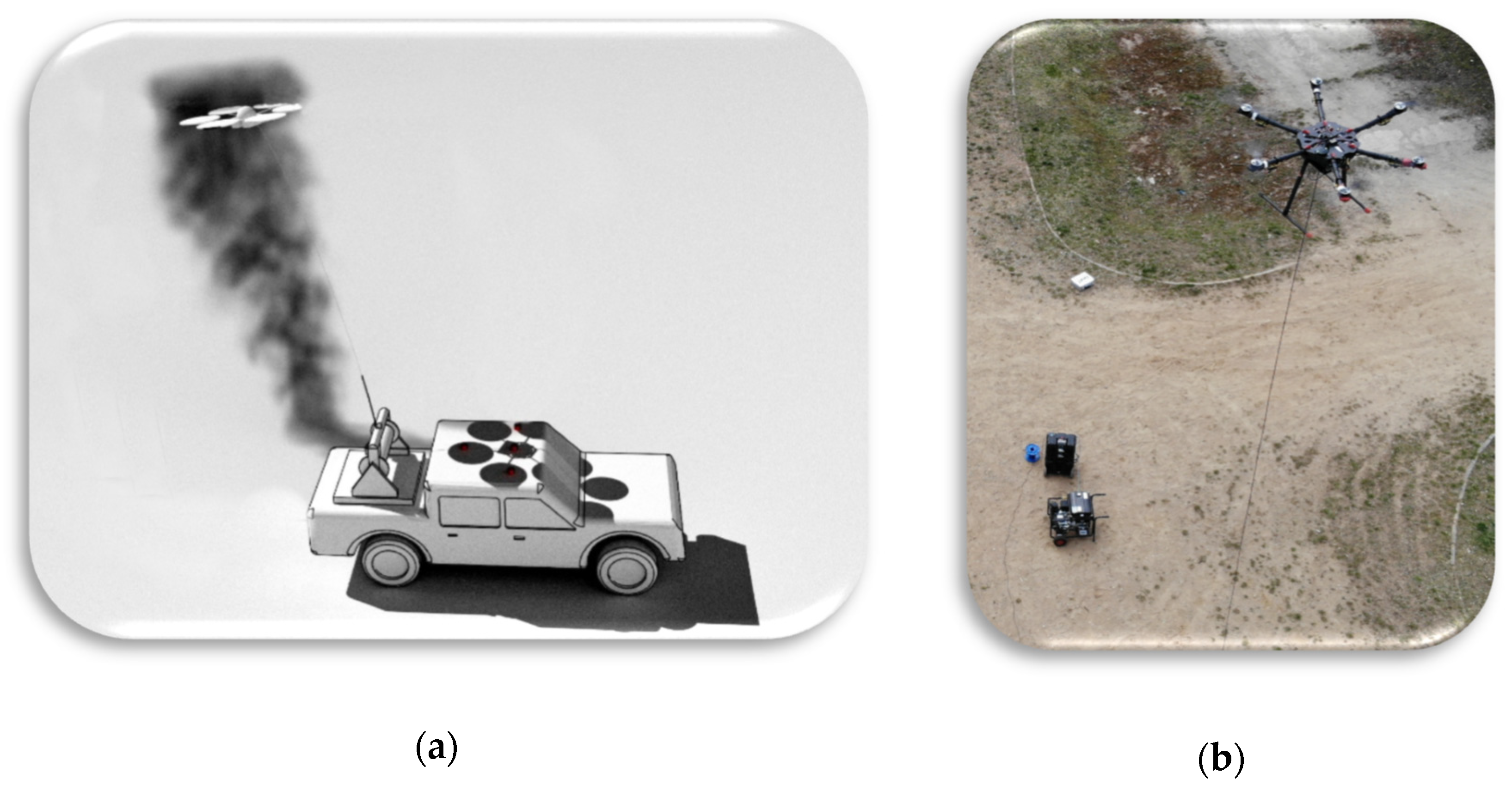
2]. Such a construction may be placed directly on the ground or on the board of a transport vehicle, which will then become the central unit. In such a case, to supply the drone from the ground station, the systems of AC/DC (placed on the ground) and DC/DC converters (on board of the drone) are applied in the supply path of the flying system [
3]. Then, electrical power is transmitted to the drone, and the distribution and management of the power consumed by the local devices placed on board the drone are executed (
Figure 1).
This last stage of the tests is completed through applying proper DC/DC converters which lowers the voltage. This aims at adjusting the voltage levels to the proper power values of the drone onboard devices. Due to this solution, it is possible to limit the power loss caused by the current flow within the supplying wire as well as a significant decrease of its required diameter and, therefore, its mass.
2. Basic Blocks of the Modular Power Supply System
As mentioned in the introduction, this paper relates to the issue of empowering a multirotor flying platform from a ground station. The main cause of building the system was the need to reduce the flight time limitation resulting from the capacity of the batteries. For this purpose, a system of empowering the device from a ground station was invented, which would theoretically allow to endure the time of flying endlessly. The basic blocks of the system, regardless of the variant, are a ground power system, an electrical energy storage device, a power cable winder and a converter lowering the supplying voltage to the level required by the BLDC controllers. During the works upon the project, various variants of the power supply construction, regarding such criteria as reliability, dimensions, efficiency, mobility and the price of the analyzed solution, were taken into account.
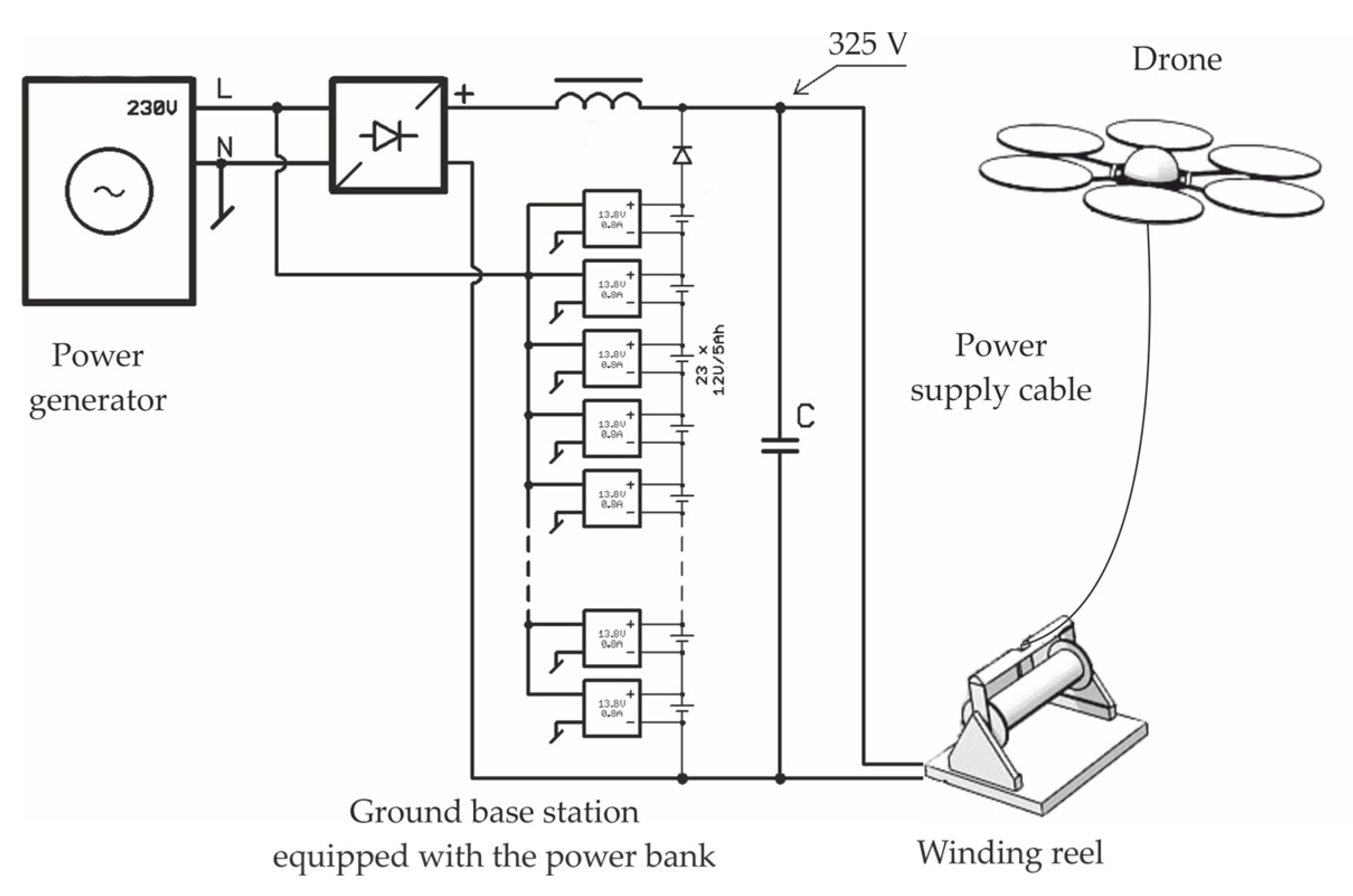
Regarding all the above factors, one of the analyzed examples is presented in
Figure 2. In this solution, the system is powered from a combustion electric power generator of the power of 6 kW and the output voltage of 230 V. The voltage is rectified and filtered by a LC filter (the procedure of selecting parameters will be presented in the extended version of the paper). The rectified and filtered voltage of the value of about 325 V is transmitted on the winder and further, through a wire, to the flying unit. Processing the power voltage by the drone itself will be described below. The power of 325 V was chosen because of high accessibility, the limitation of the wire diameter and satisfactory parameters of the semi-conductive elements of the converters lowering the voltage to the power level of the BLDC controllers of the flying unit.
It seems obvious that in case of power loss from the ground station, without an energy storage system, the flying unit will suffer a serious damage. Owing to this fact, it was decided to employ two power sources: one of small capacity (and, therefore, small weight and size), placed in the drone, and another one, seated on the ground, which has bigger capacity and can supply the flight with an average payload of 5 kg for about 45 min. The ground base station was connected parallelly to the output of the power generator. The ground power unit performance is fully autonomous and the reaction time is immediate.
3. Selected Topologies of the Onboard Supply System
This paper contains three proposed topologies of the drone onboard power system: a two-stage power system with distributed power supply, a two-stage power system of distributed supply with cooperation of systems supplying opposite arms of the drone, and a single-stage power system with transformer isolation.
A two-stage power system consists of a single central converter—Master as well as Slave buck converters that independently supply each drone engine. The central converter is a 3-phase interleaved buck converter which stepping down the drone supply voltage from 325 V to the level of 100 V. In the second stage of energy conversion, the Slave converters stepping down the voltage from 100 to 25 V. Such a topology allows operation with a greater duty cycle than in the case of a single step-down topology. Moreover, damaging a single converter or engine will not distort the performance of the other components of the system. In the case of such a failure, the avionics should allow a safe landing, which will minimize the damage of the flying unit.
The two-stage power system with load balancing, similarly as in the previous case, consists of a central Master converter as well as Slave converters stepping down the voltage from 100 to 25 V, used to supply each drone engine independently. Additionally, in this topology, the Slave converters empowering the opposite arms of the drone are connected parallelly through diodes. This solution exhibits all advantages of the previously discussed one and additively, in the case when one converter is overloaded, the other one will parallelly support its work. The diodes will provide proper operating for the load lower than rated.
The single-stage power system consists of a SiC full-bridge inverter, a step-down transformer as well as Schottky rectifier diodes at the secondary side of the transformer. This is the simplest solution that is characterized with the possibility of working at high transient overloads. However, in the case of damaging of a single semiconductor, the engines lose power in this topology.
4. Results and Conclusions
As a result of the research, three topologies of power systems of a tethered drone were worked out. All the devices were tested in laboratory conditions and their functional properties were compared. The research results show that the two-stage power system with load balancing provides safer flights, which results from the fact that the central Master converter is less loaded. Whereas, the single-stage power system is simple and immune to temporary power changes. However, it appears to have the greatest mass of all proposed solutions.
Author Contributions
W.W. Research coordination, W.W., P.F. and K.K. Investigation, P.F. and K.K. Device realization, W.W., P.F. and K.K. Article writing, W.W. Writing review and editing, W.W. and P.F. Data analysis, visualization, W.W. Funding Acquisition. All authors have read and agreed to the published version of the manuscript.
Acknowledgments
The research was supported by R&D project POIR.01.02.00-00-0072/16 titled Modular surveying-inspecting system based on a flying multirotor platform powered from a ground station financed by Polish National Center for Research and Development and was carried out as part of the work WZ/WE-IA/2/2020 of the Bialystok University of Technology and financed from a subsidy provided by the Minister of Science and Higher Education.
Conflicts of Interest
The authors declare no conflict of interest.
References
- Montanya, J.; Lopez, J.A.; Fontanes, P.; Urbani, M.; van der Velde, O.; Romero, D. Using tethered drones to investigate ESD in wind turbine blades during fair and thunderstorm weather. In Proceedings of the 34th International Conference on Lightning Protection, ICLP, Rzeszow, Poland, 2–7 September 2018; Institute of Electrical and Electronics Engineers Inc.: Piscataway, NJ, USA, 2018. [Google Scholar]
- Boukoberine, M.N.; Zhou, Z.; Benbouzid, M. Power Supply Architectures for Drones—A Review; Institute of Electrical and Electronics Engineers (IEEE): Piscataway, NJ, USA, 2019; pp. 5826–5831. [Google Scholar]
- Xu, Z.W.; Zhang, Z.; Li, H.; He, M.X.; Tang, J.C.; Xu, K.; Ren, X.; Chen, Q. 1-kV input 300-kHz SiC LLC converters with matrix transformers. In Proceedings of the Conference Proceedings—IEEE Applied Power Electronics Conference and Exposition—APEC; Institute of Electrical and Electronics Engineers Inc: Anaheim, CA, USA, 2019; pp. 2337–2343.
| Publisher’s Note: MDPI stays neutral with regard to jurisdictional claims in published maps and institutional affiliations. |
© 2020 by the authors. Licensee MDPI, Basel, Switzerland. This article is an open access article distributed under the terms and conditions of the Creative Commons Attribution (CC BY) license (https://creativecommons.org/licenses/by/4.0/).


