Abstract
The swimming turn is one of the important factors in producing results in a race. Knowing the mechanical quantities in turns is useful to quantify the turning technique. However, experimental measurements often require considerable time and costs. The aim of this study was to construct a simulation model of a flip turn in the crawl stroke by extending the swimming human simulation model SWUM. The joint motion was created based on the standard crawl motion and a turn commentary video on the Internet. Furthermore, the contact with the wall was represented as forces by virtual springs and dampers and the frictional forces. As a result of simulation, a successful turning motion was confirmed. It was also found that the simulated contact time, the maximum force, and the impulse were within the ranges of the previous research.
1. Introduction
In a race of competitive swimming, turn time can be more than 1/3 of the whole race. It was also pointed out that there is a strong positive correlation between the turn time and record [1,2]. Therefore, improvement of turning technique is important to enhance performance for a competitive swimmer. To quantify the turning technique, it is useful to know the mechanical quantities in turns, such as time on wall and impulse. Several experimental studies were conducted to measure these quantities [3,4]. However, experimental measurements often require considerable time and costs. Therefore, the purpose of this study was to construct a simulation model of flip turn in the crawl stroke by extending the swimming human simulation model SWUM [5,6].
2. Methods
2.1. SWUM
The simulation model of flip turn was constructed by extending the swimming human body simulation model SWUM [5]. SWUM was designed to solve the six degrees-of-freedom absolute movement of the whole swimmer’s body as a single rigid body by time integration using the inputs of the swimmer’s body geometry and relative joint motion. The swimming speed, roll, pitch and yaw motions, propulsive efficiency, joint torques, and so on are computed as the output data. The swimmer’s body is represented by 21 rigid body as follows: lower waist, upper waist, lower chest, upper chest, shoulders, neck, head, upper hip, lower hip, thighs (right and left), shanks (right and left), feet (right and left), upper arms (right and left), forearms (right and left), and hands (right and left). Each body segment is represented by a truncated elliptic cone. In this research, these shape and positional relationship are based on the average shape of Japanese men in their twenties [7]. The unsteady fluid force and gravitational force are taken into account as external forces acting on the whole body. The unsteady fluid force is assumed to be the sum of the inertial force due to the added mass of the fluid, normal and tangential drag forces, and buoyancy.
2.2. Joint Motion
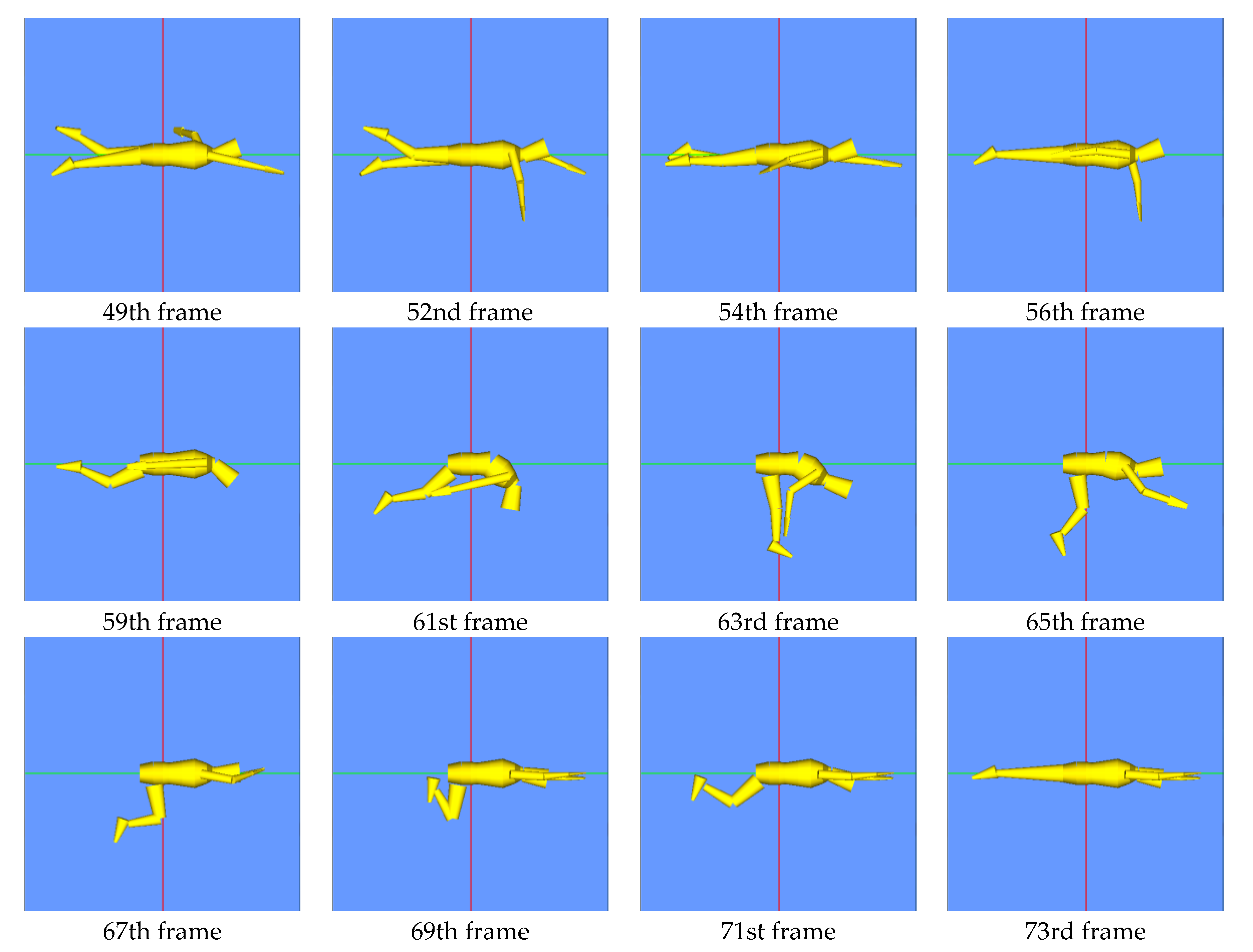
Swimmer’s joint motion was created based on the standard crawl motion made in previous research [8] and a turn commentary video on the Internet [9]. In the created joint motion, the swimmer was supposed to perform three cycles of the crawl stroke first, then perform flip turn. One stroke cycle of the crawl was 1.96 s and was divided into 18 frames. In other words, the three crawl strokes were represented by 54 frames and the time per frame was 0.109 s. The time of the turn in the video was 8.6 s. This time was divided into 46 frames with the same time per frame as the crawl stroke part. For each time frame, the joint angles were determined using the still images, which were converted from the video. An operator compared the body positions in the images with those in simulation model on the computer screen, and adjusted the joint angles in the model so that both positions became consistent with each other. As a result, the joint motion consisted of 100 frames and the total time was 10.8 s. The created joint motion including flip turn is shown in Figure 1. The joint angles between time frames were automatically interpolated using the Spline function.
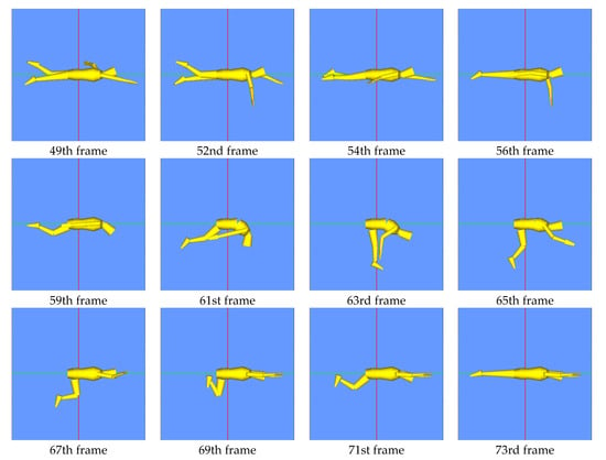
Figure 1.
The created joint motion including flip turn.
2.3. Contact with the Wall
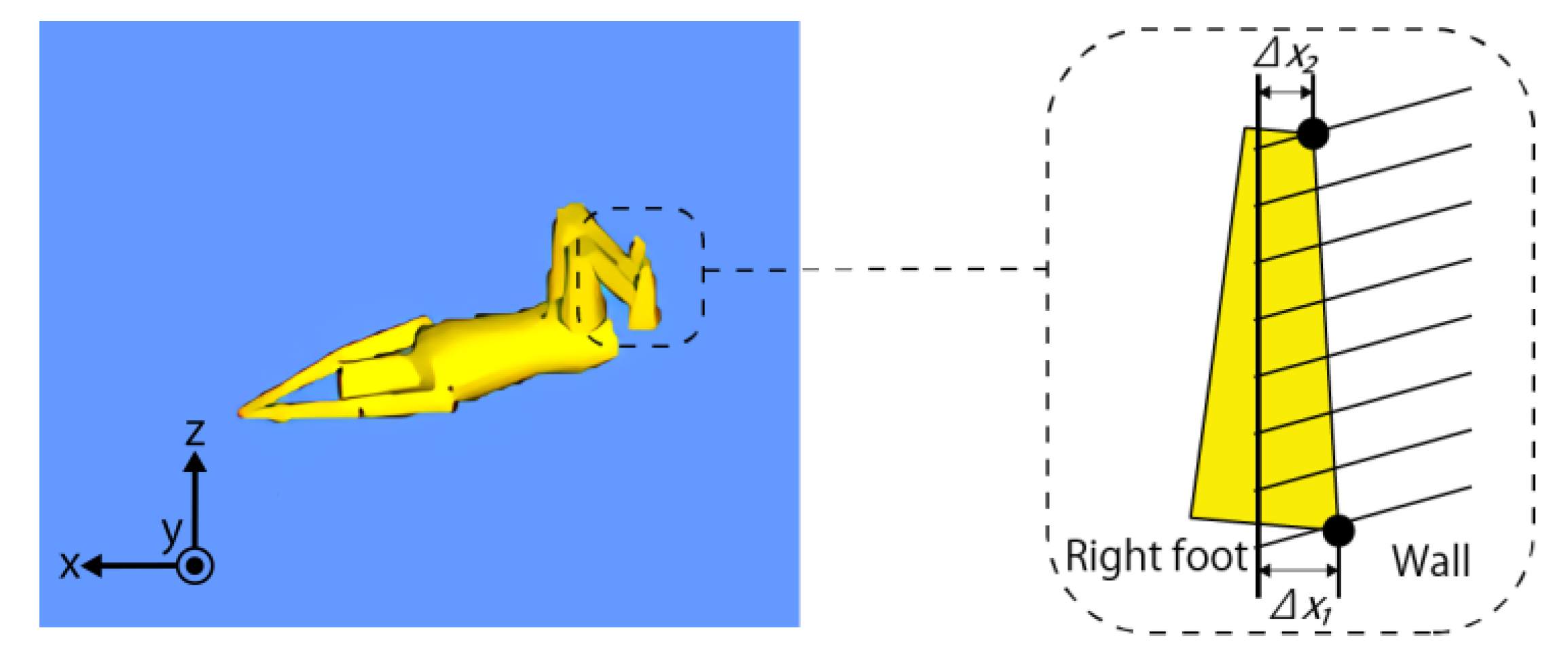
Modeling the contact with the wall during the turn is schematically shown in Figure 2. Four contact points were defined at the toes and heels of the swimmer model’s feet. An absolute coordinate system O-xyz, in which x and y are horizontal and z is vertical, was defined. The pool wall was represented as a plane where the x coordinate was a certain constant value. The contact force was assumed to be applied to the swimmer only when the x coordinate of each contact point exceeded the certain value. The exceeded amount, that is, the distance sunken in the wall, was defined as . The forces due to virtual spring and damper in the x direction perpendicular to the wall as well as the frictional force in the y and z directions were considered. The magnitude of the force by the spring is calculated from , and the magnitude of the force by the damper calculated from the time derivative of . The frictional force acts in the direction that hinders the velocity of each contact point in the y and z directions. The magnitude is determined by the force in the x direction. For example, the forces applied to the heel of the right foot in Figure 2 are represented as follows:
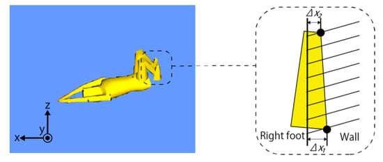
Figure 2.
Modeling the contact between both feet and the wall.
Note that is the distance sunk in the wall of the right heel; , , are the velocity of the right heel; , , are the forces in the x, y, z directions; and k, c, and are the spring constant, damping coefficient and coefficient of friction, respectively. The same formulas hold for the other contact points—the right toe, left heel, and left toe. In those cases, the subscripts become 2, 3, and 4, instead of 1 in Equations (1)~(3). The values of the spring coefficient k and the damping coefficient c were determined by trial and error. Through repeated simulations, these values were adjusted so that the swimmer’s toes left the wall immediately after the swimmer’s lower limbs were fully extended.
3. Results and Discussion
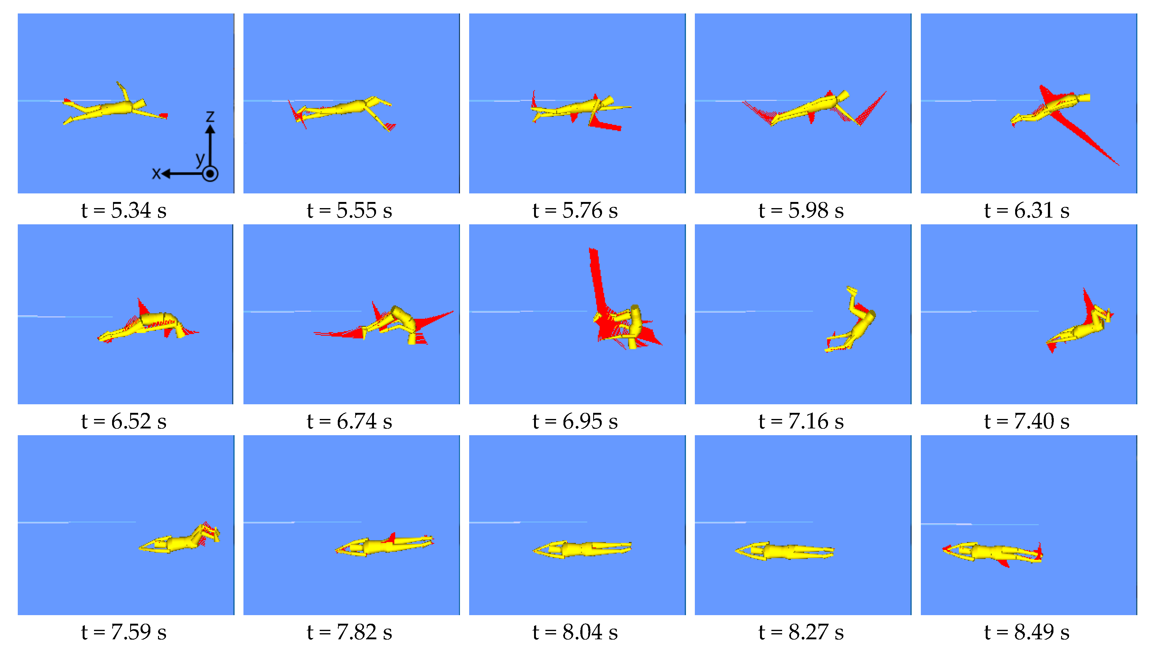
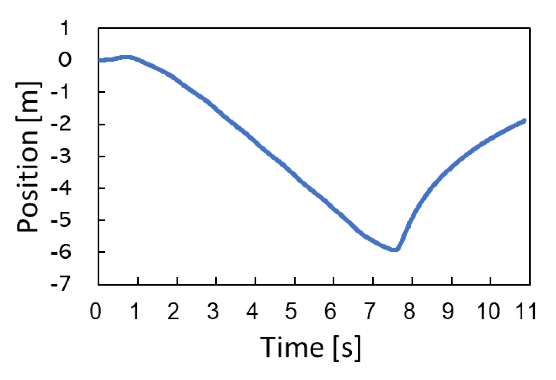
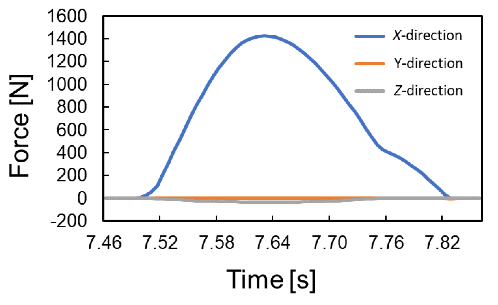
The simulated swimming motion including flip turn is shown in Figure 3. The successful turning motion was confirmed. The time history of the position of the center of mass for the swimmer in the x direction is shown in Figure 4. Note that the curve seems continuous rather than discrete, since the step of time integration was sufficiently small (0.006 s). The center of mass moved 5.9 m in the negative direction by three cycles of the crawl stroke, then a large acceleration in the opposite direction occurred due to the contact with the wall, and the swimmer moved about 4 m by subsequent kick extension and dolphin kick. The time history of the force applied to the swimmer from the wall is shown in Figure 5. The maximum force of about 1400 N was generated in the x direction for about 0.3 s. This was mostly due to the spring force, and the force due to the damper as well as the frictional force were found to be very small.
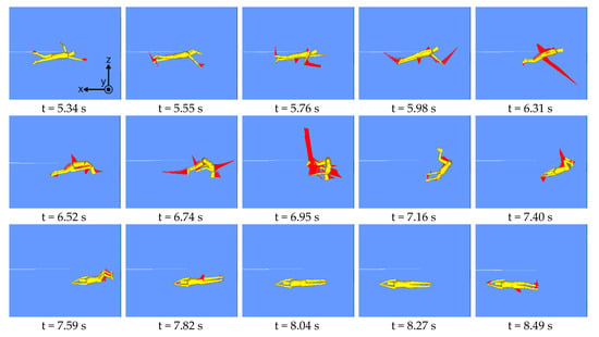
Figure 3.
The simulated swimming motion the flip turn.
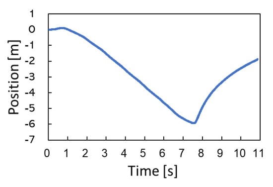
Figure 4.
Time history of the position of the center of mass for the swimmer in the x direction.
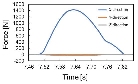
Figure 5.
Time history of the force applied to the swimmer receives from the wall.
Table 1 shows the comparison results of the contact time, maximum force, and impulse obtained by the simulation with those measured experimentally in the previous research [3]. In the previous research, three national and international level male swimmers performed a minimum of seven turns, and the results were averaged. The comparison results indicate that three mechanical quantities obtained by the simulation were within the ranges of the previous research.

Table 1.
Comparison of simulation results with previous research [3].
4. Conclusions
The simulation model of flip turn was constructed by extending the swimming human simulation model SWUM. The joint motion was created and put into the model. As a result of simulation, a successful turning motion was confirmed. It was also found that the mechanical quantities obtained by the simulation were within the ranges of the previous research. The limitation of this study was that the joint motion was created based on the standard crawl motion and a video on the Internet. Therefore, as a future task, it will be necessary to measure the actual flip turn motion and build a more precise simulation model.
Conflicts of Interest
There are no conflicts of interest to declare.
References
- Huellhorst, U.; Ungerechts, B.E.; Willimczik, K. Displacement and speed characteristics of the breaststroke turn-a cinematographic analysis. In Swimming Science V; Human Kinetics Books: Champaign, IL, USA, 1988; pp. 93–98. [Google Scholar]
- Blanksby, B.A.; Gathercole, D.G.; Marshall, R.N. Force Plate and Video Analysis of the Tumble Turn by Age-Group Swimmers. J. Swim. Res. 1996, 11, 40–45. [Google Scholar]
- Lyttle, A.D.; Mason, B. A kinematic and kinetic analysis of the freestyle and butterfly turns. J. Swim. Res. 1997, 12, 7–11. [Google Scholar]
- Araujo, L.; Pereira, S.; Gatti, R.; Freitas, E.; Jacomel, G.; Roesler, H.; Villas-Boas, J. Analysis of the lateral push-off in the freestyle flip turn. J. Sports Sci. 2010, 28, 1175–1181. [Google Scholar] [CrossRef] [PubMed]
- Nakashima, M.; Satou, K.; Miura, Y. Development of swimming human simulation model considering rigid body dynamics and unsteady fluid force for whole body. J. Fluid Sci. Technol. 2007, 2, 56–67. [Google Scholar] [CrossRef]
- Nakashima, M.; Kiuchi, H.; Nakajima, K. Multi agent/object simulation in human swimming. J. Biomech. Sci. Eng. 2010, 5, 380–387. [Google Scholar] [CrossRef][Green Version]
- HQL (Research Institute of Human Engineering for Quality Life). Measurement Database of Japanese Body Size 1992–1994 (CD-ROM); HQL: Osaka, Japan, 1997. [Google Scholar]
- Nakashima, M. Mechanical study of standard six beat front crawl swimming by using swimming human simulation model. J. Fluid Sci. Technol. 2007, 2, 290–301. [Google Scholar] [CrossRef]
- How to do a Flip Turn When Swimming | Front Crawl. Available online: https://www.youtube.com/watch?v=qLHtLzL_JMs (accessed on 15 November 2019).
Publisher’s Note: MDPI stays neutral with regard to jurisdictional claims in published maps and institutional affiliations. |
© 2020 by the authors. Licensee MDPI, Basel, Switzerland. This article is an open access article distributed under the terms and conditions of the Creative Commons Attribution (CC BY) license (https://creativecommons.org/licenses/by/4.0/).

