Proceeding Paper

Investigating the Influence of Shaft Balance Point on Clubhead Speed: A Simulation Study †

Systems Design Engineering, University of Waterloo, 200 University Ave. W, Waterloo, ON N2L 3G1, Canada
*
Author to whom correspondence should be addressed.
Presented at the 13th conference of the International Sports Engineering Association, Online, 22–26 June 2020.
Proceedings 2020, 49(1), 156; https://doi.org/10.3390/proceedings2020049156
Published: 15 June 2020

Abstract

:
In this study, a dynamic golfer model was used to investigate the influence of the golf shaft’s balance point (i.e., center of mass) on the generation of clubhead speed. Three hypothetical shaft designs having different mass distributions, but the same total mass and stiffness, were proposed. The golfer model was then stochastically optimized 100 times using each shaft. A statistically significant difference was found between the mean clubhead speeds at impact (p < 0.001), where the clubhead speed increased as the balance point moved closer to the grip. When comparing the two shafts with the largest difference in balance point, a 1.6% increase in mean clubhead speed was observed for a change in balance point of 18.8 cm. The simulation results have implications for shaft design and demonstrate the usefulness of biomechanical models for capturing the complex physical interaction between the golfer and golf club.

1. Introduction

Previous studies investigating the golf shaft’s role in generating clubhead speed have focused primarily on shaft stiffness [1,2,3,4]. These studies have brought attention to the physical interaction between the shaft and golfer biomechanics, which is not easily understood. For example, MacKenzie and Boucher [3] observed that more flexible shafts provided a higher contribution to clubhead speed from shaft bending dynamics, but were also associated with reduced grip angular velocity, resulting in no significant difference in the net clubhead speed at impact. It was also found that while more flexible shafts provide greater loft as a result of shaft bending, this increase in loft was moderated by the golfer’s tendency to change the grip orientation.
Compared to shaft stiffness, the role of shaft inertia (i.e., total mass, mass distribution, and rotational inertia) in generating clubhead speed has not been investigated to the same extent. Simple experiments have verified the benefits of lighter shaft materials (e.g., graphite versus steel [5]), but the influence of the shaft’s mass distribution on the generation of clubhead speed is not well documented. The lack of experimental evidence may be attributed to the challenge of separating the influence of the shaft balance point from other key shaft parameters, such as its total mass and stiffness. However, dynamic golfer models [6,7,8,9] offer a means for controlling these design variables while effectively capturing their physical interactions with swing mechanics.
The purpose of this study was to investigate the influence of the shaft balance point on the generation of clubhead speed using a state-of-the-art dynamic golfer model [9]. Three hypothetical shaft designs with different balance points were represented in the golfer model using a continuous analytical shaft formulation [10]. Furthermore, improvements were made to the golfer model and optimization routine to help promote the generation of realistic golf swings.

2. Materials and Methods

2.1. Shaft Modeling

Since it is well-understood that lighter shaft materials permit the generation of greater clubhead speed, this study focuses on the physical interaction between the golfer and the shaft’s center of mass position. To this end, three hypothetical shaft designs were proposed. The shafts were designed to have identical total mass and stiffness but different mass distributions. The shaft geometries are described parametrically in terms of the position, x, along the shaft axis from the butt end using the following equations:
r o ( x ) = r o , b ( r o , b r o , t ) x L t ( x ) = t 1 + t 2 x L r i ( x ) = r o ( x ) t ( x )
where r o ( x ) is the outer radius, r o , b is the outer radius at the butt, r o , t is the outer radius at the tip, t 1 and t 2 are parameters defining the wall thickness t ( x ) , r i ( x ) is the inner radius, and L is the shaft length. The cross-sectional area A ( x ) and area moment of inertia I ( x ) are then defined as:
A ( x ) = π ( r o 2 ( x ) r i 2 ( x ) ) I ( x ) = π 4 ( r o 4 ( x ) r i 4 ( x ) )
Assuming uniform volumetric mass density, the shaft center of mass position x C M is equivalent to the centroid and can therefore be defined as:
x C M = 0 L x · A ( x ) d x 0 L A ( x ) d x
The shaft’s transverse moment of inertia about the butt end I b is another inertial property of interest as it closely relates to the center of mass position. It is calculated as:
I b = ρ 0 L 1 4 A ( x ) ( r o 2 ( x ) + r i 2 ( x ) ) + x 2 A ( x )   d x  
where ρ is the volumetric mass density. The inertia term in I b resulting from the parallel axis theorem is several orders of magnitude larger than the transverse inertia term and thus
I b ρ 0 L x 2 A ( x )   d x
Table 1 provides the parameters for the three hypothetical shaft designs. All shafts were given the same outer radius profile by setting r o , b and r o , t to 8 and 5 mm, respectively. These dimensions are consistent with experimental carbon fiber composite golf shafts [10]. The shaft length was set to 1.105 m (43.5”), and the density of each shaft was calculated by assuming a total shaft mass of 65 g. Shaft A was given a constant wall thickness by setting t 1 to 1 mm and t 2 to zero. The resulting density for Shaft A was 1.561 g/cm3, which is comparable to the densities reported by Betzler et al. for sheets of carbon fiber-reinforced polymer used in the construction of golf shafts [11]. The wall thicknesses of shafts B and C were varied linearly from 0.5 to 1.5 and 1.5 to 0.5 mm, respectively, such that their average wall thickness was 1 mm.
To provide control over the effects of stiffness, all shafts were given the same stiffness profiles. A constant elastic modulus E = 68.9 GPa was used for shaft A to provide an average rigidity E I = 50 Nm2, which is representative of a regular-flex shaft [4]. For shafts B and C, the elastic moduli were varied along the shaft to generate the same bending stiffness profile as shaft A. The shear moduli were set to half the elastic moduli, such that the torsional stiffness G J of each shaft was equal to the bending stiffness E I . Figure 1 plots the inner radius, cross-sectional area, area moment of inertia, and elastic modulus profiles for each shaft. The vertical lines in the radius plot indicate the center of mass position of each shaft. Fourth-order polynomials were fit to A ( x ) , I ( x ) , E ( x ) , and G ( x ) to parametrize the analytical shaft model [10].

2.2. Golfer Model

The simulation experiments in this study make use of the dynamic golfer model presented in [9]. The referenced golfer model uses six biomechanical degrees-of-freedom (DOF) powered by muscle torque generators and a continuous analytical shaft model [10] to simulate full golf swings (backswing and downswing). Although there are DOF not captured by this model, e.g., pelvis translation, it provides good agreement to experimental results. Except where explicitly stated, the implementation of the golfer model in this study is the same as in [9].
A drawback to the golfer model used in [9] was the need to scale the shaft’s bending stiffness by a factor of 1.5 to generate realistic shaft deflections (i.e., the deflections were too great using the default bending stiffness). Upon further investigation, it was found that shaft bending could be attenuated without scaling the bending stiffness by increasing the time constants τ a c t and τ d e a c t , which control the rate of activation and deactivation of the muscle torques. The selection of the time constants used in previous golfer models [6,7,8,9] is weakly supported, and so τ a c t and τ d e a c t were increased to 100 ms to reduce shaft bending to a level consistent with magnitudes found in the literature [10]. In doing so, the rate of torque development was reduced, and so the 0.65 scaling factor that was used to reduce the maximum muscle torques in [9] was removed. Additionally, the maximum swing duration was increased to 1.2 s, which better aligns the mean swing duration from address to impact measured in golf swing experiments [10]. A more thorough investigation into the effect of the time constants on shaft bending is recommended for future work.

2.3. Golf Swing Optimization

The golfer model was optimized by finding the set of timings for the muscle torque generators that maximized carry distance, i.e., the times at which the muscles were activated and deactivated. To estimate the carry distance, the golfer model was paired with a simple momentum-based contact model [12] and a spin-rate dependent aerodynamic ball flight model [13]. It is noted that, although there are uncertainties associated with the accuracies of the respective contact and aerodynamic models, these models were sufficient for providing a proxy for the optimal clubhead delivery, and the clubhead speed associated with said delivery, which is important for this study. Moreover, the models are computationally efficient and robust, which helped reduce the computation required to run hundreds of optimizations requiring thousands of iterations each.
A number of constraints were imposed on the golf swing optimization to help promote the generation of realistic golf swings. In addition to the constraints discussed in [9], a box geometry was used to represent the clubhead shape and detect ground collisions (swings touching the ground were not considered by the optimizer). The box was 120 mm wide (heel to toe), 70 mm tall (sole to crown), and 120 mm deep, and represented the approximate size of a modern titanium clubhead. Furthermore, an adjusted carry distance, a , was used to penalize offline shots by
a = c z 2 25
where c was the actual downrange carry distance and z was the offline distance. For context, a drive that landed 25 m offline was penalized 25 m, whereas a drive that landed 5 m offline was penalized just 1 m.
A genetic algorithm (Matlab R2019b) was used to find the optimal biomechanical timings. Due to the large size of the solution space and the stochastic nature of the genetic algorithm, the optimization converged to a different solution (i.e., a different golf swing) for each randomly generated initial population. It is not possible to gauge the proximity of a particular solution to the theoretical global optimum, and so many optimizations were run, and the set of solutions were treated as a random variable. Specifically, the golf swing optimization was run 100 times for each shaft using 20 generations and a population size of 400, which provided sufficient convergence.

3. Results

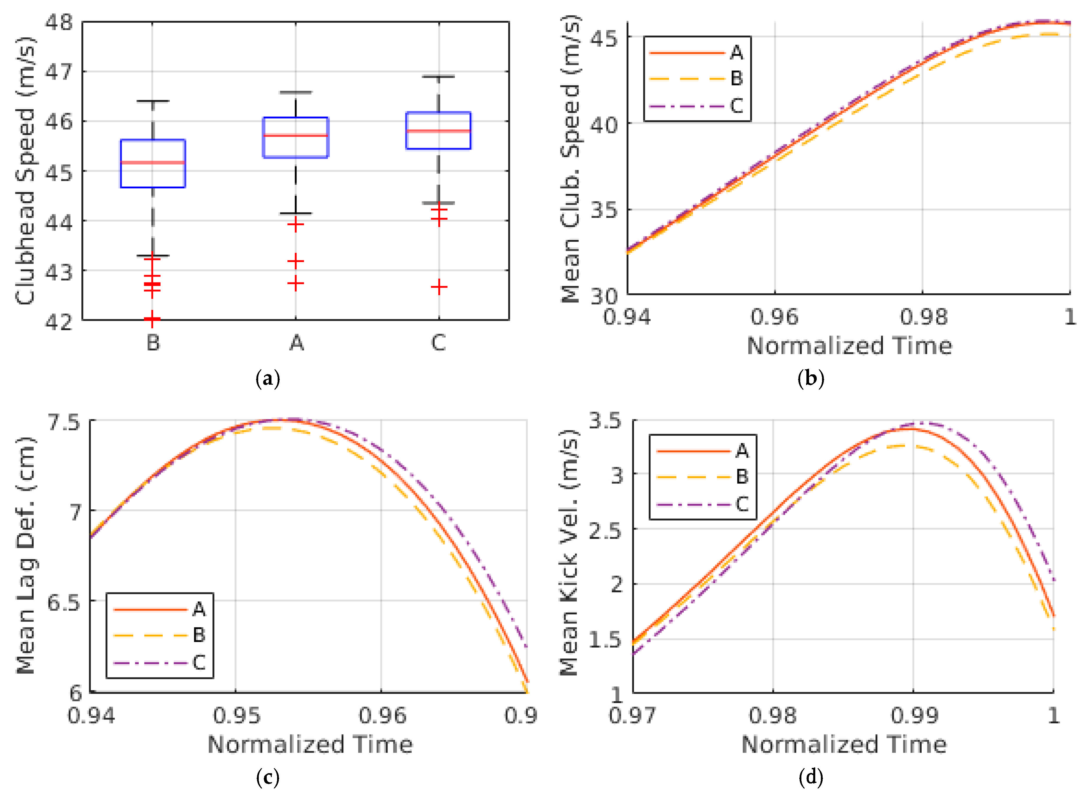
A box plot showing the distribution of clubhead speeds using each shaft is provided in Figure 2a, where the whiskers extend to ±2.7 standard deviations (±2.7σ) from the mean. The mean clubhead speeds (±1σ) were 45.0 ± 0.906, 45.6 ± 0.672, and 45.7 ± 0.644 m/s for shafts B, A, and C, respectively, which translated to a statistically significant difference (p < 0.001) using a one-way analysis of variance. However, the increase in clubhead speed as a result of shifting the balance point closer to the grip shows diminishing returns, as indicated by the similar mean clubhead speeds of shafts A and C (p = 0.11). The mean carry distances (±1σ) were 204.0 ± 11.7, 206.1 ± 10.8, and 207.5 ± 5.7 m for shafts B, C, and A, respectively.
Over the full swing, there is very little variation in the mean clubhead kinematics using each shaft. In fact, the mean clubhead speeds only started diverging approximately 100 ms before impact, as shown in Figure 2b. Upon further investigation, it was found that shaft bending dynamics played a role in this divergence. Figure 2c demonstrates that lag deflection was sustained longer using a higher balance point, resulting in an increase in kick velocity approaching impact, as shown by Figure 2d (lead/lag deflection are defined in [1], kick velocity is the derivative of lead/lag deflection with respect to time). The difference in mean kick velocity at impact between shafts A and C was 0.32 m/s, which exceeded the mean difference in clubhead speed (0.1 m/s). An explanation for why the increase in kick velocity did not translate to increased clubhead speed could be attributed to the difference in the mean angular speed of the grip at impact, which was 0.4 rad/s less using shaft C compared to shaft A.

4. Discussion

The effects of the shaft balance point on the generation of clubhead speed were investigated using a dynamic golfer model. The model provides precise control over the shaft parameters and allows the effects of the balance point to be decoupled from other shaft characteristics, such as total mass and stiffness profile. The simulation results demonstrate that a higher balance point (i.e., closer to the grip) could potentially provide an increase in clubhead speed at impact. Comparing shafts B and C, which had a difference in balance point of 18.8 cm, a 1.6% increase in mean clubhead speed is observed. To put this result into perspective, Werner and Greig [14] found that reducing shaft mass from 120 to 50 g, which is analogous to switching shaft material from steel to graphite, resulted in a 2% increase in clubhead speed. As the primary goal of driver design is to maximize carry distance, small gains in clubhead speed can provide a competitive edge to golf equipment manufacturers.
Investigating the nature of the clubhead speed increase, it was found that shaft bending dynamics play a role, despite the fact that the shafts had identical stiffness profiles. It is hypothesized that the different mass distributions may have alter the shaft kick points, which in turn leads to differences in kick velocity at impact. Notably, while shaft C produces greater kick velocity at impact than shaft A, this contribution to clubhead speed is moderated by lower grip angular speed. This trade-off was previously observed in the shaft stiffness experiments of MacKenzie and Boucher [3]. As with any simulation results, it is important to validate the findings using actual experiments.
The clubhead speed at impact also correlates inversely with the rotational inertia of the shaft about the butt, I b . However, since I b is inherently tied to the balance point in this study, this result is trivial. In future research, the rotational inertia of the shaft could be decoupled from the balance point using a common shaft geometry and different material densities. Then, a point mass could be added to the butt of the shaft to vary the balance point without affecting the rotational inertia.

5. Conclusions

A dynamic golfer model was used to investigate the influence of the shaft balance point on the generation of clubhead speed. The golfer model was stochastically optimized using three hypothetical shaft designs that had different balance points but the same total mass and stiffness. The simulation results show that the clubhead speed at impact tended to increase as the shaft balance point moved closer to the grip. Given the limitations of the dynamic golfer model, follow-up golf swing experiments are recommended to verify the validity of these findings.

Acknowledgments

The authors acknowledge financial support from McPhee’s Tier I Canada Research Chair in Biomechatronic System Dynamics.

Conflicts of Interest

The authors declare no conflict of interest.

References

  1. MacKenzie, S.J.; Sprigings, E.J. Understanding the role of shaft stiffness in the golf swing. Sports Eng. 2009, 12, 13–19. [Google Scholar] [CrossRef]
  2. Betzler, N.F.; Monk, S.A.; Wallace, E.S.; Otto, S.R. Effects of golf shaft stiffness on strain, clubhead presentation and wrist kinematics. Sports Biomech. 2012, 11, 223–238. [Google Scholar] [CrossRef] [PubMed]
  3. MacKenzie, S.J.; Boucher, D.E. The influence of golf shaft stiffness on grip and clubhead kinematics. J. Sports Sci. 2017, 35, 105–111. [Google Scholar] [CrossRef] [PubMed]
  4. Jones, K.M.; Betzler, N.F.; Wallace, E.S.; Otto, S.R. Differences in shaft strain patterns during golf drives due to stiffness and swing effects. Sports Eng. 2019, 22. [Google Scholar] [CrossRef]
  5. Pelz, D. A simple, scientific, shaft test: Steel versus graphite. In Science and Golf: Proceedings of the First World Scientific Congress of Golf; Cochran, A.J., Ed.; Spon: London, UK, 1990. [Google Scholar]
  6. Sprigings, E.J.; Neal, R.J. An insight into the importance of wrist torque in driving the golfball: A simulation study. J. Appl. Biomech. 2000, 16, 356–366. [Google Scholar] [CrossRef]
  7. Mackenzie, S.J.; Sprigings, E.J. A three-dimensional forward dynamics model of the golf swing. Sports Eng. 2009, 11, 165–175. [Google Scholar] [CrossRef]
  8. Balzerson, D.; Banerjee, J.; McPhee, J. A three-dimensional forward dynamic model of the golf swing optimized for ball carry distance. Sports Eng. 2016, 16, 237–250. [Google Scholar] [CrossRef]
  9. McNally, W.; McPhee, J. Dynamic optimization of the golf swing using a six degree-of-freedom biomechanical model. In Proceedings of the 12th Conference of the International Sports Engineering Association, Brisbane, QLD, Australia, 26–28 March 2018. [Google Scholar]
  10. McNally, W.; Henrikson, E.; McPhee, J. A continuous analytical shaft model for fast dynamic simulation of the golf swing. Sports Eng. 2019. [Google Scholar] [CrossRef]
  11. Betzler, N.F.; Slater, C.; Strangwood, M.; Monk, S.A.; Otto, S.R.; Wallace, E.S. The static and dynamic stiffness behaviour of composite golf shafts and their constituent materials. Sports Eng. 2011, 14. [Google Scholar] [CrossRef]
  12. Petersen, W.; McPhee, J. Comparison of impulse-momentum and finite-element models for impact between golf ball and clubhead. In Science and Golf V: Proceedings of the World Scientific Congress of Golf; Crews, D., Lutz, R., Eds.; Energy in Motion: Mesa, AZ, USA, 2008. [Google Scholar]
  13. Quintavalla, S.J. A generally applicable model for the aerodynamic behavior of golf balls. In Science and Golf IV: Proceedings of the World Scientific Congress of Golf; Thain, E., Ed.; Routledge: Abingdon-on-Thames, UK, 2012. [Google Scholar]
  14. Werner, F.D.; Grieg, R.C. How Golf Clubs Really Work and How to Optimize Their Design; Origin Inc, 2000. [Google Scholar]
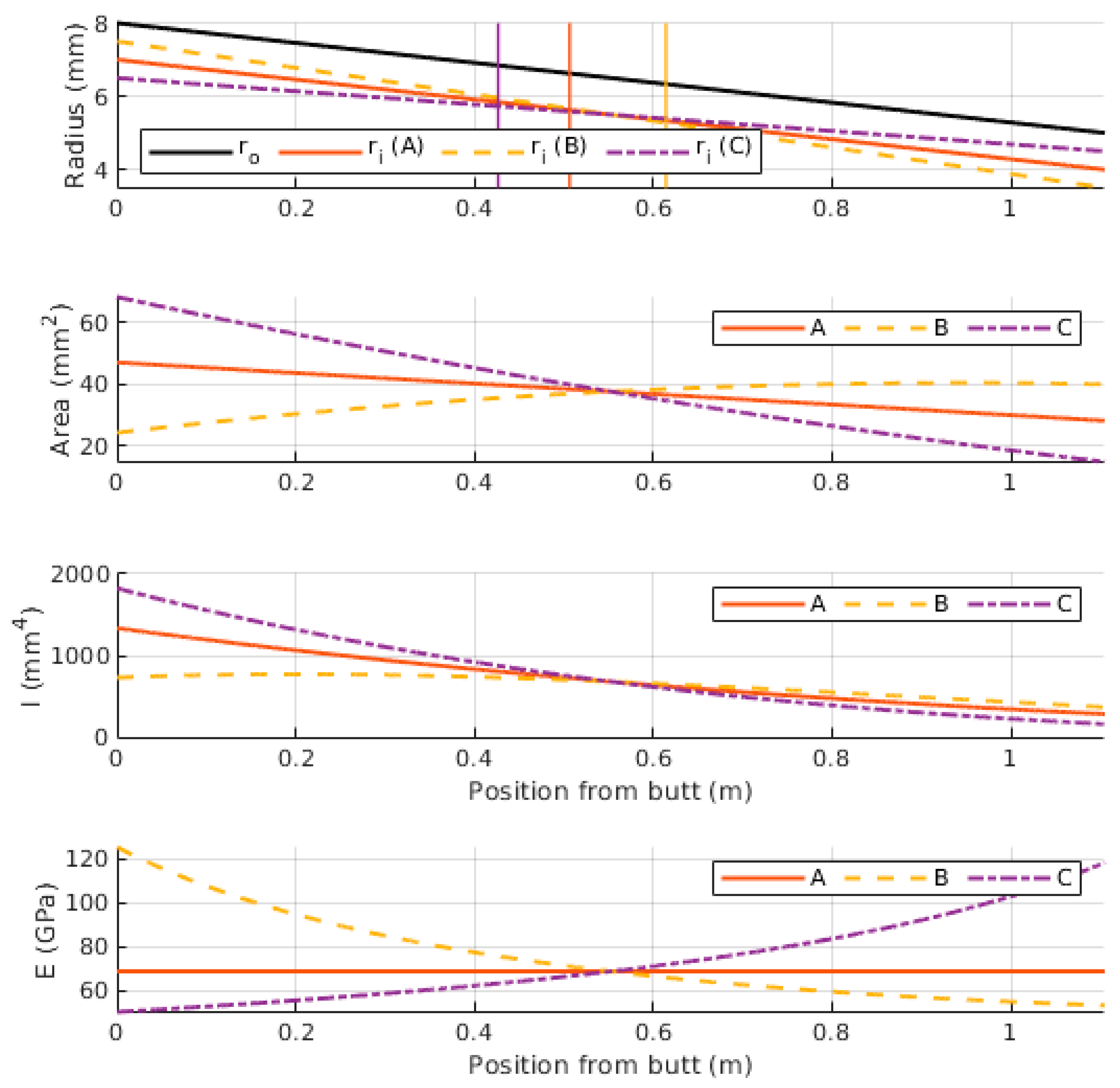
Figure 1. The inner radius, cross-sectional area, area moment of inertia, and elastic modulus profiles for each shaft design. The vertical lines in the radius plot indicate the center of mass positions of each shaft. Best viewed in color.
Proceedings 49 00156 g001
Figure 2. (a) Box plot of the 100 clubhead speeds using each shaft; (b) mean clubhead speed leading up to impact; (c) mean lag deflection during the period of max lag deflection; (d) mean kick velocity leading up to impact.
Proceedings 49 00156 g002
Table 1. Shaft design parameters. All shafts have a length of 1.105 m, total mass of 65 g, and average stiffness (bending E I and torsional G J ) of 50 Nm2.
Shaft t 1 ( mm ) t 2 ( mm ) x C M   ( m ) I b   ( g - m 2 ) ρ
A100.506423.171.561
B0.510.614331.101.897
C1.5-10.426417.581.508
Publisher’s Note: MDPI stays neutral with regard to jurisdictional claims in published maps and institutional affiliations.