1. Introduction
A treadmill is a device for walking and running in a limited space. Therefore, treadmills are mainly used for sports training and rehabilitation for a wide range of ages. A force plate is the system for measurement of ground reaction force. The evaluation of vertical and propulsion forces and the balance evaluation can be conducted by using ground reaction force [
1]. Several force plates are necessary for measurement over multiple strides. Hence, the scale and cost increase in the measurement of ground reaction force over multiple strides. The measurement of ground reaction force over a long distance can be conducted by installing a force plate to the treadmill. A treadmill installed with force plate has been used for the measurement and analysis of running and walking, and a treadmill installed with force plate can control the belt speed [
2].
A self-driven treadmill has been developed for measurement and evaluation of anaerobic power in sprint running. The treadmill can conduct the power evaluation close to actual motion. Therefore, a treadmill using tractive force, handrails, and a curved shape has been developed [
3,
4,
5]. These self-driven treadmills can generate load using a mechanical system. Hence, detailed adjustment of load control can be difficult on treadmills. The treadmill installed with the force plate can measure the propulsion force and control speed. Therefore, the treadmill can control the load by installing an automatic controller using propulsion force. In this study, we developed a load control type treadmill using a treadmill installed with a force plate and an automatic controller. We analyzed and measured motion using the treadmill and a wearable sensor system, and we indicated the effectiveness of load control type treadmill by the results of motion analysis.
2. Materials and Methods
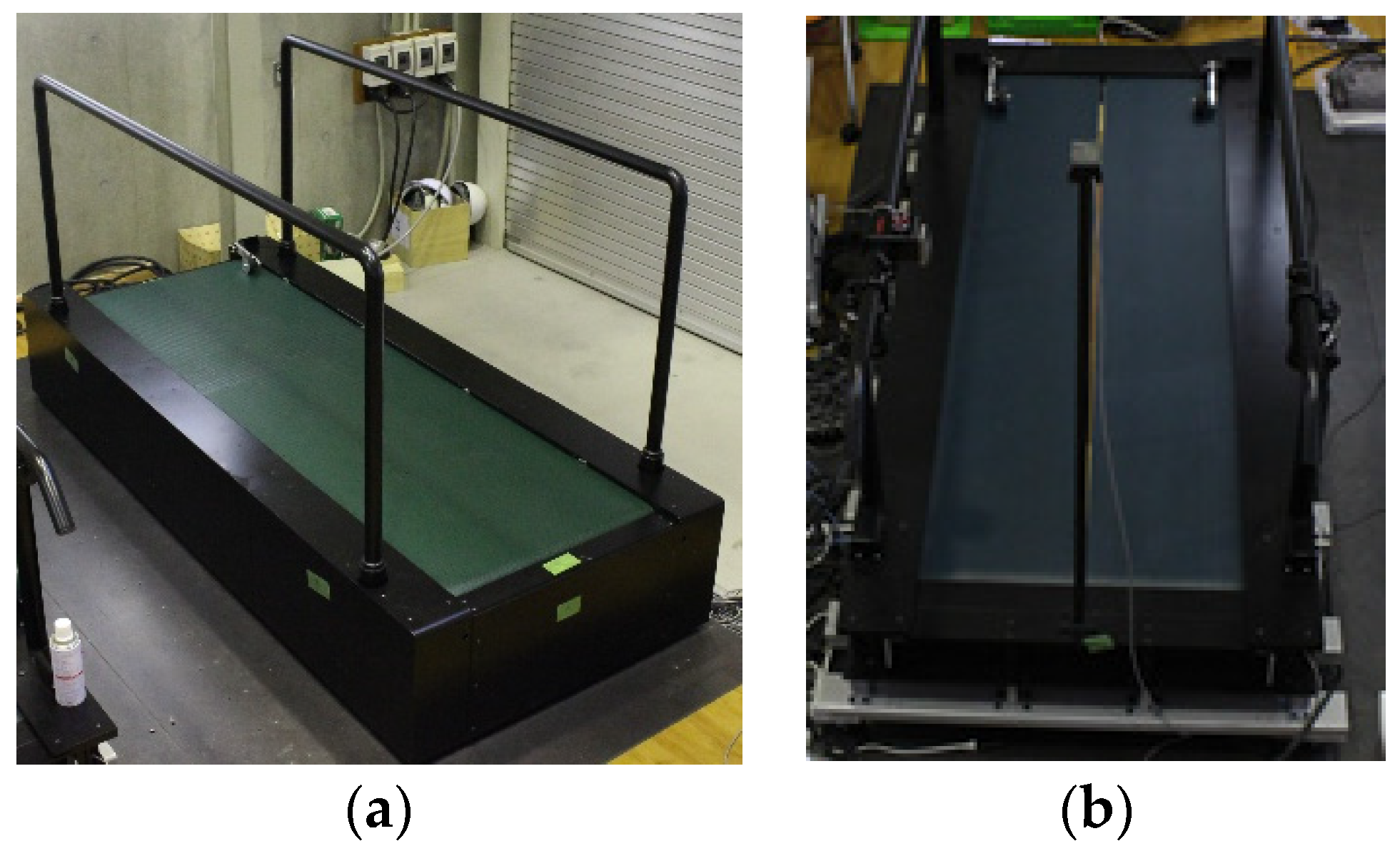
2.1. Treadmill Installed with a Force Plate
The treadmill installed with a force plate is shown in
Figure 1. The treadmill comprises a force plate and measures force and moment. There are single-belt and dual-belt treadmills in the treadmill installed with a force plate. The single-belt treadmill installed with a force plate is mainly used for the analysis of running performance in sports. The dual-belt treadmill installed with two force plates is used to measure the ground reaction forces of left and right feet, and the treadmill is mainly used for gait measurement and analysis. In this study, we used the dual-belt treadmill, and the measurement area was 1600 × 600 mm [
6].
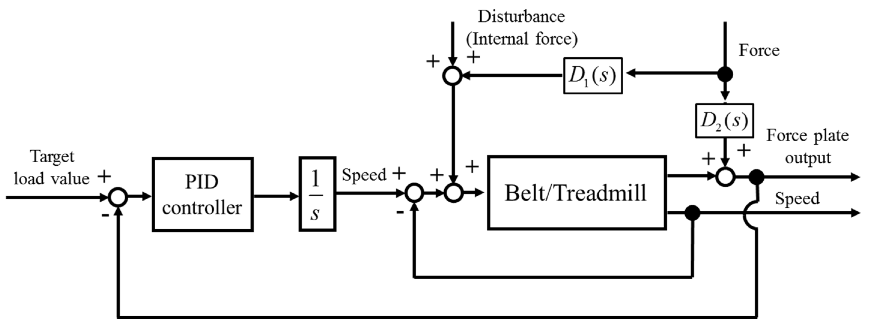
2.2. Load Control System by Treadmill Installed with a Force Plate
A load control system applies a feedback system using a force plate output. A block diagram of the load control system is shown in
Figure 2, where
s is a Laplace operator, and
D1(
s) and
D2(
s) are disturbance factors. The target value is a specified value determined by the load, and the control input is the speed. The control output is a propulsion force in force plate output, and the control output is fed back. The automatic controller consists of a PID controller, an integrated circuit, and a speed controller installed with the servo motor amplifier. The propulsion force is measured by shearing force in force plate output. The propulsion force consists of the friction force and the force acting on a drum and a motor. These force factors are treated as a disturbance in the control system. The disturbance by force acting on the motor and the internal force generated by the tension force of the belt are suppressed by the speed controller. The friction force and the force acting on the drum are small due to the low friction between the belt and the plate on the treadmill and the low inertial drum. The top plate of force plate is connected to the drum and the motor to measure the total propulsion force.
2.3. Estimation Method for the Joint Angles
Joint angles were estimated by the sensor fusion algorithm using the Extended Kalam filter and the inverse kinematics. The sensor fusion algorithm was designed using the algorithm based on the Kalman filter in the previous study [
7]. The performance of the estimation method was indicated in the previous study; therefore, the method can be used for the analysis of this study. The nonlinear state equation and measurement equation are shown in Equations (1) and (2). The covariance matrix of a measurement value is shown in Equation (3). The matrix consists of the acceleration and the sensor noise factors, and the acceleration factor is represented by combined acceleration data.
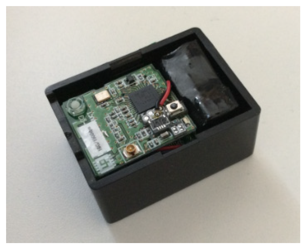
2.4. Experimental Conditions
We conducted measurement experiments using ground reaction force and a wearable sensor system. The participants gave informed consent before the experiment. The analysis using ground reaction force was conducted in running conditions at constant belt speed, low target load (10 N), and medium target load (30 N). Motion analysis using the wearable sensor system was conducted in gait conditions of low target load, medium target load, and high target load. The wearable sensor system used an inertial and magnetic field sensor system (Wireless motion sensor, Logical Product, Fukuoka, Japan). The sensor system is shown in
Figure 3. The measurement time was 30 s. The sampling frequency was 1 kHz. In the measurement experiment of running conditions, a participant traveled on the treadmill at a specified speed (about 10 km/h), and the participant was fixed and towed using a lumber belt. In the gait analysis condition, a participant wearing the wearable sensor system walked on the treadmill in a specified load condition (10, 30, and 70 N), and the participant held hand rails in the gait measurement. The wearable sensors were attached to the femur, lower thigh, and foot.
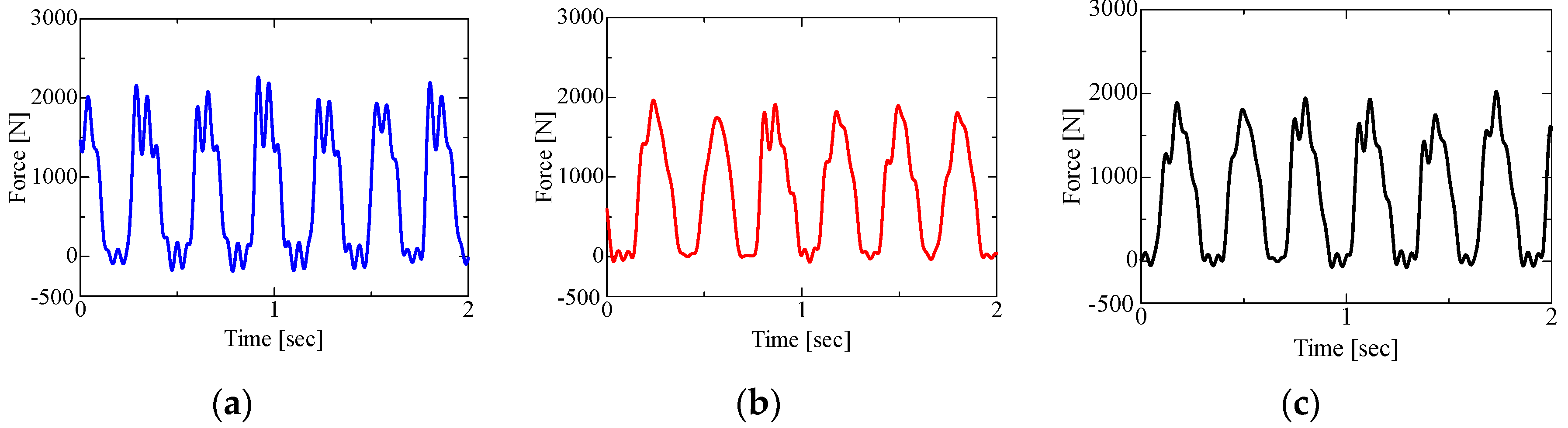
3. Results
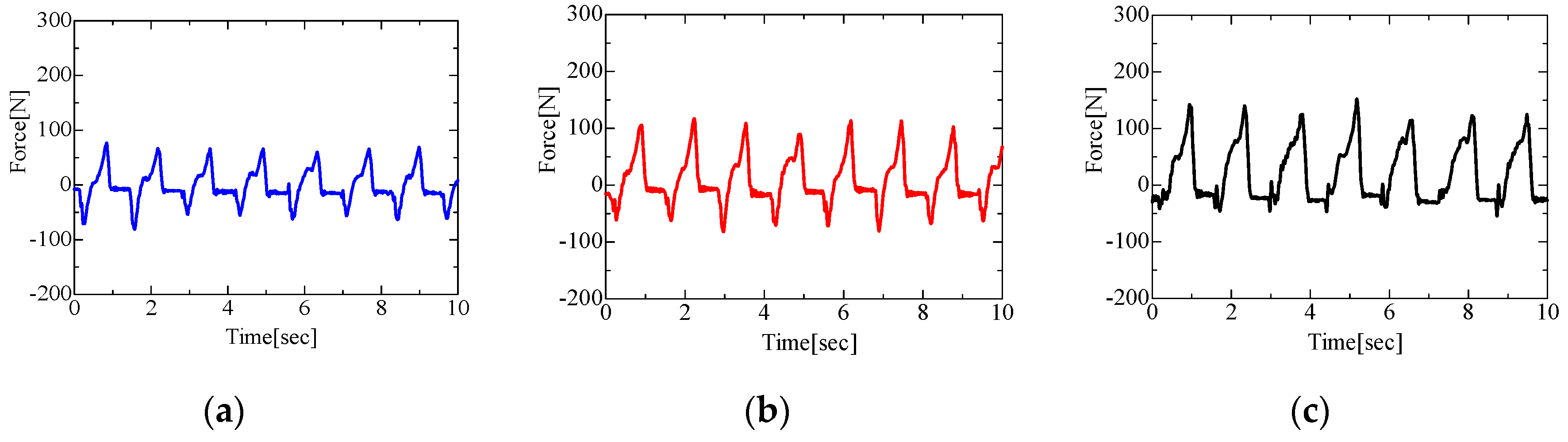
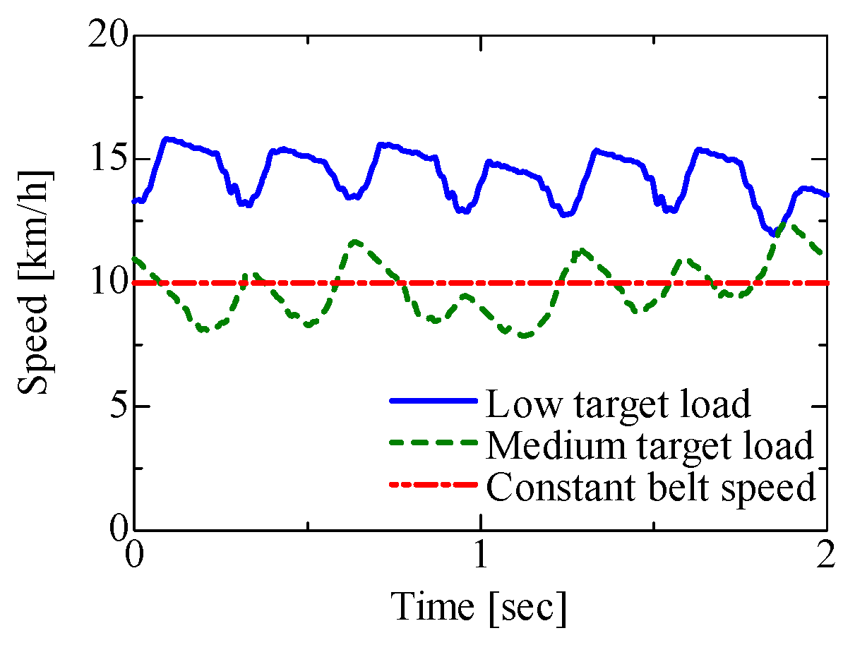
Results for the ground reaction force of the right foot and the running speed in running conditions are shown in
Figure 4,
Figure 5 and
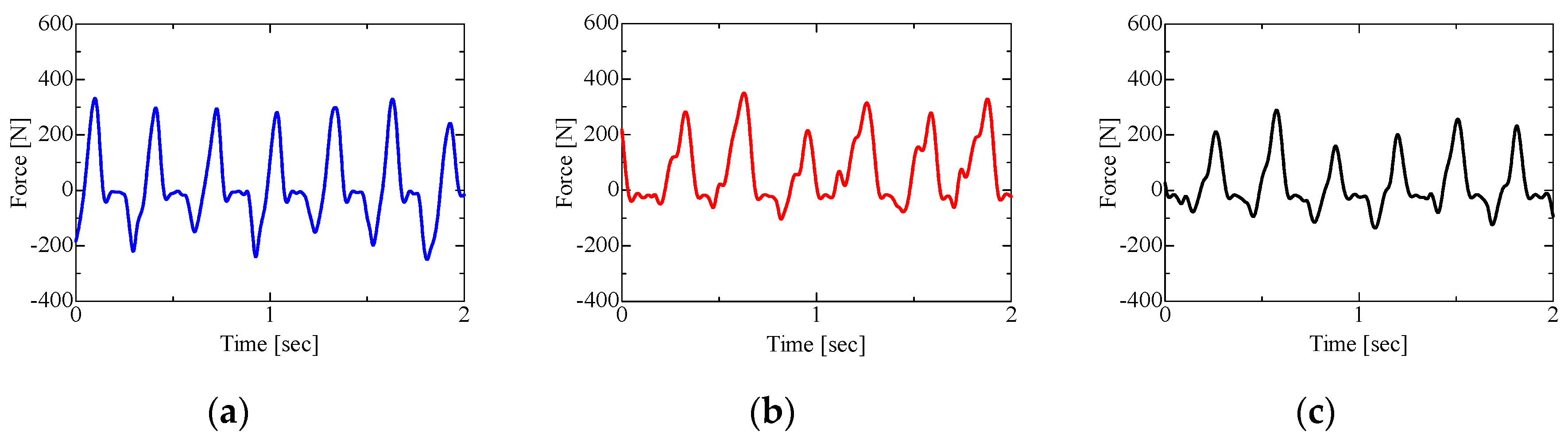
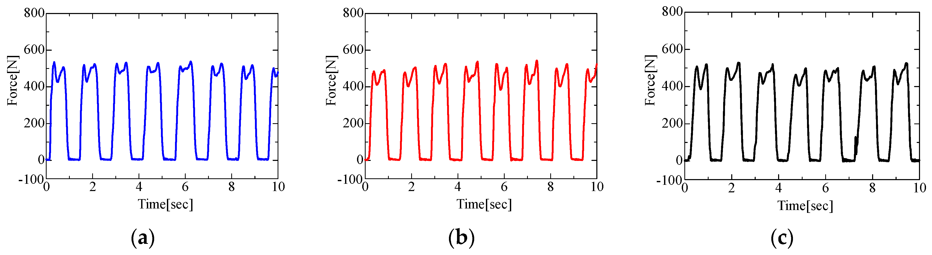
Figure 6. Results for the ground reaction force in gait are shown in
Figure 7 and
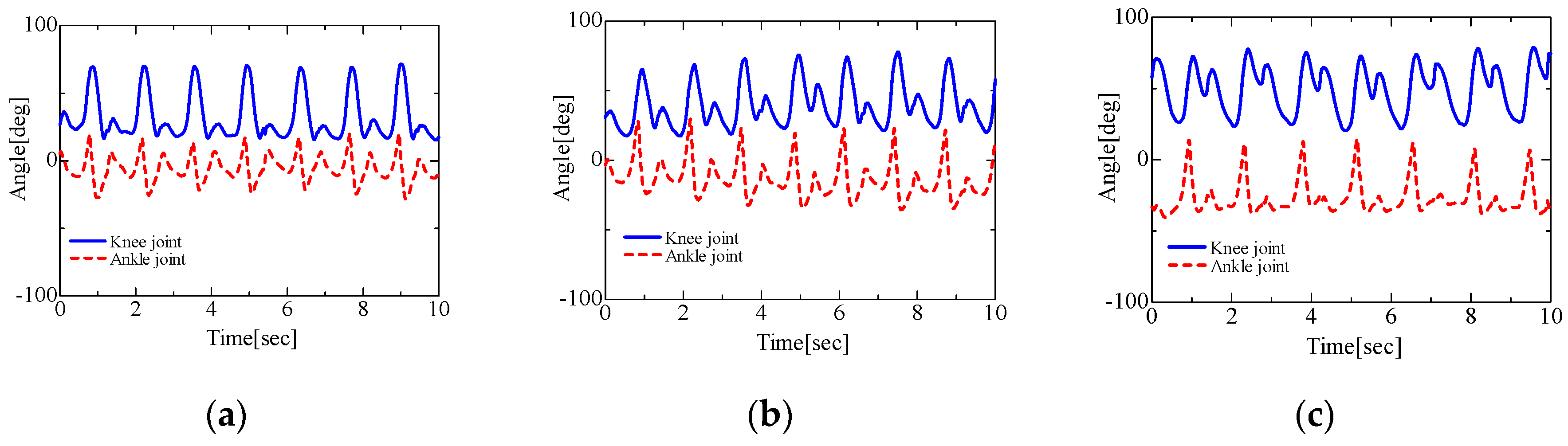
Figure 8, and results for the joint angles of right lower limb in gait are shown in
Figure 9.
4. Discussion
For the vertical forces, these results indicated a similar trend in all results. For the propulsion forces, the result of load control mode in the low target load value indicated a brake force (negative value), and the results of constant speed and load control in the medium load value did not indicate a brake force. However, the results of load control in the medium load value indicated a high propulsion force against generating speed. In running on an actual road, the ground reaction force of the propulsion and brake forces are generated. When the belt runs at a constant speed, participants may not always generate the propulsion forces because the belt works automatically. However, the propulsion forces are always generated on an actual road. Therefore, these results indicate that the load control in the low target value can be closer to running on an actual road.
The results for the ground reaction force in the low target load value indicated propulsion and brake forces, and the results indicated similar trends in the running experience. The results for the ground reaction force in the high target load value indicated high propulsion, and the results indicated reaction force against the generated load. In the results for joint angles, the characteristics of ankle and knee joint angles changed with the increase of target load. The plantar flexion angle increased in the ankle joint, and the flexion angle increased in the knee joint with the increase of load. These results indicate that the participant generated the reaction force against the load by maintaining the joint angles. The analytical results indicated the characteristics of the load control type treadmill.
5. Conclusions
In this study, we developed a load control type treadmill installed with a force plate and an automatic controller, and we conducted measurement experiments on the load control type treadmill using a wearable sensor system. Estimation and analysis of motion are conducted to represent vertical and propulsion forces and joint angles. The differences in motion between the levels of the target load value are indicated. The estimation and analysis method using the wearable sensor system can provide measurement information directly from the sensor system. It is necessary to conduct more experiments in order to indicate the method that can be used for the evaluation of training or rehabilitation effectiveness using the treadmill in future work.
