2. Improving the Hydrodynamic Design of Finn Rudders within Class Rule Limits
The function of a rudder is to provide an adjustable yawing moment, necessary for controlling the sailing direction. By changing the rudder angle, the sailor can adjust the amount of side-force (i.e., lift) generated, and thus also the yawing moment.
In addition to generating side-force, the rudder will also generate drag. Three forms of drag can be identified: skin friction drag, pressure drag and induced drag [
4]. When the rudder is deflected, induced drag becomes the dominating component [
4]. It is a direct consequence of generating side-force with a finite span rudder. At the top and bottom of the rudder, vortices are created, which modify the flow, reducing side-force and creating induced drag. The magnitude of the induced drag is closely related to the effective aspect ratio, determined by the distance between the tip vortices.
The effective aspect ratio can easily be increased by increasing the span (i.e., draft) of the rudder. However, the Finn dinghy class rules [
3], prohibits any significant increases in span, since both the external shape of the rudder and the positioning relative to the boat is closely controlled by the rules.
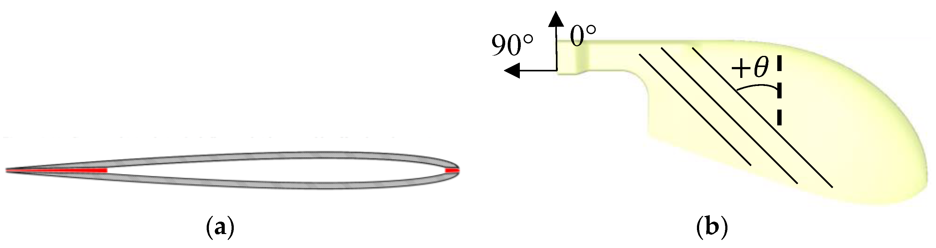
The planform shape of the rudder is defined with a template. Below the measurement waterline, the shape of the rudder is allowed to deviate ±5 mm from the template. The chord length and thickness of the rudder section are also limited, and may not exceed 365 mm and 23 mm, respectively. The allowed planform tolerances are too small to achieve any meaningful increase in aspect ratio by changing span alone. Instead, other solutions to increase the effective aspect ratio must be found.
On a planform with a rounded tip, the vortex tends to climb up the trailing edge, reducing the effective aspect ratio. However, by adding a small kink (e.g., a vortex tip) on the planform outline curve, shedding of the vortex can be triggered. With correct positioning, the vortex will be shed as far down as possible, which increases the effective aspect ratio.
In addition to planform shape, cross-section shape is also critical for performance. In Reference [
3], large differences in the high angle of attack handling characteristics were found. In order to achieve benign behaviour at high AoA, a NACA four-digit series section was chosen. These sections are well proven for use for rudders [
4]. Finally, the rudder brackets were designed to position the leading edge as close as possible to the transom to improve hydrodynamic performance.
In order to evaluate the performance of the improved design. Computational Fluid Dynamics (CFD) simulations were performed for the improved design and for a 3D-scanned, commercially available rudder (from Reference [
2]). Three rudder angles were tested, 0, 5 and 10 degrees. The simulations included the dinghy hull. The free surface was modelled with a Volume-of-Fluid technique. The flow was modelled as fully turbulent using an SST K-Omega turbulence model, with low Y+ wall treatment. The performance was evaluated by comparing the side-force, drag, and the side-force to drag ratio, at each rudder angle.
Figure 1 shows the suction side pressure distributions, predicted by CFD, at 10° rudder angle. The black lines show the tip vortex core, illustrating the effect of the improved planform shape on the position of the tip vortex. For easier comparison, the reference tip vortex is shown superimposed on the simulation of the improved rudder.
The simulation results are shown in
Table 1. At 0° rudder angle, the improved rudder shows significantly reduced drag, by 16.5%. For 5° rudder angle, the SF/D ratio is slightly improved, by 0.61%. For 10° rudder angle, the SF/D ratio is dramatically improved, by 22.6%.
3. Material Selection and Structural Design
To keep the rudder at minimum weight imposed by the class rules—a minimum of 4 kg in total for the rudder, tiller, tiller extension and fittings—carbon fibre reinforced polymers (CFRPs) were used as the base material type in the design. To avoid a too brittle design, high strength carbon fibres were desirable, although at a reasonable cost. In addition, both unidirectional reinforcements plies, as well as plies with woven reinforcement (for better impact protection), were required in the design. Additionally, it was desired to cure the components out of an autoclave (at 1 bar pressure). These aspects together led to the choice of one UD system: (XPREG XC130 Prepreg Carbon (Toray T700S) 3K, 300 gsm) and one woven system (XPREG XC110 Prepreg Carbon (Pyrofil TR30S) 3K, 210 gsm, 2/2 Twill) both with a toughened epoxy resin system and both sourced from Easy Composites Ltd. Key properties for these materials could be obtained from Technical Data Sheets for each system [
5,
6,
7]. The remaining data were estimated from data for a similar material system (same stiffness) taken from the material database in the finite element software ANSYS [
8]. All the data used for the design can be found in the
Tables S1 and S2 in the supplementary material.
CFRP was complemented with a foam core in the rudder to achieve a hollow design with sandwich sheets (see more below). The foam type was Divinycell HP100 sourced from Diab Group. The reasoning for choosing a foam core over a honeycomb material was mainly that foam is easier to process into the required shape. Data for the foam is available in [
9].
3.1. Design Load Cases and Requirements
Two load cases were considered in the structural design of the rudder system: Normal sailing condition and Sailor supporting condition, where the latter is an idealisation of the case when the sailor leans or falls on the tiller or tiller extension. Furthermore, the rudder steering angle should be at least 60° to either side.
The structural requirements for the rudder, tiller and tiller extension system were defined as:
No composite part should have a safety factor to failure lower than 1.2. To assess the risk of failure, the Tsai-Hill and maximum stress damage criteria were used.
The tiller should be stiff enough not to deflect to the extent that it hits the hull when subjected to the Supporting sailor condition (point load of 1 kN).
The maximum rudder blade deflection under normal sailing conditions should be smaller than what is estimated for existing commercially available rudders. This is an order to preserve high hydrodynamic performance.
To determine a suitable layup of the rudder, finite element analyses representing both load cases were conducted using ANSYS [
8]. The entire rudder and a small part of the tiller (150 mm) closest to the rudder were modelled. The rudder-tiller connection was modelled as a bonded contact, where the inner surface of tiller was tied to the outer surface of the rudder head. Furthermore, the rudder was supported at the holes for the rudder brackets by cylindrical supports (displacement fixed in radial and axial direction but free in the tangential direction). The loads for the normal sailing conditions were derived from Computational Fluid Dynamics simulations, giving a pressure distribution over the rudder blade surface with a maximum pressure towards the bottom of the rudder of almost 400 kPa (for the full pressure distribution, see
Figure S1 in the supplementary material). Furthermore, the load for the
sailor supporting condition was represented by a point load at the tip of the tiller (where it connects to the tiller extension) of 1 kN (see also
Figure S2). This was applied to the rudder model through a remote force in ANSYS, converting the remote point load to a force and moment load at the end of the tiller part.
To determine a suitable layup of the tiller, another ANSYS finite element model was considered. Again, the attachment between the tiller and the rudder head was included in the model the same way as described above. However, this time the full tiller was included in the model whereas the rudder geometry that was “cut” just below the joint, and the cut surface was modelled as clamped. Furthermore, the idealised point force was applied on the lower front edge of the tiller.
3.2. Rudder Concept
To comply with the requirements of having a very light and stiff design, a hollow sandwich design, as shown in
Figure 2a was chosen. The complex geometry of the rudder blade makes it difficult to laminate as one. That led to that the rudder needed to be designed as laminated in two halves, to be joined in a secondary gluing operation. To secure a strong bond, particular focus was put on designing large internal surfaces (marked in red in
Figure 3a).
With the geometrical shape from
Section 2, the rudder design was iterated to meet the structural and non-structural design requirements, finally resulting in the design shown in
Figure 2b. Inspired by the rudder on the winning Finn dinghy at the 2016 Olympics, a cut-out was introduced in the upper part of the rudder in order to optimise its mass distribution.
From the finite element analysis results, it could be concluded that a suitable layup for the rudder is [0
W/60
UD/30
UD/60
UD/0
W/2.5 mm foam core]
S where •
W and •
UD denote weave and unidirectional reinforcement, respectively, and where the reinforcement angle is with respect to the coordinate system in
Figure 2b. It is emphasised that having a woven ply on the outside increase the impact performance, as well as the surface finish.
This layup resulted in a maximum deflection of the rudder of 5mm, and a minimum safety factor against the intralaminar failure of 1.3 (except for in specific points where stresses were over-predicted, due to the contact modelling).
3.3. Tiller Concept
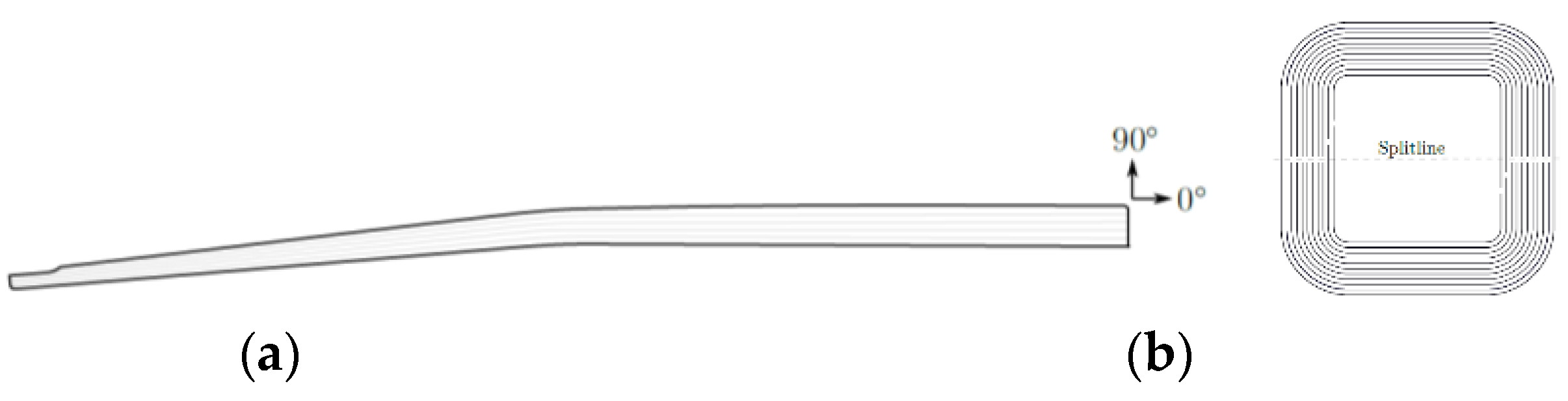
The tiller has been designed as a monolithic, hollow CFRP part, to be laid up in two female moulds. It consists of two straight sections with a downward kink right at the edge of the aft deck, see the sketch in
Figure 3a. The first section follows the aft deck, and the second section is angled downwards as much as possible without it hitting the side of the cockpit when steering. The cross-section is square (50 × 50 mm) in the rear end where it connects to the rudder, and gradually tapered down to rectangular (20 high × 32 wide) at the front end.
From the finite element analysis results, it could be concluded that a suitably layup for the tiller is [45
W/0
W/0
UD/10
UD/0
UD/
UD]
S. The 45 plies were included primarily to counteract any bending shear stresses, but they also provide additional torsional stiffness and strength. The 0 woven ply introduces fibres in the circumferential direction, which account for unexpected loads and contribute to the hoop resistance of the tube. Together, they also reinforce the split line generated by most of the UD plies, see
Figure 3b. Please note that also two innermost UD plies which were made to overlap to further strengthen the tiller along the split line. In addition, the 10° offset of some UD plies (from the longitudinal direction) was chosen to avoid washing during the manufacturing.
With this design and layup, the maximum deflection was predicted to be just above 5 cm (at the tip of the tiller). More interesting, however, is the deflection at the downward kink, which is about around 14 mm, just enough not for the tiller to hit the hull in this case. In addition, the minimum safety factor predicted for any part of the tiller was again approximately 1.3 (except for in specific points where stresses were over-predicted, due to the contact modelling).
3.4. Assembly and Mountings
The tiller is attached to the rudder with a mortise and tenon adhesive joint using adhesive. A cut-out in the bottom side of the tiller acts as the mortise hole and the top of the rudder head is be designed as a rectangular block, forming the tenon tongue. Further, to simplify the manufacturing, and to make brackets exchangeable it was decided to use mechanically attached rudder brackets
4. Manufacturing
Moulds for the rudder and the tiller were both designed as negative (also called female) split-moulds made from epoxy blocks. The mould halves were designed with a thickness 2 mm below the stock material, allowing (and necessitating) the mating surfaces to be face-milled (and thereafter grinded) to ensure a perfect fit.
It turned out to be most suitable to manufacture each half of the rudder using the following a 3-step cure (1. outer skin, 2. outer skin + adhesive film + foam core, 3. outer skin + adhesive film + foam core + adhesive film + inner skin). A so-called “Extended Soak Cycle” was used for the curing at max temp 120 °C. More in detail, the woven layers were laid up in one piece and thereafter cut and trimmed once in place. However, as UD cloths permit only very little shearing during the layup, these layers were instead added in 3 cm wide strips. After both rudder halves were cured, they were trimmed for optimal fit, and metal inserts were glued on the inside of one of the halves, where after the two halves were glued together.
In contrast to the rudder, the tiller was manufactured as one part, cured in one step. This necessitated an internal bagging operation for the curing. Furthermore, to avoid wrinkle-formation during manufacturing, the UD fabric for the tiller geometry was divided into more than 100 individual pieces, each curved only in one direction. However, thanks to these pre-cut pieces, the layup of the tiller was straightforward. The woven plies, on the other hand, could be placed as whole pieces trimmed in place. Before closing the mould, small pieces of peel-ply were placed at both ends of the part to ensure two rough surfaces for the bonding of the rudder head and the tiller insert.

 ,
, 

