Proceeding Paper

Effectiveness of a Snowboarding Simulation Using the Distinct Element Method †

1
Faculty of Engineering, University of Fukui, 3-9-1 Bunkyo, Fukui 910-8507, Japan
2
Graduate school of Engineering, University of Fukui, 3-9-1 Bunkyo, Fukui 910-8507, Japan
*
Author to whom correspondence should be addressed.
Presented at the 13th conference of the International Sports Engineering Association, Online, 22–26 June 2020.
Proceedings 2020, 49(1), 101; https://doi.org/10.3390/proceedings2020049101
Published: 15 June 2020

Abstract

:
Some snowboarding simulation methods have been developed. Although snow has unique properties such as granular material and continuum, few snowboard simulation methods can reproduce the discrete behavior of snow. Conventional simulations are unsuitable for reproducing the characteristics of snow when ski and snowboard turns carve through snow and create grooves in it with their edges. We developed a snowboarding simulation based on the distinct element method (DEM) to reproduce the characteristics of snow and compare the results of the developed method with those of a conventional simulation method. The developed simulation was validated by comparing with the results of an experiment involving a few miniature snowboards of different shapes and a pseudo-snow slope. The turn trajectory and board posture predicted by the DEM simulation were closer to the test results than those predicted by the conventional simulation.

1. Introduction

To develop new products, snowboard and ski manufacturers usually rely on a trial-and-error process. In this process, the performance of prototypes is evaluated by test riders on the basis of their sensibilities. Then, designers tune the characteristics of the prototypes based on the subjective opinions of the riders. An alternative approach for evaluating the performance of prototypes involves developing numerical simulations to model the key aspects of snowboarding performance.
A few skiing and snowboarding simulation methods have been developed and reported in the literature [1]. These simulation models cannot calculate the reaction forces due to the unique properties of snow, such as its discrete behavior, because they model snow only as a continuum. Therefore, these methods are unsuitable for reproducing snow in some cases in which ski and snowboard turns carve through the snow and create deep grooves in it with their edges. Furthermore, the forces acting on the bottom of the board, which are examined in fields and on a bench [2,3], exhibit nonlinear characteristics due to the deformation of snow, and the board bottom pressure causes frequent shear fractures [4]. Therefore, the snowboard design process must consider the discrete behavior and plasticity of snow for analyzing the kinematics of snowboards. For this reason, Mössner et al. have developed an interaction model between the ski and snow based on the plasticity of snow [5].
The distinct element method (DEM) can be used to reproduce the discrete behavior of snow [6]. We developed a simulation based on the DEM to reproduce the behavior of snow by calculating the interaction forces between the board and snow [7]. Moreover, following the conventional study [1], we developed a linear spring model as well. This simulation can be conducted to calculate the reaction force acting on a snowboard due to snow based on the penetration depth of the snowboard into a snow slope to reproduce the board’s behavior. To validate the effectiveness of the proposed DEM simulation method, we compared the simulation results with the results of a test conducted in this study. For this test, we created an experimental slope by using small plastic pipes and three types of boards of different shapes. In the test and the simulation, the snowboarding trajectories, postures, and velocities were compared for each of the three boards.

2. Mechanism of Snowboard Turn

Figure 1 shows the coordinate system and the direction of rotation of the board. The origin of the coordinate system is the center of the board. The X-axis is set along the direction of travel of the board, Y-axis is set along the width of the board, and Z-axis is set vertically to the board.
Figure 2 shows a snowboard in the primary stage of a turn. Attack angle is the angle formed by the traveling direction of the board with the centerline of the board. Snowboarders generate the attack angle by twisting their bodies. Because the reaction force component acting in the direction opposite to the direction of travel affects the lateral motion of the board, the attack angle allows the snowboard to turn. Figure 2b illustrates a view of the snowboard as seen from the front in the direction of travel. The edge angle is the angle between the snowboard and the snow surface. An increase in the edge angle changes the direction of the reaction force acting on the board. The reaction force can be decomposed in a direction parallel to the snow surface. This component force allows the snowboard to turn. Furthermore, the sidecut, which is the circular arc on the side of the board, affects snowboard movement. The sidecut penetrates the snow surface by the increasing edge angle, and the groove formed by penetration of the board’s edge into the snow constrains the motion of the board. Therefore, the sidecut influences the turning radius of the board. In general, boards with a smaller sidecut radius tend to have a smaller turning radius.

3. Simulation Method

3.1. Snow Model in Distinct Element Method (DEM)

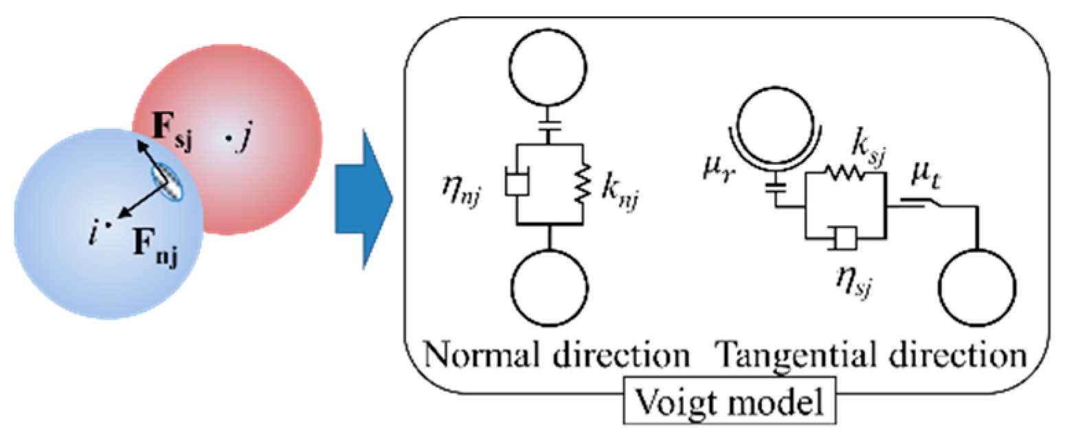
In this simulation, snow was modeled with particle elements. Particle behavior was calculated using the DEM by considering rolling friction [8]. The DEM model proposed herein, which is based on the Voigt model depicted in Figure 3, calculates the contact force between snow particles. In Figure 3, k is the spring coefficient, η is the damping coefficient, and μ t is the friction coefficient. The subscripts n and s indicate the normal direction and the tangential direction, respectively. By setting these parameters appropriately, we could use the DEM to reproduce the discrete behavior of snow. The motion equations describing the behavior of particles i are expressed as follows:
m i d 2 w i d t 2 = m i g + F n j + F s j
I i d 2 θ i d t 2 = T j
Here, m i is the mass of particle i , w i is the position vector of particle i , and g is the vector of gravitational acceleration. F n j and F s j are the contact force vectors applied by particle j in the normal and tangential directions, respectively. In Equation (2), I i is the moment of inertia and T j is the rotational moment vector generated by the tangential force. Because the plastic pipes used in the validation test were not spherical, we considered rolling resistance M t in the simulation. Equation (3) expresses the rotational moment of the particles, and Equation (4) expresses the rolling resistance M t . μ r is the rolling friction coefficient, r i is the particle radius, and s g n ( · ) is a sign function.
  T j = { r F s j M t                                                                               | r F s j | > | M t |   0                                                                                                                 | r F s j | | M t |
M t = μ r r i F n j s g n ( r F s j )

3.2. Conventional Snow Model (Linear Spring Model)

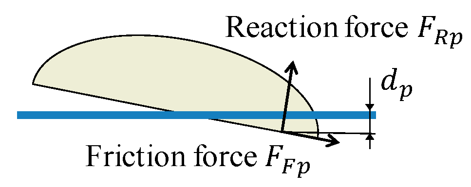
Figure 4 shows the forces acting on the board in the conventional simulation. The reaction force acting on the board is calculated using the penetration depth of the board into the snow surface. The vertical reaction force F R p and the frictional force F F p acting on a small element p of the board bottom are calculated using the following equation:
F R p = K Δ A p d p
F F p = μ b F R p
Here, K [(N/m) /m2] is the spring constant per unit area of the slope, Δ A p [m2] is the area of the small element p of the board, d p is the penetration depth of the small element p , and μ b is the friction coefficient between the board and the slope.

4. Test Equipment

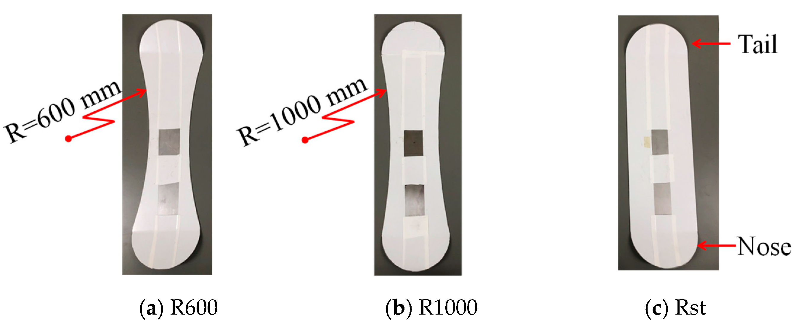
Figure 5 shows the test board. A weight was set on the board to reproduce the movement of its center of gravity as generated by a rider. The angle of the weight was set to be constant as the board underwent sliding motion. A six-axis motion sensor was placed at the center of the board to measure postures, and its coordinate axes were identical to those depicted in Figure 1. A black sphere was set atop the board to measure board position by using a stereo camera system. Figure 6 shows the three experimental boards made of stainless steel. The length and width of all three boards were 500 mm and 133 mm, respectively. The boards had different sidecut radii of 600 mm (R600), 1000 mm (R1000), and no sidecut (Rst). In addition, the noses and tails of all boards were bent upward by 15°. Table 1 lists the masses and the positions of the center of gravity of each board. To evaluate the effect of the sidecut radius, the boards were stiff such that they did not deform when running. Although stiffness is an important parameter on the snowboard, rigid boards were used to validate the interaction between the board and the DEM model.
The width, length, and angle of the test slope shown in Figure 7 were 1500 mm, 2700 mm, and 23°, respectively. The slope was covered with small plastic pipes to reproduce the discrete behavior of snow. The plastic pipes were used in order to test the validity of the simulation model. They imitate granular snow, which is dry and made of relatively bigger crystals than regular snow. The dimensions of these plastic pipes were as follows: internal diameter = 7 mm, length = 10 mm, and thickness = 0.5 mm. The origin of the X-Y coordinate system was set at the initial position of the boards. By using the stereo camera to detect the detection marker, the trajectory of the board was measured in terms of three-dimensional coordinates.

5. Test and Simulation Conditions

The simulations were performed under the same conditions as the test. The initial velocity of the boards was set to 0 m/s. The sliding tests were performed five times with each test board to compare the turn trajectories and board postures with the simulation results.
Although a few of the parameters could be derived from the material characteristics, the other parameters were difficult to derive. For this reason, we performed an identification test to determine the friction and damping coefficients to match the angle of repose with the corresponding value in the DEM simulation results, which is shown in Figure 8. At first, the pipes were piled in a container with a division plate. Then, the pipes were released by removing the division plate to create a slope. The angle of repose, which was the slope angle created by the falling pipes, was measured and reproduced in the DEM simulation. The simulation parameters were set to ensure that the simulated slope angle matched the test result. The parameters employed in the DEM simulation and the linear spring model simulation are listed in Table 1, Table 2 and Table 3, respectively.
Board Slope   μ b

6. Test Results and Simulation Results

6.1. Trajectory

Figure 9 shows the trajectories of the center of the board in the simulations and the test. The blue lines show the DEM simulation results, the green lines show the linear spring simulation results, the red lines show the average of validation test, and the 95% confidence intervals of the averaged trajectories in the tests are shown in the red area. In addition, the board center positions at 0.8 s are marked on each trajectory. The lengths and breadths of the rectangles indicate the 95% confidence intervals of the average value along the X- and Y-directions of the board center at 0.8 s.
Figure 9 indicates that board movement in the Y-direction increased in both the simulations and the test as the sidecut radius decreased. This tendency agrees with the snowboard turn mechanism described in Section 2. The trajectories of all boards in the DEM simulation were almost inside the confidence interval of the test. By contrast, the differences in trajectory between the linear spring model simulation and the test increased as the sidecut radius decreased. Therefore, the modeling of the slope surface with the DEM improved the accuracy of the trajectory prediction.
The board X-positions at 0.8 s in the DEM simulation results deviated from the confidence intervals of the test results, and the running velocities in the DEM were slower than the ones in the test. By contrast, the positions of the R1000 and Rst boards at 0.8 s in the linear spring model simulation results were within the 95% confidence interval range of the test results along the X-direction. The position of the R600 board at 0.8 s in the linear spring model simulation was closer to the 95% confidence interval than the DEM simulation result. Although the DEM simulation could predict turn trajectory, a scheme that is a re-identification of parameters related to the interaction between the board and the slope (e.g., static and dynamic friction coefficient, damping coefficient) is needed to improve its reproducibility of the running velocity of the board.

6.2. Board Postures

Figure 10 shows the maximum edge angles and attack angles. The test values are averages of the maximum values obtained in the five tests using each board. The edge angles and the attack angles increased as the sidecut radius of the boards decreased. Moreover, the sidecut radius also affected both edge angles and attack angles of the boards. The angles predicted in the two simulations exhibited almost the same tendency as the postures obtained in the test. Specifically, the DEM simulation results were closer to the test results than the linear spring model simulation results. The DEM can thus provide superior predictions of board posture during a turn.
In the DEM of the R1000 and the Rst boards, the edge and attack angles were equivalent. In contrast, the resulting turn trajectories of the two boards differed from each other, as shown in Figure 9. This difference was ascribed to the edges of the boards. The edge of the R1000 board penetrated the snow surface deeper than the one of the Rst, and the board turned while creating a curved groove on the slope. This groove constrained the sliding motion of the board. As a result, the movement of the R1000 in the Y-direction increased. This is consistent with the turn mechanism described in Section 2, and the DEM reproduced the influence of board shape on its turn trajectory.

7. Conclusions

A simulation model that represents snow with particle elements was developed to quantify the snowboarding performance of snowboard prototypes. We validated the effectiveness of the proposed DEM model by comparing it with the conventional model and the test. Moreover, the comparison revealed that the turn trajectories and postures reproduced by the DEM simulation were closer to the test results than those reproduced by the conventional linear spring model simulation. In the simulations performed by varying the sidecut radius, the DEM simulation provided superior predictions of board trajectory and posture than the conventional simulation.

Acknowledgments

This work was supported by JSPS KAKENHI Grant Number JP17K14614.

References

  1. Sakata, T.; Tsukiyama, M.; Hosokawa, K. Study on Simulation of Snowboard Turn. Mech. Eng. J. 1999, 65, 4431–4437. [Google Scholar] [CrossRef]
  2. Scott, N.; Yoneyama, T.; Kagawa, H.; Osada, K. Measurement of ski snow-pressure profiles. Sports Eng. 2007, 10, 145–156. [Google Scholar] [CrossRef]
  3. Petrone, N. The use of an Edge Load Profile static bench for the qualification of alpine skis. Procedia Eng. 2012, 34, 385–390. [Google Scholar] [CrossRef]
  4. Federolf, P.; JeanRichard, F.; Fauve, M.; Lüthi, A.; Rhyner, H.-U.; Dual, J. Deformation of snow during a carved ski turn. Cold Reg. Sci. Technol. 2006, 46, 69–77. [Google Scholar] [CrossRef]
  5. Mössner, M.; Heinrich, D.; Schindelwig, K.; Kaps, P.; Lugner, P.; Schmiedmayer, H.-B.; Schretter, H.; Nachbauer, W. Modeling of the Ski-Snow Contact for a Carved Turn. In The Engineering of Sport 6; Springer: New York, NY, USA, 2006; pp. 195–200. [Google Scholar]
  6. Abe, M.; Fujino, T.; Saito, F.; Takahata, K.; Iwamoto, K. Three-Dimensional Dynamic Simulation Analysis of Snow Removal Characteristics of Rotary Equipment. J. Syst. Des. Dyn. 2011, 5, 982–993. [Google Scholar] [CrossRef]
  7. Yoshida, T.; Hojo, A.; Kuratani, F. Simulation of snowboarding on snow surface modelled with particle elements. In Proceedings of the 6th International Congress on Sport Sciences Research and Technology Support, Seville, Spain, 20–21 September 2018; pp. 23–26. [Google Scholar]
  8. Fukumoto, Y.; Sakaguchi, H.; Murakami, A. The role of rolling friction in granular packing. Granul. Matter 2013, 15, 175–182. [Google Scholar] [CrossRef]
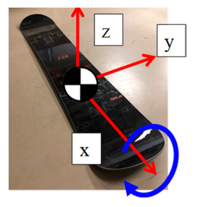
Figure 1. Coordinate system.
Proceedings 49 00101 g001
Figure 2. Mechanism of snowboard turn.
Proceedings 49 00101 g002
Figure 3. Model of snow with particle elements.
Proceedings 49 00101 g003
Figure 4. Linear spring model.
Proceedings 49 00101 g004
Figure 5. Experimental device.
Proceedings 49 00101 g005
Figure 6. Test boards.
Proceedings 49 00101 g006
Figure 7. Slope and stereo camera for the test.
Proceedings 49 00101 g007
Figure 8. Identification test for the distinct element method (DEM) parameters.
Proceedings 49 00101 g008
Figure 9. Results of trajectory.
Proceedings 49 00101 g009
Figure 10. Edge angles and attack angles in the experiment and the simulation.
Proceedings 49 00101 g010
Table 1. Board parameters.
Sidecut Radius R600R1000Rst
Mass (g)Weight 154
Board 419537603
Center of gravity (mm)x 0.20.2−1.1
y 11108.1
z 191816
Table 2. Parameters for DEM simulation.
Particle number22,821
Radius r (mm)7
Mass (g)0.11
Friction coefficientBoard–Particle Static   friction   μ b s 0.167
Dynamic   friction   μ b d 0.122
Particle Particle   μ t 0.12
Spring constant Normal   K n j (N/mm)8.91
Tan gential   K s j (N/mm)3.18
Rolling   friction   coefficient   μ r 28.6
Damping coefficient Normal     η n j (Ns/mm)1.90 × 10−3
Tan gential   η s j (Ns/mm)1.14 × 10−3
Table 3. Parameters for the linear spring model.
Spring constant K ((N/m)/m2)1.67 × 105
Board Slope   μ b 0.122
Publisher’s Note: MDPI stays neutral with regard to jurisdictional claims in published maps and institutional affiliations.