Proceeding Paper

Laboratory Analysis of a Piston-Actuated Pressure Reducing Valve under Low Flow Conditions †

Department of Engineering, University of Ferrara, Via Saragat 1, 44122 Ferrara, Italy
*
Author to whom correspondence should be addressed.
Presented at the 4th International Electronic Conference on Water Sciences, 13-29 November 2019; Available online: https://ecws-4.sciforum.net/.
Proceedings 2020, 48(1), 26; https://doi.org/10.3390/ECWS-4-06444
Published: 12 November 2019
(This article belongs to the Proceedings of The 4th International Electronic Conference on Water Sciences)

Abstract

:
Pressure reducing valves (PRVs) effectiveness for water distribution networks’ (WDNs’) optimal pressure management is proven, but problems and operational limitations have been highlighted by some recent studies. In this work, the functioning of a piston-actuated pressure reducing valve (PA-PRV), subjected to low flow regimes, is investigated by means of a laboratory test set. The results obtained highlight that the PA-PRV tends not to respect the imposed set-point value, and can present an unstable behaviour, characterised by significant pressure oscillations under some flow-rate conditions.

1. Introduction

Pressure reducing valves (PRVs) are often used for the management of complex water distribution networks (WDNs), aiming at regulating the pressure at the inlet point of districts in order to limit water losses. Among the different types of pressure reducing valves, the most common are diaphragm valves, in which the pressure regulating device operates in a transverse direction to the flow. Another type of pressure regulating valve, even though less frequently used, is the piston-actuated valve, in which the regulating device operates in a parallel direction to the flow. The pilot that regulates the downstream pressure control mechanism can be mechanical or electronically remotely controlled, even in real-time mode. In the literature, diaphragm pressure reducing valves have been extensively investigated, from the device modelling in combination with the eventual electronic control apparatus [1], to the optimisation of their location in the networks and their setting value [2]. The efficiency of the use of PRVs in reducing water losses has been proven in several studies [3]. However, the physical behaviour of PRVs has been investigated by a limited number of studies. In particular, Meniconi et al. [4] have characterised the behaviour of a diaphragm PRV through laboratory tests, both under steady and unsteady flow conditions, demonstrating the device versatility as an effective tool for the management of pressures. Other studies have instead highlighted some problems relating to the singular behaviours of these devices, which are not yet well understood. In more detail, some recent studies have shown the occurrence of instability in electronically controlled diaphragm PRVs under low flow regimes [1,5,6]. It is worth noting that all the studies here mentioned refer to diaphragm PRVs. Unlike these studies, this paper aims to characterise a piston-actuated PRV (hereinafter labelled as PA-PRV) with a mechanical pilot subjected to low flow regimes by means of laboratory tests. The main PA-PRV characteristics and the testbed are given below, and the tests conducted are then described. The results are analysed and compared with those reported in other studies and, finally, some concluding remarks are given.

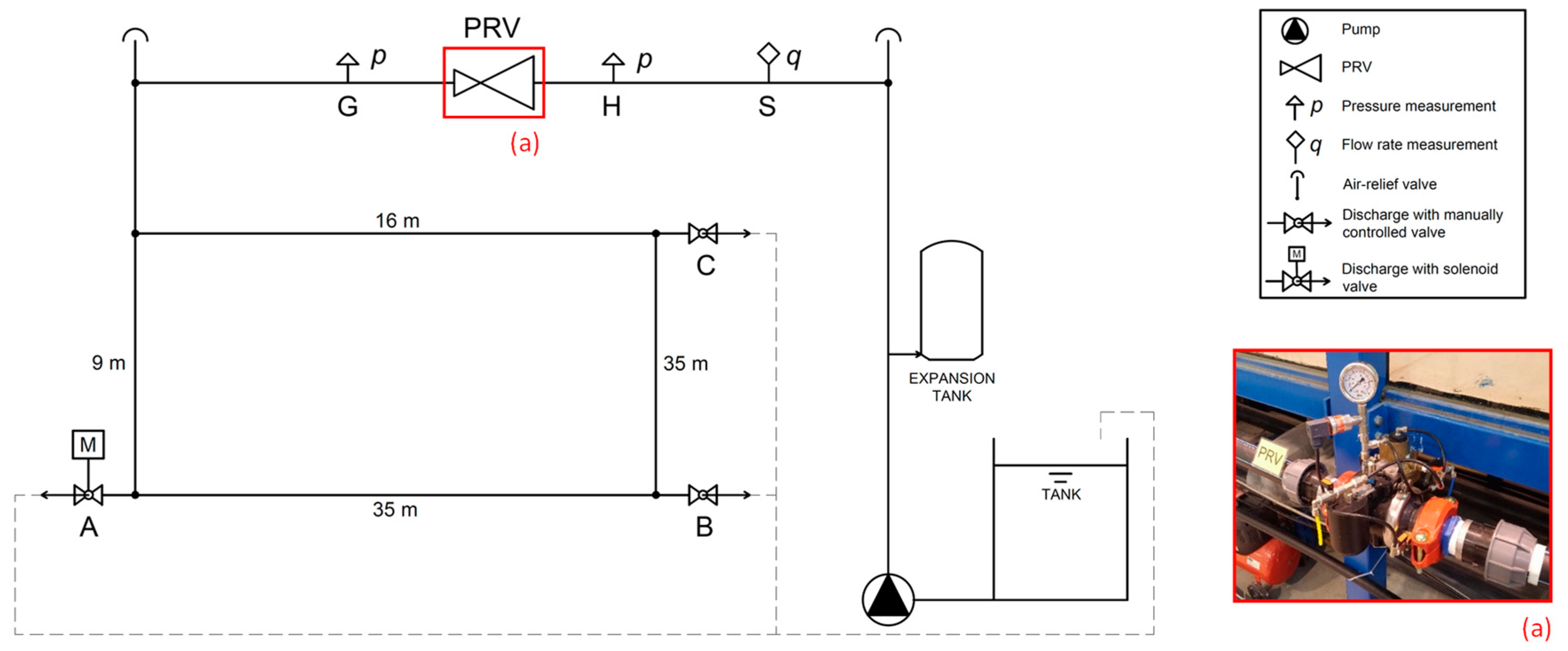
2. Materials and Methods
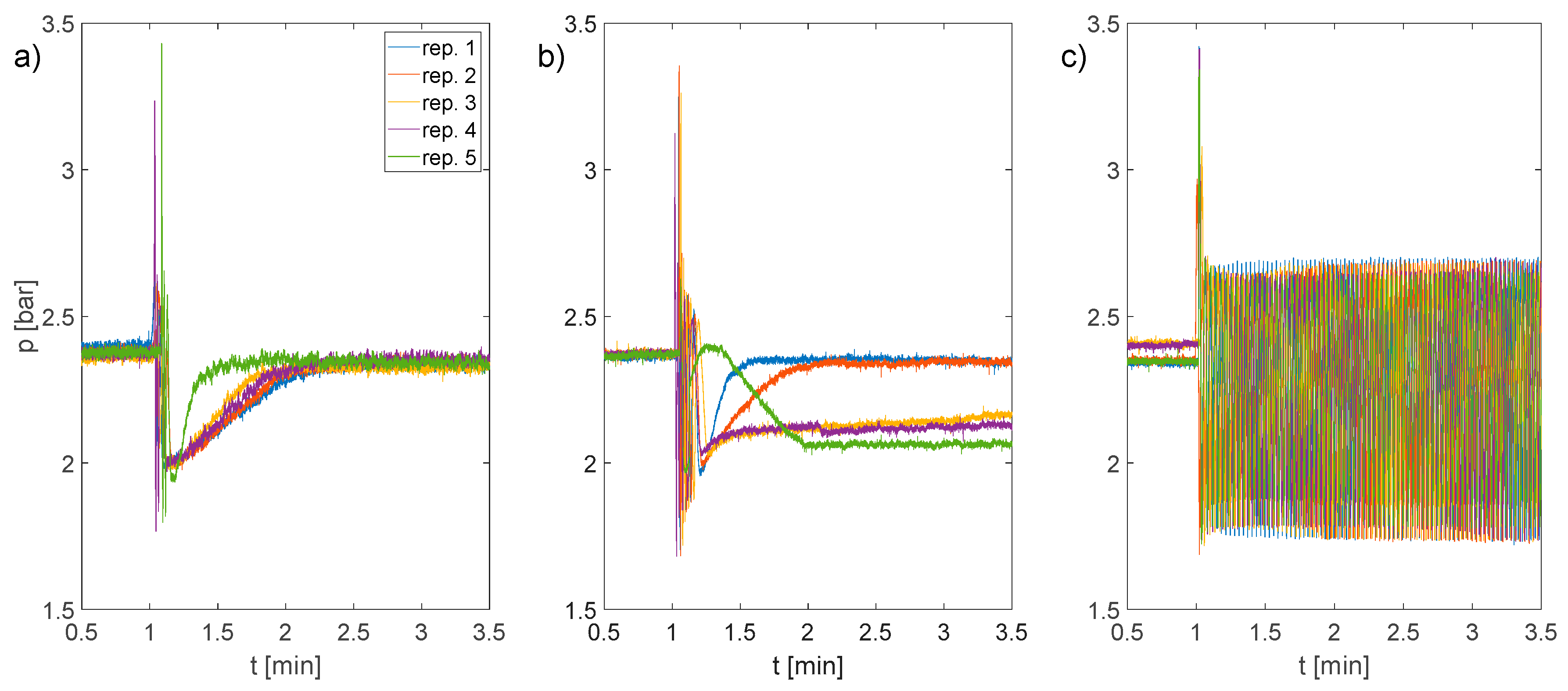
The PA-PRV analysed in this study consists of a plastic valve and an independent control unit formed by a pilot and a three-position selector of the C-valves type marketed by Saisanket Ltd [7]. The three-way pilot that controls the valve does not have a piston speed-adjustment manual regulation system, as the functioning of the device is based on the proprietary technology “Linear Flow Linear Control”. Operationally, the characterised PA-PRV has a nominal diameter DN of 50 mm. The operational range of the valve indicated by the producer is between 0 and 25 bar, and between 0 and 80 m3/h, and the tolerance with respect to the setting value of the downstream pressure is ±0.5 m. The behaviour of the PA-PRV has been investigated through a set of laboratory tests using the hydraulic system of the Hydraulic Laboratory of the Engineering Department of the University of Ferrara, whose scheme is illustrated in Figure 1. The hydraulic system is fed by a centrifugal pump, which provides, at the best efficiency point, a flow rate of about 1 L/s and a head of 52 m. The supply pipe consists of a polyethylene pipe with a diameter of 63 mm (PN 16) and a length of about 10 m, along which the PA-PRV, two pressure measurement sections upstream and downstream of the PA-PRV and an electromagnetic flowmeter (respectively sections H, G e S in Figure 1) are installed. The supply pipe is connected to a polyethylene loop with a diameter of 40 mm (PN 10), for a total length of about 100 m, characterised by the presence of three junctions indicated with letters A, B and C in Figure 1, where the discharge can be released towards the tank through three control valves. Opening a degree of the three control valves located at sections A, B and C allows the discharge outflowing from the loop towards the tank to be regulated, and consequently to regulate the discharge in the supply pipe flowing through the PA-PRV valve. In particular, a solenoid valve with a remotely controlled modular opening is installed at manoeuvring section A, while the discharge valves at sections B and C are manually controlled. During the tests, flow rate and pressure at strategic sections of the system, i.e., upstream and downstream of the PA-PRV at sections H and G, respectively, and at the manoeuvring section A, were monitored, with an acquisition frequency of 100 Hz.
The characterization of the PA-PRV was conducted through a set of tests aimed at verifying the ability of the PA-PRV to maintain an imposed set-point at the downstream section with respect to different flow rates. The set-point value is imposed equal to 2.4 bar, and the behaviour of the PA-PRV is analysed in the face of a variation of flow rate ∆Q within the system equal to 0.5 L/s starting from different initial flow rate values Qin. In particular, 9 initial flow rate values Qin between 1.4 L/s and 0.6 L/s, with a step of 0.1 L/s, and corresponding final flow rate values Qfin between 0.9 L/s and 0.1 L/s, were considered. In order to evaluate the variability of the behaviour of the PA-PRV with respect to the same boundary conditions, each test was repeated five times, and for each test the sampling of the pressures and flow rates was carried out for a duration of 6 min, 1 min before and 5 min after the reduction ∆Q of the circulating flow rate.

3. Results

The analysis of the laboratory tests highlights that the PA-PRV presents a correct behaviour, i.e., it is capable of maintaining the imposed pressure at the downstream section in the face of the flow rate variation ∆Q, when the final flow rate Qfin is higher than or equal to 0.7 L/s. As an example, the results of the test for Qfin = 0.8 L/s are reported in Figure 2a. The pressure signal observed downstream of the PA-PRV presents some marked oscillations, due to the flow rate reduction manoeuvre, but after that, the pressure tends to stabilise around the imposed set-point value. For the final flow rates Qfin lower than 0.7 L/s but higher than 0.2 L/s, an anomalous behaviour of the PA-PRV is observed. Indeed, in some cases, the PA-PRV tends to quickly stabilize on the set-point value, but in others it tends to reach the set-point value in extremely prolonged times, longer than the sampling time of 6 min, or to stabilise around smaller values, about 0.4 bar lower than the setting value. For the sake of brevity, the results of the test for Qfin = 0.5 L/s are shown in Figure 2b. This tendency to stabilise around two set-points can be interpreted given the work proposed by Dempster and Alshaikh [8]. The authors, in fact, by studying safety valves in the industrial environment subjected to determined flow conditions, show that their behaviour is influenced by the interaction between the force acting on the disc and the spring force, for which two different conditions of equilibrium are identified. In the light of this analysis, the behaviour of the PA-PRV, for flow rates lower than 0.7 L/s, could be influenced by the operation of the pilot valve which, like the safety valve analysed in the work of Dempster and Alshaikh [8], seems to have two distinct points of equilibrium that lead the PA-PRV to stabilize at different values of pressure. The difficulty of the PA-PRV to guarantee the value of downstream set-point is accentuated in tests with Qfin smaller or equal to 0.2 L/s reaching an important instability. Results in terms of pressure trend for Qfin = 0.2 L/s are reported in Figure 2c. As a result of the flow rate variation ∆Q, instability in the system is generated and pressure downstream of the PA-PRV starts to oscillate around an average value (smaller than the set-point), with an amplitude of 0.5 bar and a frequency of about 0.5 Hz.

4. Conclusions

This study investigates the behaviour of a PA-PRV under low flow conditions by means of laboratory tests. Three characteristic behaviour fields can be distinguished. The PA-PRV presents a correct functioning for flow rates higher than or equal to 0.7 L/s, maintaining the downstream pressure around the setting value; for flow rates between 0.7 L/s and 0.2 L/s, the PA-PRV tends to fail in maintaining the set-point value imposed, setting the downstream pressure around values lower than the set-point or showing extremely long stabilisation time intervals in order to reach the setting value. This behaviour can be related to an intrinsic difficulty of the pilot valve in finding a unique equilibrium configuration. Finally, a condition of persistent instability is observed for flow rates lower than or equal to 0.2 L/s.

Conflicts of Interest

The authors declare no conflict of interest.

References

  1. Janus, T.; Ulanicki, B. Hydraulic Modelling for Pressure Reducing Valve Controller Design Addressing Disturbance Rejection and Stability Properties. Procedia Eng. 2017, 186, 635–642. Available online: https://www.sciencedirect.com/science/article/pii/S1877705817314339 (accessed on 10 October 2019). [CrossRef]
  2. Giugni, M.; Fontana, N.; Ranucci, A. Optimal Location of PRVs and Turbines in Water Distribution Systems. J. Water Res. Plan. Manag. 2014, 140. Available online: https://ascelibrary.org/doi/abs/10.1061/%28ASCE%29WR.1943-5452.0000418 (accessed on 10 October 2019). [CrossRef]
  3. Fontana, N.; Giugni, M.; Glielmo, L.; Marini, G.; Verrilli, F. Real-Time Control of a PRV in Water Distribution Networks for Pressure Regulation: Theoretical Framework and Laboratory Experiments. J. Water Res. Plan. Manag. 2018, 144. Available online: https://ascelibrary.org/doi/10.1061/%28ASCE%29WR.1943-5452.0000855 (accessed on 10 October 2019). [CrossRef]
  4. Meniconi, S.; Brunone, B.; Mazzetti, E.; Laucelli, D.B.; Borta, G. Hydraulic characterization and transient response of pressure reducing valves: Laboratory experiments. J. Hydroinform. 2017, 19, 798–810. Available online: https://iwaponline.com/jh/article/19/6/798/37859/Hydraulic-characterization-and-transient-response (accessed on 10 October 2019). [CrossRef]
  5. Ulanicki, B.; Skworcow, P. Why PRVs Tends to Oscillate at Low Flows. Procedia Eng. 2014, 89, 378–385. Available online: https://www.sciencedirect.com/science/article/pii/S1877705814023170 (accessed on 10 October 2019). [CrossRef]
  6. Changklom, J.; Stoianov, I. Fault Detection and Diagnosis for Pressure Control Valves in Water Supply Networks. In Proceedings of the CCWI 2017, Sheffield, UK, 5–7 September 2017. [Google Scholar]
  7. Saisanketvalves. Available online: https://www.saisanketvalves.com (accessed on 10 October 2019).
  8. Dempster, W.; Alshaikh, M. An Investigation of the Two Phase Flow and Force Characteristics of a Safety Valve. Procedia Eng. 2015, 130, 77–86. Available online: https://www.sciencedirect.com/science/article/pii/S1877705815040618 (accessed on 10 October 2019). [CrossRef]
Figure 1. Layout of the testbed installed in the Hydraulic Laboratory of the University of Ferrara.
Proceedings 48 00026 g001
Figure 2. Pressure signals observed at the section downstream of the piston-actuated pressure reducing valve (PA-PRV) (section G) during the tests characterised by (a) Qfin = 0.8 L/s, (b) Qfin = 0.5 L/s and (c) Qfin = 0.2 L/s, each repeated five times.
Proceedings 48 00026 g002

