Proceeding Paper

Undervoltage Identification in Three Phase Induction Motor Using Low-Cost Piezoelectric Sensors and STFT Technique †

Department of Electrical Engineering, São Paulo State University (UNESP), Bauru 17033-360, Brazil
*
Author to whom correspondence should be addressed.
Presented at the 6th International Electronic Conference on Sensors and Applications, 15–30 November 2019; Available online: https://ecsa-6.sciforum.net/.
Proceedings 2020, 42(1), 72; https://doi.org/10.3390/ecsa-6-06644
Published: 14 November 2019

Abstract

:
Three-phase induction motors (IMs) are electrical machines used on a large scale in industrial applications because they are versatile, robust and low maintenance devices. However, IMs are significantly affected when fed by unbalanced voltages. Prolonged operation under voltage unbalance (VU) conditions degrades performance and shortens machine life by producing imbalances in stator currents that abnormally raise winding temperature. With the development of new technologies and research on non-destructive techniques (NDT) for fault diagnoses in IMs, it is relevant to obtain economically accessible, efficient and reliable sensors capable of acquiring signals that allow the identification of this type of failure. The objective of this study is to evaluate the application of low-cost piezoelectric sensors in the acquisition of acoustic emission (AE) signals and the identification of VU through the analysis of short-term Fourier transform (STFT) spectrograms. The piezoelectric sensor makes NDT feasible, as it is an affordable and inexpensive component. In addition, STFT allows time-frequency analyses of acoustic emission signals. In this NDT, two sensors were coupled on both sides of an induction motor frame. The AE signals obtained during the IM operation were processed and the resulting spectrograms were analyzed to identify the different VU levels. After comparing the AE signals for faulty conditions with the signals for the IM operating at balanced voltages, it was possible to obtain a desired identification that confirmed the successful application of low-cost piezoelectric sensors for VU condition detection in three-phase induction machines.

1. Introduction

Due to its easy adaptation to different applications, three-phase induction motors (TIMs) are widely used in industries. Today, about 70% of industrial processes are driven by TIMs [1]. Consequently, there is a high demand for continuous and reliable monitoring of their operational parameters. One such parameter is the supply voltage of the machine. Inside a manufacturing plant, many factors can interfere in power quality and produce unbalanced voltages. The voltage unbalance (VU) condition affects the operation of the machine and may cause permanent damage. When exposed to VU, TIMs present high currents in affected phases which produces torque oscillations, winding overheating, power loss and loud audible noise [2]. These oscillations can lead to deterioration of the mechanical parts of the induction motor, as well as insulation wearing in the stator windings.
In consequence, many studies have been carried out to evaluate the occurrence of faults in TIM [3,4,5]. Among then, the non-destructive techniques (NDTs) emerge as a successful alternative for this purpose. This kind of approach allows diagnosing faults in electrical machines without causing any damage to the equipment or need for maintenance downtime [6,7]. Therefore, non-destructive techniques applied to voltage unbalance diagnostics prove to be a useful tool, since this type of fault can be intermittent and requires continuous monitoring.
In this context, the main goal of this work is the application of low-cost piezoelectric sensor to identify phase undervoltage in TIM using acoustic emission (AE) analysis as a non-destructive technique. In order to achieve the proposed objective, two piezoelectric sensors were attached to a 1.5 hp TIM and different VU patterns were applied to the machine. The AE signals acquired by the sensors were processed using short-time Fourier transform (STFT) and the resulting spectrograms were analyzed.
The experimental results indicate a good performance of the low-cost piezoelectric sensors. Once the STFT was applied to the AE signals, it was possible to identify different levels of VU present in the machine power supply. The satisfactory results ratify the capability of the proposed low-cost sensors to identify electrical supply faults in TIM trough the AE signals analysis.
On the following sections, the piezoelectric sensors and the STFT technique are presented in Section 2 and Section 3, respectively. The materials and methods proposed to this work experiments are described in Section 4 and the results in Section 5. The final thoughts and conclusions are addressed in Section 6.

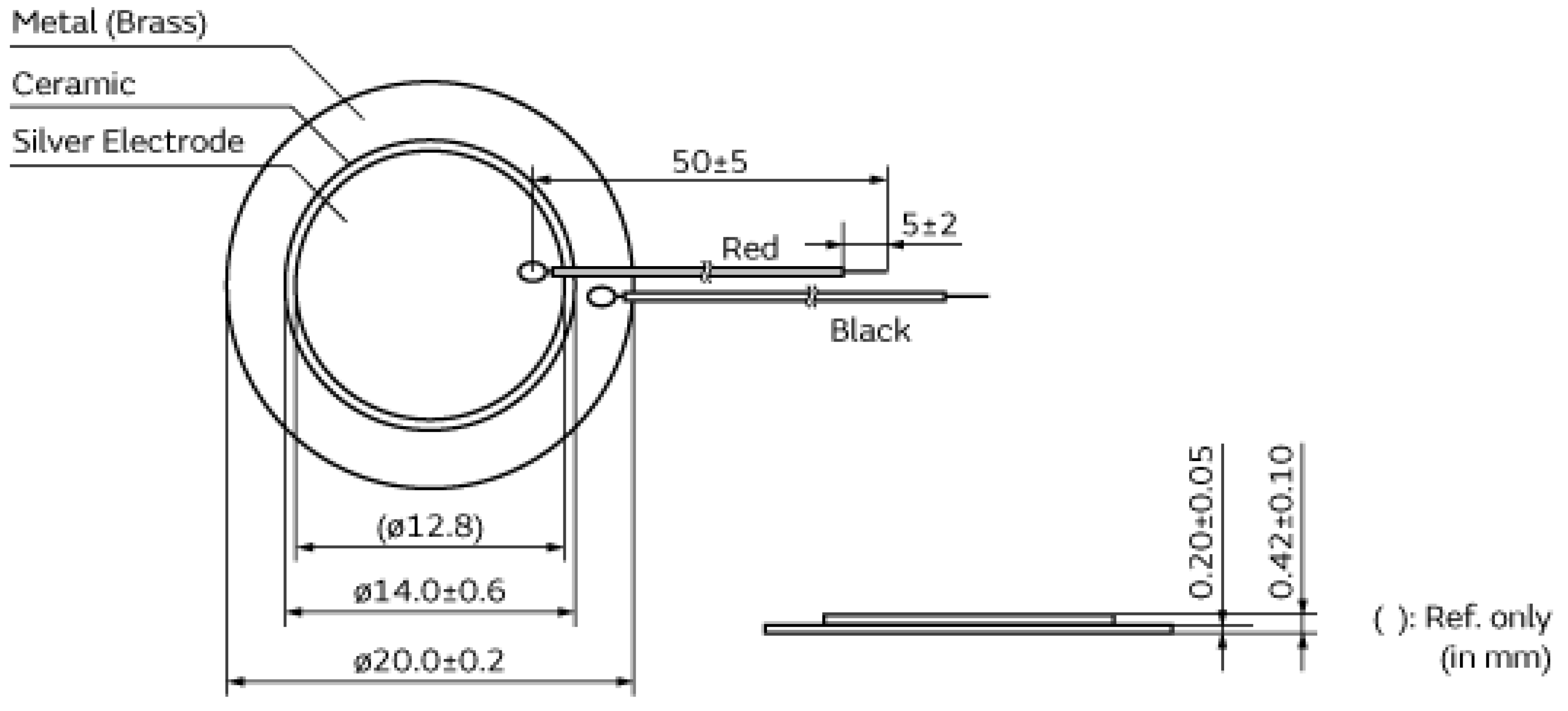
2. Piezoelectric Sensors

The proposed low-cost sensor is based on the piezoelectric effect. This phenomenon can be defined as a bi-directional relation between mechanical stress and electric voltage. The relation observed in the piezoelectric sensors is described as follows [8]:
D i = d i k l T k l + ε i k T E k
S i j = s i j k l E T k l + d k i j E k
The sensors used in this research were the piezoelectric diaphragms, which are similar to PZT ceramics. Also called buzzers, these components were generally applied as sound generators, however, many recent studies have used them as an AE sensor successfully [9,10]. These diaphragms have a circular brass plate with a diameter of 20 mm that houses a circular piezoelectric ceramic with a diameter of 14 mm, which is coated by a metallic film for electrical contact (Figure 1).
The acoustic emission signals are processed and analyzed by means of the short-time Fourier transform technique for identification of unbalanced voltages.

3. Short-Time Fourier Transform

The STFT is a time-frequency domain analysis that has been used several times in diagnostics of electrical machines [12,13]. It allows to evaluate the behavior of the frequencies of a signal over a certain period of time by dividing the signal into multiple small-time windows. The application of the STFT allows the compilation of a spectrogram. The Equation 1 shows the discrete version of STFT as follows [14]:
X ( k ) = n = 0 N 1 x ( n ) W N w k
where N is the number of samples, k is the discrete-frequency index, n is the discrete time index and W N n k corresponds to the transformation kernel as:
W N n k = e ( j ( 2 π k n / N ) )
The resulting spectrograms allowed to achieve the scope of this paper and the results were discussed in Section 5.

4. Materials and Methods

The procedures for the acquisition of AE signals and the physical assembly of electrical machines are described in this section, as well as the signal processing technique. Figure 2 presents the complete diagram of the proposed steps.

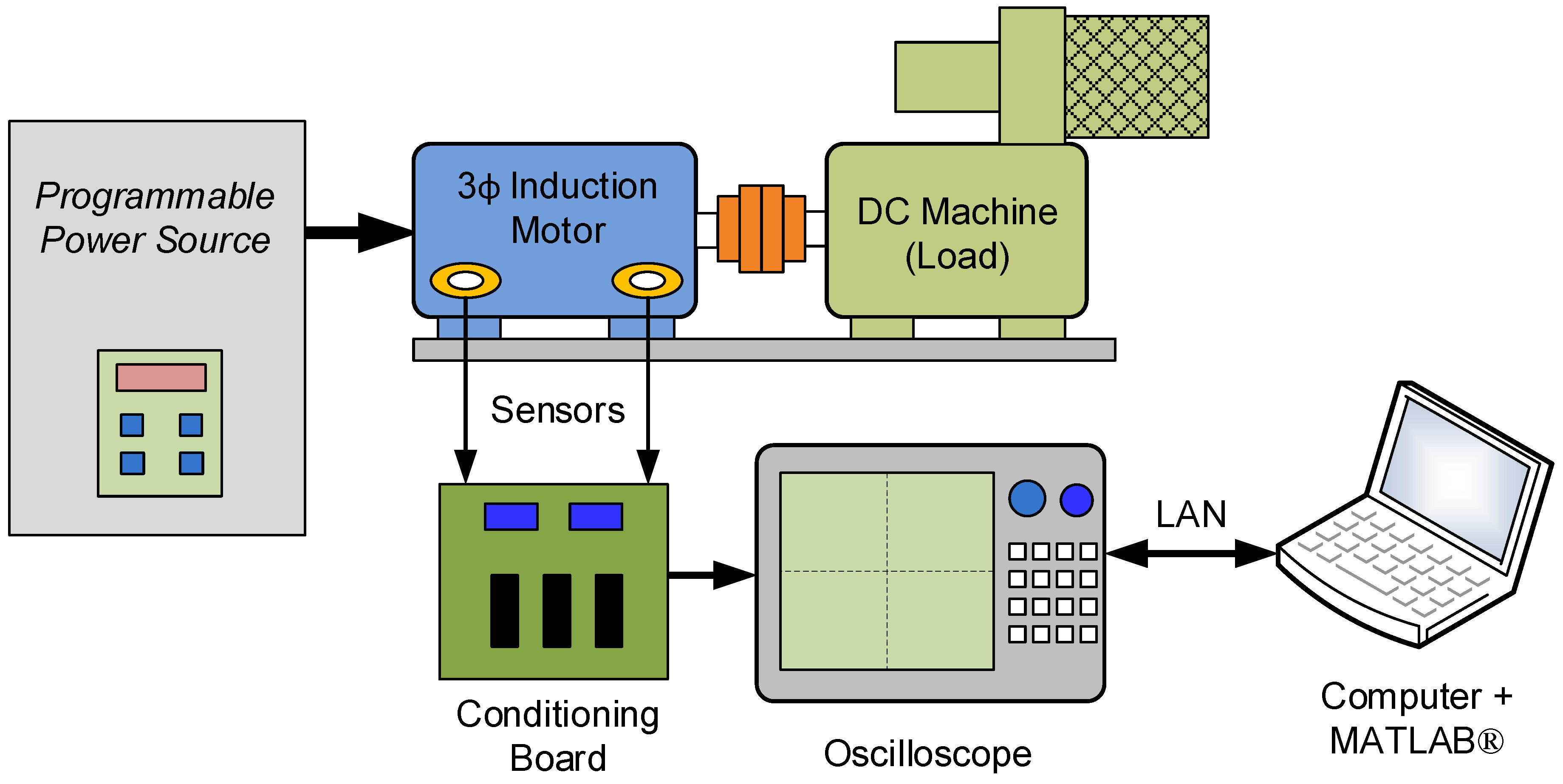
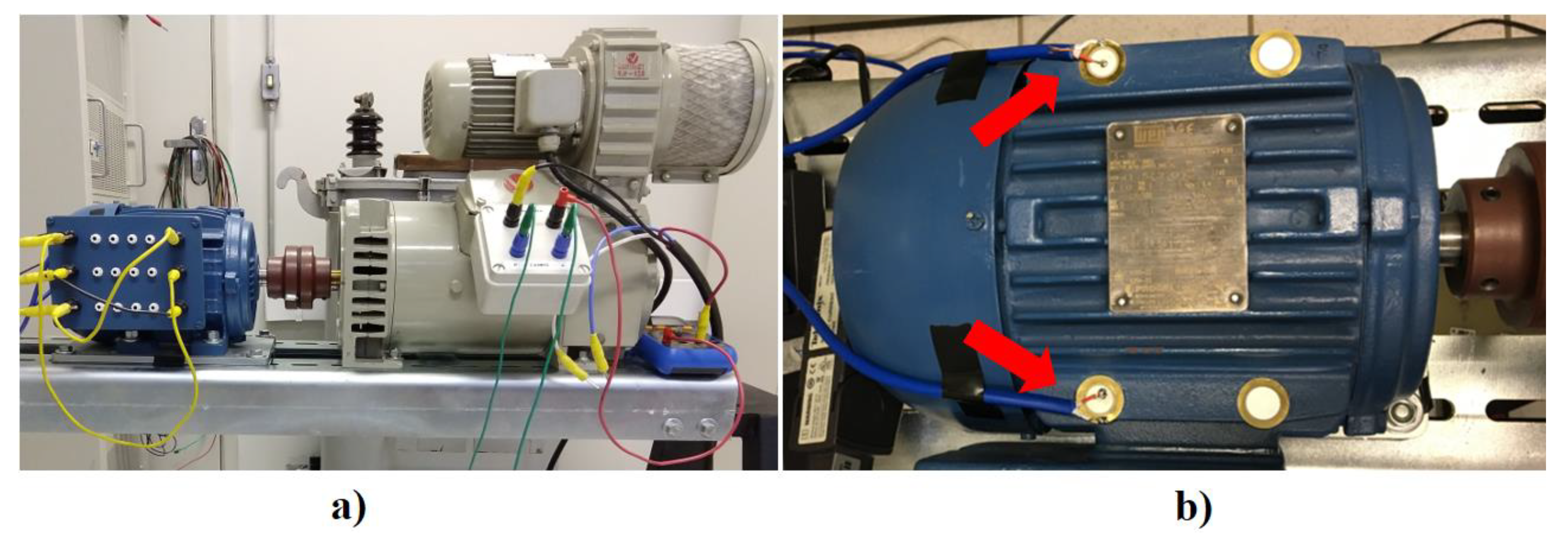
4.1. Machinery Setup

Initially, the 1.5 hp TIM was coupled to a DC machine and both of them were aligned and firmly bolted to the test bench (Figure 3a). The induction motor is powered by a Pacific Power 360 AMX three-phase programmable source that permits to program asymmetries and disturbances on their three-phase power output. The armature current of the DC machine was increased until the TIM current reached its nominal value. In this way, the load torque was applied on the motor shaft to simulate the real operational condition. After that, different levels of unbalanced voltages were applied to the TIM phases using the software-controlled three-phase source. The voltage values were presented in Table 1.

4.2. Sensor and Data Acquisition

In order to accomplish the signal acquisition, two low-cost piezoelectric sensors were attached to the TIM frame (Figure 3b). The acquired signals were conditioned by a board based on Texas Instruments® instrumentation amplifier IC INA 128P, whose frequency response is up to 400 kHz. After the conditioning, the signals were acquired by a digital oscilloscope. The sample rate was set to 2 MS/s, which satisfies the Nyquist theorem. Finally, the data were transferred to a personal computer where the STFT technique was accomplished and the results were analyzed using the software MATLAB®.

5. Results

Aiming to identify VU condition in TIM supply, the STFT values were calculated for each of the six undervoltage levels. Therefore, it was possible to draw one spectrogram for each of these levels. The AE signals were acquired for 2 s and the frequency axis was limited between 0 and 1.5 kHz, for better visualization. Also, the unbalanced voltages were applied after 1 s after the beginning of signal acquisition, thus, it is possible to evaluate the STFT values after and before the fault in the same image (Figure 4).
After the STFT application, the results showed that some frequencies presented a power increase directly proportional to the fault level. As consequence of VU, the power of 600–800 Hz frequency band of the AE signals has a significant increase as seen in Figure 4. Therefore, by evaluating the AE signals provided by the piezoelectric sensors through a spectrogram and comparing the power contained in this frequency range with its baseline value, this method allowed to identify the unbalanced voltages applied to the TIM.
The spectrograms presented in this section were accomplished using the signals obtained exclusively from just one sensor, after the application of the unbalanced voltages in phase A. However, the results achieved for the other phases and sensors also showed equivalent results.

6. Conclusions

Three-phase induction motors are often exposed to unbalanced voltages during their operation. This harmful condition has many origins and increases the electrical and mechanical wearing. As the VU can be a temporary occurrence, devices that are able to discern between faulty and normal operation present relevant advantages. In this framework, the NDT-based solutions allied with low-cost piezoelectric sensors stand out as a feasible alternative to industrial applications to identify VU faults in TIMs.
The results provided by the experiments pointed to the success of the AE signals analysis in identifying different levels of undervoltage faults. Consequently, the low-cost piezoelectric sensors proved to be satisfactory to this application. After the implementation of STFT, the resulting spectrograms showed a clear difference between the baseline values and the fault values.
Additionally, future works may be proposed through advanced signal processing techniques in order to classify the VU level. Finally, new approaches may also be able to identify which phases have been affected by unbalanced voltages.

Author Contributions

All authors contributed in writing, proofreading and providing suggestions for the improvement of the paper.

Conflicts of Interest

The authors declare no conflict of interest.

References

  1. Li, C.; Xu, D.; Wang, G. High efficiency remanufacturing of induction motors with interior permanent-magnet rotors and synchronous-reluctance rotors. In Proceedings of the 2017 IEEE Transportation Electrification Conference and Expo, Asia-Pacific (ITEC Asia-Pacific), Harbin, China, 7–10 August 2017; pp. 1–6. [Google Scholar]
  2. Campbell, M.; Arce, G. Effect of Motor Voltage Unbalance on Motor Vibration: Test and Evaluation. IEEE Trans. Ind. Appl. 2018, 54, 905–911. [Google Scholar] [CrossRef]
  3. Guerra de Araujo Cruz, A.; Delgado Gomes, R.; Antonio Belo, F.; Cavalcante Lima Filho, A. A Hybrid System Based on Fuzzy Logic to Failure Diagnosis in Induction Motors. IEEE Lat. Am. Trans. 2017, 15, 1480–1489. [Google Scholar] [CrossRef]
  4. Yu, Y.; Zhao, Y.; Wang, B.; Huang, X.; Xu, D. Current Sensor Fault Diagnosis and Tolerant Control for VSI-Based Induction Motor Drives. IEEE Trans. Power Electron. 2018, 33, 4238–4248. [Google Scholar] [CrossRef]
  5. Naha, A.; Thammayyabbabu, K.R.; Samanta, A.K.; Routray, A.; Deb, A.K. Mobile Application to Detect Induction Motor Faults. IEEE Embed. Syst. Lett. 2017, 9, 117–120. [Google Scholar] [CrossRef]
  6. Abd-el-Malek, M.; Abdelsalam, A.K.; Hassan, O.E. Induction motor broken rotor bar fault location detection through envelope analysis of start-up current using Hilbert transform. Mech. Syst. Sig. Process. 2017, 93, 332–350. [Google Scholar] [CrossRef]
  7. Jiang, C.; Li, S.; Habetler, T.G. A review of condition monitoring of induction motors based on stray flux. In Proceedings of the 2017 IEEE Energy Conversion Congress and Exposition (ECCE), Cincinnati, OH, USA, 1–5 October 2017; pp. 5424–5430. [Google Scholar]
  8. Moheimani, S.O.R.; Fleming, A.J. Piezoelectric Transducers for Vibration Control and Damping; Advances in Industrial Control; Springer: London, UK, 2006; ISBN 978-1-84628-331-4. [Google Scholar]
  9. Lucas, G.B.; de Castro, B.A.; Rocha, M.A.; Andreoli, A.L. Study of a Low-Cost Piezoelectric Sensor for Three Phase Induction Motor Load Estimation. Proceedings 2019, 4, 46. [Google Scholar]
  10. Barusu, M.R.; Sethurajan, U.; Deivasigamani, M. Non-invasive method for rotor bar fault diagnosis in three-phase squirrel cage induction motor with advanced signal processing technique. J. Eng. 2019, 2019, 4415–4419. [Google Scholar] [CrossRef]
  11. MURATA—Piezoelectric Sound Components Catalog. Available online: https://www.murata.com/en-us/products/productdata/8796782788638/E84G0211.gif?1473046207000 (accessed on 14 October 2019).
  12. Benkedjouh, T.; Zerhouni, N.; Rechak, S. Deep Learning for Fault Diagnosis based on short-time Fourier transform. In Proceedings of the 2018 International Conference on Smart Communications in Network Technologies (SaCoNeT), El Oued, Algeria, 27–31 October 2018; pp. 288–293. [Google Scholar]
  13. Ojeda-Aguirre, N.A.; Martinez, D.C.; Garcia-Perez, A.; Troncoso, R.J.R.; Valtierra-Rodriguez, M.; Amezquita-Sanchez, J.P. Reassignment technique for detection of broken rotor bar fault in induction motors. In Proceedings of the 2017 IEEE International Autumn Meeting on Power, Electronics and Computing (ROPEC), Ixtapa, Mexico, 8–10 November 2017; pp. 1–6. [Google Scholar]
  14. Bossio, G.R.; De Angelo, C.H.; Donolo, P.D.; Castellino, A.M.; Garcia, G.O. Effects of voltage unbalance on IM power, torque and vibrations. In Proceedings of the 2009 IEEE International Symposium on Diagnostics for Electric Machines, Power Electronics and Drives, Cargaese, France, 31 August–3 September 2009; pp. 1–6. [Google Scholar]
Figure 1. Piezoelectric sensor [11].
Proceedings 42 00072 g001
Figure 2. Setup diagram.
Proceedings 42 00072 g002
Figure 3. (a) Three-Phase induction motor (TIM) coupled to a DC machine; (b) piezoelectric sensors attached to TIM.
Proceedings 42 00072 g003
Figure 4. Short-term Fourier transform (STFT) spectrograms.
Proceedings 42 00072 g004
Table 1. Undervoltage values.
VF/VN 1 [%]VAN RMS
Voltage [V]
VAB RMS
Voltage [V]
VBC RMS
Voltage [V]
VCA RMS
Voltage [V]
00127220127
2025,4141.4220141.4
4050.8158.6220158.6
6076.2177.8220177.8
80101.6198.4220198.4
1 VN is the nominal phase voltage and VF is the fault phase voltage.
Publisher’s Note: MDPI stays neutral with regard to jurisdictional claims in published maps and institutional affiliations.

