1. Introduction
The Linear Fresnel Reflector (LFR) solar thermal system is a promising technology in solar thermal applications that has attracted significant attention recently, especially for small-scale use with heat output in the range of 150–300 °C [
1]. It is arranged in several long rows of flat or slightly concave mirrors that focus the sunlight onto a fixed elevated tubular receiver running parallel to the reflector rotational axis. Mirror segments are aligned horizontally and track the sun such that the receiver is illuminated without needing to be moved. The heat transfer fluid (HTF) inside the receiver is heated up to a reference temperature, then directly used to run a thermodynamic power cycle to heat another working fluid through a heat exchanger. A sun tracking system is provided to allow the mirror segments to rotate around an axis parallel to the receiver. The accuracy of the solar tracker is a key parameter to maximize the solar collector efficiency.
Several solar controlling and tracking systems of LFR have been developed that can be classified according to their degrees of freedom and/or control system strategy. Regarding the degrees of freedom, there are two main types of tracking systems: single-axis trackers and dual-axis trackers. LFR systems are usually installed with one-axis tracking [
2,
3,
4,
5]; however, recently, a two-axis tracking system has been used to improve the optical efficiency of LFR systems [
6,
7]. Regarding the control strategy, there are two main types, open-loop [
6,
7,
8] and closed-loop controlled trackers [
5,
9,
10]. In an open-loop tracking system, mathematical calculations of the sun position are applied without any feedback signal. In [
4], an open-loop control tracking system is proposed, consisting of a microcontroller board, Arduino UNO, and one stepper motor for all mirror rows, which were connected by a sprocket–roller chain system. In [
8], a tracking system of 50 lines of LFR mirrors was achieved using the concept of a parallelogram linkage mechanism (a double crank mechanism), whereby the motion transmitted to a single tube by a gear mechanism is transmitted equally to all the other tubes. The gears are rotated at a rate of 150 per hour by a small motor. In closed-loop tracking systems, feedback signals from sensors are used to determine how to drive the actuators and position the tracker structure. Few closed-loop control methods are applied.
The system described in [
2] used an electric motor for each of 10 mirror rows, while the optical model was used to calculate the tilt angle for each row. The authors of [
3] proposed a mechanical system for the tracking system, using a sprocket and chain drive transmission mechanism driven by a stepper motor for each mirror row. An encoder and a limit switch were used for determining the rotational position of each row.
In [
5], the tracking system of 10 lines of LFR mirrors is composed of 10 parallel lever arms, one for each line, connected by an actuator bar. The projected mechanism can rotate the mirror lines by 80°, thus tracking the sun almost the entire day, from −80° to 80°. A PWM speed controller was used to decrease even further the speed of the actuator, thereby increasing the position controllability accuracy. The tracking mechanism uses only one motor to move all mirror lines, with one inclinometer installed at the second line of the collector. The system described in [
9] proposed a tracking system of 11 lines of LFR mirrors divided into two rows, using a drive actuator for each mirrors’ row to move independently of the adjacent ones. Each mirror row is equipped with a potentiometer to determine the current position of the mirrors. In [
10], each mirror row is equipped with a potentiometer to provide a feedback measure of the actual position of the mirror rows during operation, with an accuracy of 0.1°.
From the literature review, it is clear that the solar tracking systems applied for the LFR use only one accelerometer, either for the whole plant or for each row, for providing a feedback signal about the real position of mirrors. This means that, in case of a problem such as wear and tear in the tracking system mechanism, erroneous angular readings are detected and result in inaccurate tracking of the sun position.
This paper describes a methodology to improve the tracking accuracy of the LFR. The proposed system involves using multiple accelerometers for each row of LFR instead of one, providing a more robust angular reading. Moreover, the collected data are transmitted over a wireless sensor network. This is a relatively simple and cheap system as the price of the accelerometer in this paper is about 5 EUR.
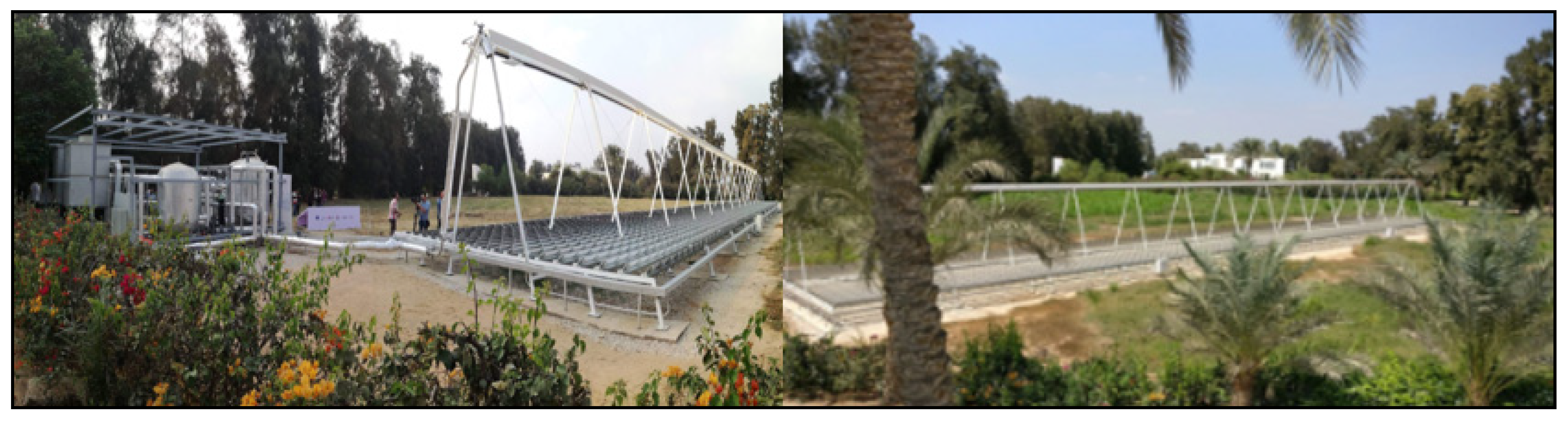
The proposed LFR is installed in SEKEM Medical Center near Belbeis, Egypt. This is a multi-generation solar plant that consists of an LFR solar collector, a thermocline storage tank, an Organic Rankine Cycle (ORC) and a Thermally Driven Chiller (TDC), as shown in
Figure 1. The solar field consists of 13 modules with a total area of 296 m
2; one basic IFC-1832 solar collector module has a total approximate length of 4 m and 18 rows of mirrors, each 0.32 m wide [
11]. Each mirror is produced with a specific curvature to focus the reflected beams into the absorber tube.
2. Materials and Methods
To verify the proposed system and the accelerometers’ performance in a real environment, a small WSN network consisting of a gateway and four nodes was deployed on the PV panel. Each node consists of an Arduino Uno (Torino, Italy) with the XBee module and a three-axis accelerometer, as shown in
Figure 2. Two different low-power accelerometers have been used:
FXLN8361: low power consumption with high-precision three-axis acceleration sensor that measures the acceleration during the object’s motion with an optional sensitivity of ±2 g/8 g.
LIS2DH: ultra-low-power, high-performance three-axis accelerometer, which is based on MEMS. The module is fitted with a Gravity I2C interface with an optional sensitivity of ±2 g/±4 g/±8 g/±16 g.
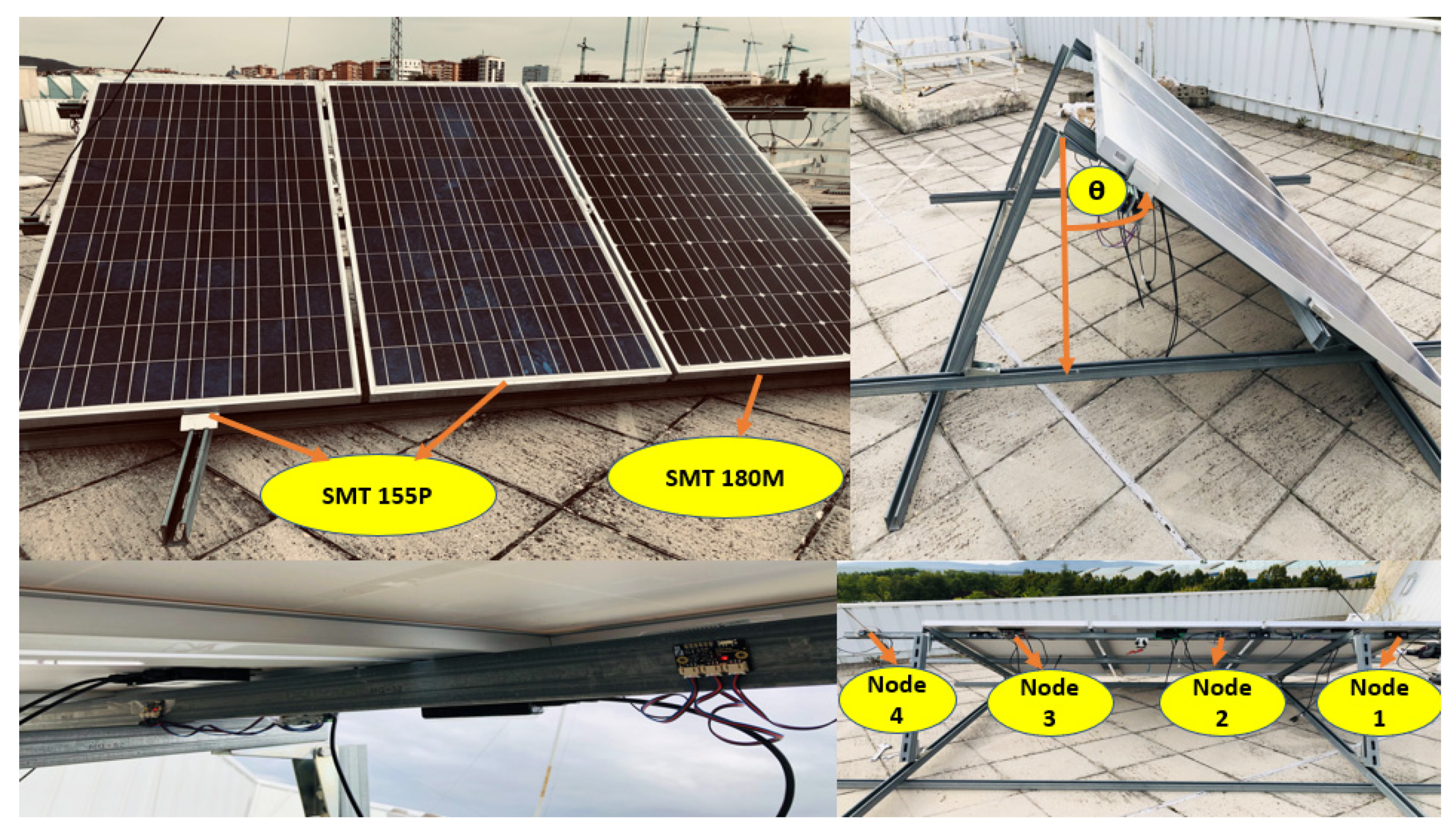
The first step is to test our methodology on a photovoltaic (PV) panel installed on a roof at the JdA building of the Public University of Navarre (UPNA). It has a similar structure to the LFR, consisting of one moving structure for three PV panels from Romag, as seen in
Figure 3. One is made with monocrystalline silicon technology (model SMT 180M (5165)), with a peak power of 170 W, and the other two are polycrystalline (model SMT 155P), with peak power of 155 W. The accelerometers are distributed on the PV panel structure, where nodes 1 and 2 are connected to LIS2DH accelerometers and nodes 3 and 4 are connected to FXLN8361 accelerometers, which are located on the backside of the PV panels.
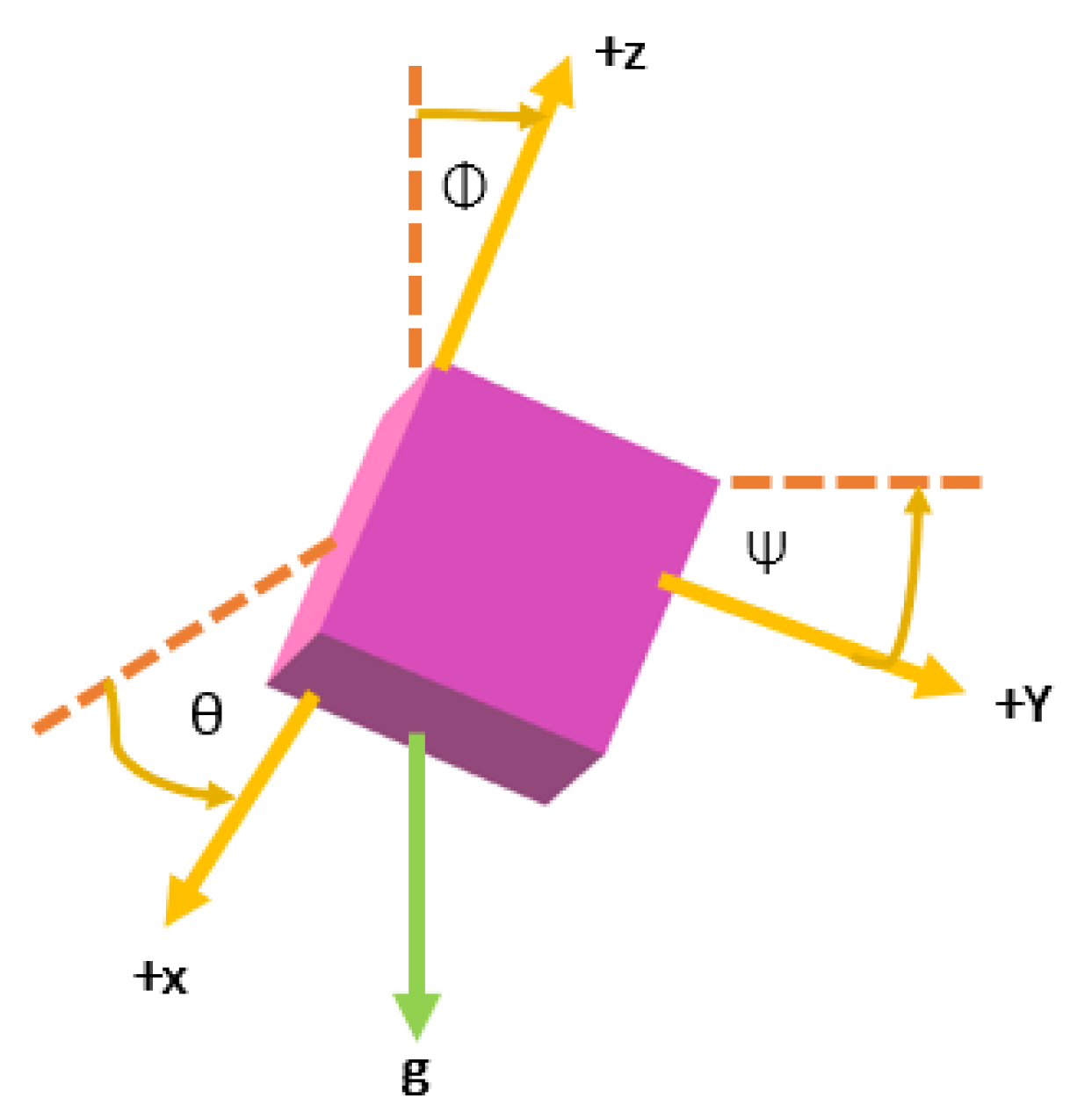
The three-axis accelerometer contains three analog outputs for X, Y, and Z axis accelerations, which are converted into angles in relation to each axis. The output voltages are connected to the analog inputs of Arduino UNO to be measured. Tilt angle measurement requires initial calibration, based on the gravity effect for each accelerometer. The tilt angles are given by:
where θ is the angle between the horizon and the
x-axis of the accelerometer, ψ is the angle between the horizon and the
y-axis of the accelerometer, and φ is the angle between the gravity vector and the
z-axis, as shown schematically in
Figure 4. The tilt angle data from all the nodes are sent via a wireless sensor network to the communication gateway, in order to enable further processing and angle data verification.
4. Discussion
Most of the solar tracking systems at an LFR plant use one feedback signal of the current position for the whole plant or for each row, which can provide an inaccurate position for the control system. This paper describes a system that can be used to supervise the tracking system of solar collectors with long mirror structures, by means of distributed tilt angle measurement devices that are easy to implement and involve low energy consumption and low cost. The proposed system employs an XBee ZigBee wireless sensor network to transmit the measured tilt angles, using accelerometers, to a monitoring server at a remote location. Thus, in case of misalignment, it is possible to take the average value of the distributed angle measurement data to increase the efficiency of the plant. Moreover, the proposed system can also aid in fault detection of the mirror mechanical systems, enabling flexible alarm transmission.
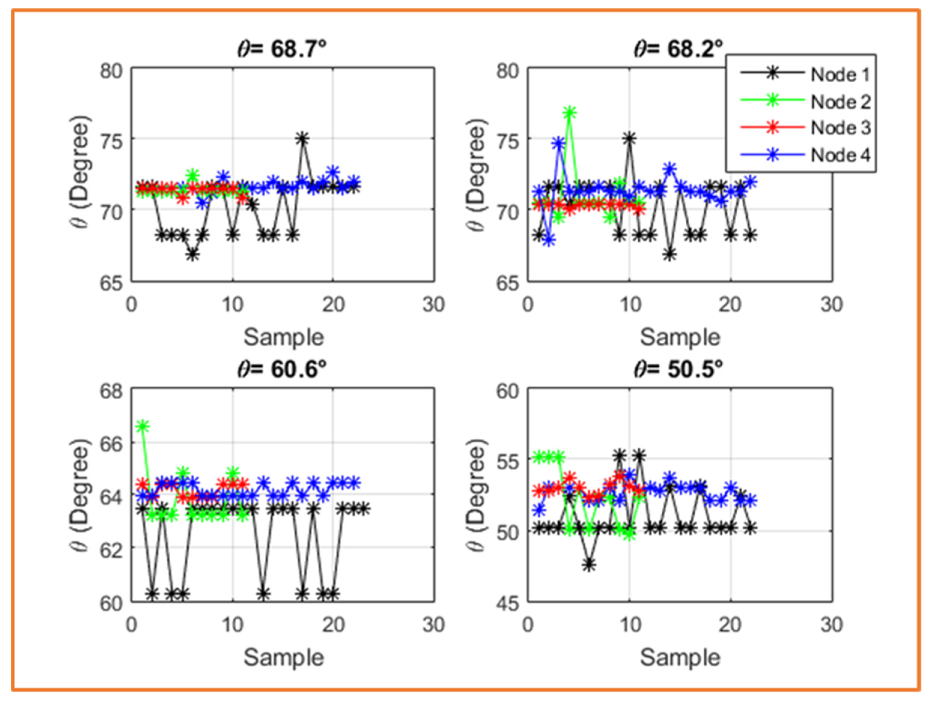
Several experimental tests were performed at different inclination angles. The experiment shows that data collected from FXLN8361 accelerometers are better than data from LIS2DH accelerometers. However, the mean value for a number of samples must be calculated to cancel the effect of the presented noise. Moreover, the node with the larger sampling time was less affected by noise. This was an important step in the development of WSN accelerometers that will be applied on all rows of a linear Fresnel concentrator plant.


 ,
, 


