Abstract
Wind energy is one of the most promising forms of renewable energy. For the constant evolution of power generation technology, the use of sensors is fundamental to the development of wind turbine emulators. A wind turbine emulator allows tests and evaluations of a wind power system, regardless of weather conditions. Therefore, to further improve this technology, this work focuses on the application of a torque transducer and a rotary encoder for the implementation of a closed-loop wind turbine emulator. The sensors provide the torque and speed feedback signals to the computational model so that the model could plot the power curves and produce the set point voltage used by a variable-frequency drive (VFD) to control a three-phase induction motor (TIM). The emulator was implemented using a control algorithm designed on LabVIEW, with an NI 6211 for the data acquisition. Finally, the system emulates the behaviour of a wind turbine, considering the variations in wind speed, aerodynamic phenomena, load effects, and pitch angle. Experimental results demonstrated the effectiveness of using the TIM-VFD assembly for emulating a wind turbine since the wind turbine emulator behaved like a wind turbine in real-time.
1. Introduction
The increasing demand for electrical energy, driven by the development of the world economy, requires new energy strategies for competitiveness in modern markets. Conventional energy sources such as oil, coal, and natural gas present significant financial risks as they have constant price fluctuations. In addition, there is a steady increase in worldwide concern about global warming and climate change, caused by the increase in carbon dioxide emissions. On the other hand, the development of renewable energy sources stands out as an alternative to mitigate the setbacks of conventional power generation [1,2,3,4].
The expansion of wind power generation has led to a significant increase in wind energy conversion systems (WECS) research. As the wind is a stochastic variable, the experimental studies regarding WECS are not always feasible. Thus, wind turbine emulators (WTE) become essential for the technological development of the area, once they are independent of the intermittent nature of the wind. In addition, WTEs are capable of reproducing the same aerodynamic behaviour of real wind turbines [5,6,7].
However, to implement a closed-loop emulator, it is necessary to have feedback on some operational values. To accomplish that, the application of transducers to provide data from the test bench to the computational model is essential. Therefore, the focus of this paper is to apply a torque transducer and a rotary encoder for signal acquisition, with the aim of developing a hardware-in-the-loop WTE.
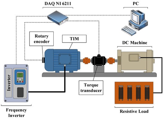
In order to achieve the proposed scope, the test bench was assembled using a three-phase induction motor (TIM) driven by a variable-frequency drive (VFD). A DC generator was coupled to the TIM and connected to a resistive load, in order to apply different torque levels. To measure the angular speed and torque levels, we used a rotary encoder and a torque meter. All the aerodynamic characteristics of a real wind turbine were considered in the LabVIEW model. Finally, a DAQ NI 6211 was used to acquire the signal provided by the two sensors and to set the control signal for the VFD.
The results showed that the proposed WTE was able to provide precise and exact values for the torque and power curves, matching a real wind turbine. There are seven sections in this work. Section 2 presents the aerodynamic model of the wind turbine. Section 3 outlines the use of the torque transducer. In Section 4, the rotary encoder is detailed. Section 5 is dedicated to materials and methods. The results are discussed in Section 6. Finally, the conclusions about this work are presented in Section 7.
2. Aerodynamic Model
The principle of working a wind turbine is based on aerodynamics. The turbine’s aerodynamic output power is given as [8,9]
where v is the velocity of air, is the power coefficient, ρ is the air density, and A is the area swept by the rotor blades. The conversion efficiency, or , is the ratio of available wind energy to the turbine shaft’s mechanical energy. It is a function of the tip speed ratio (λ) and pitch angle (β), which is given as
where is the tangential velocity, v is the velocity of air, and ωT in (rad/s) is the rotor angular velocity. The conversion efficiency, or (λ,β ), is given as
with given as:
The coefficients are given as [10] (Table 1):

Table 1.
Empiric coefficients for aerodynamic model.
The mechanical torque of a wind turbine is given by the ratio between the mechanical power and the angular speed of the wind turbine:
The angular speed of the wind turbine can be obtained from the one mass model, which considers the inertia, J, the mechanical torque, T, and the electromagnetic torque, Te:
3. Torque Transducer
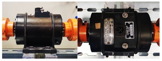
The device used in this work is the MT-103 from SODMEX (Figure 1). The parameters provided by the manufacturer are presented in Table 2. Once the maximum output voltage generated by the torque transducer is 20.9 mV, a load cell is used to amplify the measured signal. This type of sensor assesses the torque values using four strain gauges attached to the meter shaft. The gauges are connected in order to form a Wheatstone bridge circuit. The deformation of the strain gauges causes a resistance alteration, which leads to different voltage levels in the bridge output. These voltage levels have a direct relation to the torque applied to the shaft [11].

Figure 1.
Torque transducer.

Table 2.
Transducer parameters.
4. Rotary Encoder
The rotary encoder used in the WTE was the H38S400B model (Figure 2). This equipment generates 1600 pulses per minute for quadrature outputs, which allows the direction of the TIM rotation to be determined. Additionally, the angular speed can be obtained by processing the pulse signal [12].

Figure 2.
Rotary encoder.
5. Materials and Methods
In this section, the steps taken to accomplish the WTE are presented. Figure 3 shows a diagram of the experimental bench and signal acquisition.

Figure 3.
Setup diagram.
5.1. Test Bench Setup
Initially, the 4 hp TIM was coupled to a DC machine and both of them were firmly bolted to the test bench (Figure 4). The induction motor was driven by the VFD CFW-08 from WEG, which was controlled by a DAQ board NI 6211. The VDF setpoint was generated by an aerodynamic model using two inputs, namely torque and angular speed. The DC machine current was adjusted using a variable resistive load in order to acquire different power levels from the TIM, allowing to draw a power vs. angular speed curve.
5.2. Sensors and Acquisition Board
The encoder and torque meter signals were acquired by the same DAQ used to control the VFD. The NI 6211 board has 16 analogue inputs and 16 digital I/O with 16 bits of resolution [13]. The sample rate is 250 kS/s, which satisfies the Nyquist theorem for this work. The rotary encoder was attached to the back of the motor shaft. In addition, the torque meter was coupled between the two machines as shown in Figure 4.

Figure 4.
Three-phase induction motor (TIM) coupled to a DC machine.
6. Results
With the aim to analyse the effectiveness of the proposed wind turbine emulator, a scenario of wind speed variation was performed. The experimental validation of the WTE was performed by comparing the experimental results obtained by the test bench with the theoretical aerodynamic behaviour of a real wind turbine.
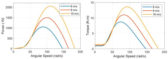
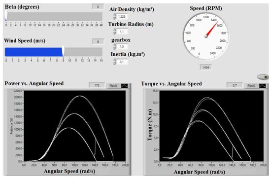
The results were analysed by the characteristics curves of power vs. angular speed and torque vs. angular speed. Therefore, a 1.8 kW wind turbine with a 1.5 gearbox, 1.1 m radius, and 1.225 kg/m3 air density was chosen. For experimental validation, three different wind speeds were applied: 8 m/s, 9 m/s and 10 m/s. In addition, the pitch angle was fixed at 0°.
The theoretical characteristics of power vs. angular speed and torque vs. angular speed of a real wind turbine is shown in Figure 5. This same test was performed for the proposed WTE and its behaviour is shown in Figure 6.

Figure 5.
Wind turbine emulator (WTE) theoretical curves.

Figure 6.
WTE interface and results.
7. Conclusions
The proposed system was able to follow the dynamics of a wind turbine with variations in the resistive load. In this case, it was possible to obtain the characteristics curves for different wind speeds, which were compared with the theoretical values of a real wind turbine. Therefore, the experimental results demonstrated the effectiveness of using the TIM-VFD assembly, since the WTE presented the same behaviour in power vs. angular speed and torque vs. angular speed found in the theoretical wind turbine.
Author Contributions
All authors contributed in writing, proofreading, and providing suggestions for the improvement of the paper.
Conflicts of Interest
The authors declare no conflict of interest.
References
- Moussa, I.; Bouallegue, A.; Khedher, A. New wind turbine emulator based on DC machine: Hardware implementation using FPGA board for an open-loop operation. IET Circuits Devices Syst. 2019, 13, 896–902. [Google Scholar] [CrossRef]
- Gan, L.K.; Shek, J.K.H.; Mueller, M.A. Modeling and Characterization of Downwind Tower Shadow Effects Using a Wind Turbine Emulator. IEEE Trans. Ind. Electron. 2017, 64, 7087–7097. [Google Scholar] [CrossRef]
- Averous, N.R.; Stieneker, M.; Kock, S.; Andrei, C.; Helmedag, A.; De Doncker, R.W.; Hameyer, K.; Jacobs, G.; Monti, A. Development of a 4 MW Full-Size Wind-Turbine Test Bench. IEEE J. Emerg. Sel. Top. Power Electron. 2017, 5, 600–609. [Google Scholar] [CrossRef]
- Guerrero, J.M.; Lumbreras, C.; Reigosa, D.D.; Garcia, P.; Briz, F. Control and Emulation of Small Wind Turbines Using Torque Estimators. IEEE Trans. Ind. Appl. 2017, 53, 4863–4876. [Google Scholar] [CrossRef]
- Sirouni, Y.; Hani, S.E.; Naseri, N.; Aghmadi, A.; Harouri, K.E. Design and Control of a Small Scale Wind Turbine Emulator with a DC Motor. In Proceedings of the 2018 6th International Renewable and Sustainable Energy Conference (IRSEC), Rabat, Morocco, 5–8 December 2018; pp. 1–6. [Google Scholar]
- Nambiar, A.S.; Raja, G.M.; Harindran, K.; Rajan, P.; Sankar, S.S.; Sankar, V.C.J. Design and development of a maximum power point tracker and its testing setup for wind energy conversion system with laboratory level devices. In Proceedings of the 2017 International Conference on Technological Advancements in Power and Energy (TAP Energy), Kollam, India, 21–23 December 2017; pp. 1–5. [Google Scholar]
- Benaaouinate, L.; Khafallah, M.; Mesbahi, A.; Martinez, A. Development of a useful wind turbine emulator based on permanent magnet DC motor. In Proceedings of the 2017 14th International Multi-Conference on Systems, Signals Devices (SSD), Marrakech, Morocco, 20–31 March 2017; pp. 44–48. [Google Scholar]
- Karabacak, M. A new perturb and observe based higher order sliding mode MPPT control of wind turbines eliminating the rotor inertial effect. Renew. Energy 2019, 133, 807–827. [Google Scholar] [CrossRef]
- Sewwandi, K.M.G.Y.; Senarathna, T.S.S.; Lakshika, K.A.H.; Wong, V.Y.; Hemapala, K.T.M.U.; Lucas, J.R.; Porawagamage, G.D. Wind turbine emulator for a microgrid. In Proceedings of the 2017 Innovations in Power and Advanced Computing Technologies (i-PACT), Vellore, India, 21–22 April 2017; pp. 1–6. [Google Scholar]
- Llano, D.X.; McMahon, R.A. Modelling, control and sensorless speed estimation of micro-wind turbines for deployment in Antarctica. IET Renew. Power Gener. 2018, 12, 342–350. [Google Scholar] [CrossRef]
- Hoffmann, K. Applying the Wheatstone Bridge Circuit; HBM Germany: Darmstadt, Germany, 1974. [Google Scholar]
- Hagiwara, N.; Suzuki, Y.; Murase, H. A method of improving the resolution and accuracy of rotary encoders using a code compensation technique. IEEE Trans. Instrum. Meas. 1992, 41, 98–101. [Google Scholar] [CrossRef]
- USB-6211 Specifications—National Instruments. Available online: http://www.ni.com/pdf/manuals/375195d.pdf (accessed on 22 October 2019).
Publisher’s Note: MDPI stays neutral with regard to jurisdictional claims in published maps and institutional affiliations. |
© 2019 by the authors. Licensee MDPI, Basel, Switzerland. This article is an open access article distributed under the terms and conditions of the Creative Commons Attribution (CC BY) license (https://creativecommons.org/licenses/by/4.0/).