Proceeding Paper

Mechanical Line Fit Model to Monitor the Position of KM3NeT Optical Modules from the Acoustic and Compass/Accelerometer Sensor System Data †

by
Dídac D. Tortosa
on behalf of the KM3NeT Collaboration
Universitat Politècnica de València (UPV) – Institut d’Investigació per a la Gestió Integrada de les Zones Costaneres (IGIC), Paranimf 1, 46730 Grau de Gandia (València), Spain
Presented at the 6th International Electronic Conference on Sensors and Applications, 15–30 November 2019; Available online: https://ecsa-6.sciforum.net/.
Proceedings 2020, 42(1), 33; https://doi.org/10.3390/ecsa-6-06583
Published: 14 November 2019

Abstract

:
The KM3NeT deep-sea neutrino telescope will use thousands of Digital Optical Modules (DOMs) forming a 3D array to detect the Cherenkov’s light produced by the particles generated after a neutrino interaction in the medium. The DOMs are arranged in Detection Units (DUs), structures anchored and maintained vertical by buoyancy each one containing 18 DOMs at different height. The DOMs are, thus, subject to movements due to sea currents. For a correct reconstruction of events detected by the telescope, it is necessary to monitor the position of each DOM with 10 cm accuracy. For this, an Acoustic Positioning System (APS) with a piezo-ceramic transducer installed in each DOM and a long baseline of acoustic transmitters and receivers on the seabed is used. Besides, there is a system of compass/accelerometers in the DOMs to determine their orientation. Then, a mechanical model is used to reconstruct the shape of the DU taking as input the information from the positioning sensors and using the sea current velocity as free parameter of the DU Line Fit method. The mechanical equations consider the buoyancy and the drag force of any item in the DU line. This work describes the data process of the different sensors and systems to obtain the fit shape of DUs, the situation for the first DUs installed as an example and to study the viability and define the full process to apply in KM3NeT.

1. Introduction

KM3NeT is an underwater detector of neutrinos, presently under development with the aim to perform neutrino astronomy and to determine the neutrino mass hierarchy [1]. Its philosophy is based on his predecessor ANTARES [2,3], arranging a 3D array of Digital Optical Modules (DOMs) in the Mediterranean Sea to detect the Cherenkov light produced by neutrino interactions in the water. These DOMs are arranged in different Detection Units (DUs), flexible vertical structures anchored on the sea bed with 18 DOMs each one. KM3NeT is composed of two detectors with its different science objectives: ARCA is the KM3NeT node located 100 km offshore Portopalo di Capo Passero at 3500 m depth. Its aim is to study high energy neutrions of cosmic origin. It will be composed by two blocks of 115 DUs each distributed in ∼1 km3. ORCA will have 115 DUs but in a more compact structure than ARCA (∼0.018 km 3 ). It is located 40 km offshore Toulon at 2500 m of depth to study neutrino oscillations and neutrino mass hierarchy. Presently one ARCA DU and four ORCA DUs are installed and operational.
The precise determination and orientation of each DOM together with a nanosecond time synchronization are crucial to reconstruct the incoming direction of the detected neutrino. Since GPS signals are not available on the ocean depths, it is necessary to use an Acoustic Positioning System (APS). The APS uses emitters anchored in geo-referenced positions of the sea floor. Each DOM of the detector has a piezo-ceramic installed inside glued to the interior of the glass sphere. Therefore, the APS can monitor the location of the DOMs with an acoustic triangulation method.
It is also important to determine the orientation of the DOMs to locate which PMT is directly looking the path of the neutrino detected. To obtain the orientation, each DOM has an accelerometer and a compass. This set up an Attitude and Heading Reference System (AHRS) in KM3NeT. These sensors are calibrated before the DU installation.
The combined systems provide spatial location and orientation of each DOM. The problem appears when some of these sensors present failures and some data is missing. To deal with this, the idea of this work is to reconstruct the shape of the DU using a mechanical model that uses an effective value of the sea current velocity and the inputs of the APS, AHRS data and mechanical properties of the DU components.

2. Methods

The monitoring of the position and orientation of the DOMs is based on the APS data and the orientation angles from the AHRS that provide the Yaw, Pitch and Roll values for each DOM. The two systems are totally independent and running on-line. Mean values of position and orientation of each DOM are provided every 10 min. In this time interval, the DOM position and orientation vary respectively less than 20 cm and 3 deg., under typical currents (10 cm/s).
In this section the APS, AHRS and Mechanical Model are presented in detail.

2.1. Acoustic Positioning System (APS)

The Acoustic Positioning System (APS) is a combination of a RAPS (Relative APS) and a NAAPS (Navigation and Absolute APS). Assuming the knowledge of the absolute position of each fixed/anchored item of the telescope, it can provide the relative location of the moving elements. The APS of KM3NeT consists of a synchronized Long Baseline System with acoustic emitters in fixed positions at the sea bed and a piezo-ceramic receiver located at the bottom of each DOM. A fixed hydrophone on each DU base is used as reference. According to the first studies, the APS data accuracy is better than 20 cm [4,5]. At present, only three Autonomous Beacons (ABs) are deployed in the detector field. These ABs can emit different acoustic signals. For the APS, they emit sweep signals during 1 min every 10 min, asynchronously. All signals are detected through cross-correlation method, and the APS register the Time of Arrival (ToA) for every signal. To know the Time of Emission (ToE), the APS uses the fixed hydrophone on the DU base as reference time. In case the hydrophone is not available, the receiver of the lowermost floor, DOM1, is used as reference. From this, it is possible to measure the Time of Flight (ToF) and, using the knowledge of sound velocity in water, derive the distance between emitter and receiver. From the distances to the three ABs, the position is determined by triangulation. Assuming that the distance between emitter and reference receiver is known ( d i s t r e f ), the ToE to every AB can be estimated T o E A B = T o A T o F = T o A d i s t r e f c s o u n d , so it is possible to calculate the ToF for every AB to any receiver. Once the ToF and location of the ABs are known, the triangulation method can be applied to create a system of equations and resolved it by minimum quadratic solution. At the end, the APS data provides the location of every acoustic receiver in the detector.

2.2. Attitude and Heading Reference System (AHRS)

The orientation of DOMs is provided by a compass and tilt-meter installed in an electronic board into the DOMs. They are forming the Attitude and Heading Reference System (AHRS) of KM3NeT. The orientation of each DOM is expressed through its rotation in rotation angles ( Y a w , P i t c h and R o l l ). The boards used are developed within the KM3NeT collaboration and are calibrated before their installation. The accuracy of the system is estimated to be smaller than 3.5 degrees [6].

2.3. Mechanical Model (MM)

The aim of the MM is to determine the position of each DOM based on the mechanical properties of the DU, the information provided by the APS and AHRS. Using as fitting parameters the effective sea current direction and velocity, it is capable to reconstruct the shape of the line and interpolate the DOM positions for DOMs with piezo sensors that have failures. The MM is similar to the MM used for ANTARES, and it is based in the computation of drag and buoyancy forces [7].
The zenith angle ( α ) at a given point of the line is given by the ratio of horizontal (drag force Equation (2)) and vertical (buoyancy Equation (3)) forces summed over all line elements above this height z (Equation (1)):
t a n α = F ( z ) W ( z ) = g ( z )
where α is the zenith angle at height z that depends on the horizontal force ( F ( z ) ) and vertical force ( W ( z ) ).
F ( z ) = f ( z ) v 2 = i = 1 18 f D O M + f c a b l e i + f c a b l e l a r g e h z z + f t o p b u o y v 2
where F ( z ) represents the drag force at height z of the line (being h the maximum height of the DU). It depends on the drag parameter f of all elements and on the sea current velocity v.
W ( z ) = i = 1 18 W D O M + W c a b l e i + W c a b l e l a r g e h z z + W t o p b u o y
where W ( z ) represents the vertical force that is depending of the buoyancy force W of all elements along it.
By integration of equation g ( z ) over z, the total displacement between the items in height z can be obtained (Equation (4)):
r ( z ) = 0 z g ( z ) d z = n q z m q n p q 2 l n 1 q p z v 2
where r ( z ) represents the vertical displacement in the height z of the line, and the rest of parameters are
m = i = 1 18 f D O M + f c a b l e i + f c a b l e l a r g e + f t o p b u o y
n = i = 1 18 1 h f D O M + f c a b l e i + 1 h f c a b l e l a r g e + 1 h f t o p b u o y
p = i = 1 18 W D O M + W c a b l e i + W c a b l e l a r g e + W t o p b u o y
q = i = 1 18 1 h W D O M + W c a b l e i + 1 h W c a b l e l a r g e + 1 h W t o p b u o y
The MM considers that r ( z ) is, according to Equation (4), the mechanical constants ( M M c o n s t . ( z ) ) times v 2 . Therefore, if the r ( z ) value is taken by APS data, and the M M c o n s t . ( z ) are known too (Figure 1), it is possible to obtain an effective sea current velocity. Studying this displacement from vertical position versus these mechanical constants, it is possible to calculate the slope of a linear fit. This slope value is the square of the effective sea current velocity. Then, knowing v, it is possible to reconstruct the shape of the DU studying the points on the DOMs height.
The sea current velocity is assumed to be the same along the entire line and the detector.

Mechanical Properties of KM3NeT to Calculate the Mechanical Constants

All DUs in KM3NeT have the same configuration. A DU base is anchored on the sea bed using a dead weight. Then DOMs are set at different heights by using two parallel ropes where the DOMs are fixed. The distance to the first DOM is larger, and the rest of DOMs are approximately equidistant. To increase buoyancy, the DU has a top buoy. Therefore, four different items (long string, inter DOMs strings, buoy string and top buoy) are considered along the line.
All DOMs in KM3NeT are identical, a glass sphere with 43 cm of diameter. The rest of the elements in a DU are different depending whether the detector is ORCA or ARCA. ARCA has a 690 m DU height, a 64 m long first cable and top buoy buoying 1030.05 N, whereas ORCA has a 197 m DU height, a 27 m long first cable and top buoy buoying 1226.25 N. Taking these parameters, it is possible to calculate the buoyancy and the drag parameter (Equation (5)) for each element (Table 1):
f j = 1 2 C w , j A j ρ
where f j represents the drag parameter on the element j that depends of its drag coefficient C w , its cross section A and the density of the environment ( ρ ).
About the drag force calculation for the cable between DOMs, the cable in ARCA is around 37 m long and ORCA around 9 m long but with some variations depending of the floor. The cable between DOMs is the same type of cable as in the first part of the line, so its buoyancy is also null.
In the next section, the reconstruction of the line is described in detail from APS and AHRS data to obtain the DU shape.

3. Mechanical Line Fit Model

The reconstruction of the shape of the line will be done using the Equation (4) with the effective sea current velocity as fit parameter, using as input data the position of DOM piezos from the acoustic system and the angular orientation of DOMs from the AHRS.
The effective sea current direction ( ω ) can also be obtained by analyzing the direction of the transverse displacement of DOMs. Once determined these parameter values, the reconstruction of the line is possible reusing Equation (4) for every DOM according to the height, z, and computing the transverse displacement relative to its DU base position. The reconstruction of the positions with the Mechanical Line Fit model is considered an improvement with respect to the direct location from APS [8], especially for the case of DOMs with missing or noisy acoustic data. To obtain a good fit and value of effective sea current velocity, it is quite important not to include the data from noisy DOMs, so a pre-filter is needed.
With respect to the orientation of the DOMs, the idea is to study the trend along the line (for every DOM) and, if some DOM is missing or wrong, estimate the value by doing an interpolation according to the rest of DOMs. Thus, the AHRS reconstruction needs the previous data filter as well.

4. Results and Conclusions

The viability of this preliminary procedure for the APS data analysis is shown in this section. For this case, one week (13/09/2019 to 20/09/2019) of data from the 3rd DU of ORCA (DU3) is studied (see Figure 2).
The APS and AHRS in KM3NeT provide the location and the orientation for all DOMs. The APS data analysis using the Mechanical Line Fit model is able to obtain the positions of DOMs even in the case of missing data. Moreover, a filtering process can be applied to discard anomalous data values from APS, AHRS or fitting parameters of the model (efficient sea current direction and velocity).
In this work, the analyses of the APS data procedure have been applied to the reconstruction of the locations of piezo-ceramics. The final implementation of the Mechanical Line Fit model is still in progress and will be applied to obtain the location of the centre position and the orientation for every DOM. Once all this is being defined, an automatic procedure for the monitoring of the position and orientation of all DOMs in KN3NeT will be implemented.

Funding

We acknowledge the support from Ministerio de Ciencia, Innovación, Investigación y Universidades (MCIU): Programa Estatal de Generación de Conocimiento (refs. PGC2018-096663-B-C43) (MCIU/FEDER), and MultiDark Consolider.

Conflicts of Interest

The authors declare no conflict of interest.

References

  1. Adrian-Martinez, S.; Ageron, M.; Aharonian, F.; Aiello, S.; Albert, A.; Ameli, F.; Anassontzis, E.; Andre, M.; Androulakis, G.; Anghinolfi, M.; et al. Letter of intent for KM3NeT 2.0. J. Phys. G Nucl. Part Phys. 2016, 43, 084001. [Google Scholar] [CrossRef]
  2. Ageron, M.; Aguilar, J.A.; Al Samarai, I.; Albert, A.; Ameli, F.; André, M.; Anghinolfi, M.; Anton, G.; Anvar, S.; Ardid, M.; et al. ANTARES: The first undersea neutrino telescope. Nucl. Instrum. Methods A Accel. Spectrom. Detect. Assoc. Equip. 2011, 656, 11–38. [Google Scholar] [CrossRef]
  3. Ardid, M. ANTARES: An underwater network of sensors for neutrino astronomy and Deep-Sea Research. Ad Hoc Sens. Wirel. Netw. 2009, 8, 21–34. [Google Scholar]
  4. Viola, S.; Ardid, M.; Bertin, V.; Lahmann, R.; Pellegrino, C.; Riccobene, G.; Saldaña, M.; Sapienza, P.; Simeone, F. Acoustic Positioning System for KM3NeT. In Proceedings of the 34th International Cosmic Ray Conference, The Hague, The Netherlands, 30 July–6 August 2015. [Google Scholar] [CrossRef]
  5. Viola, S. KM3NeT Acoustic Positioning and Detection System. EPJ Web Conf. 2019, 216, 02006. [Google Scholar] [CrossRef]
  6. Riccobene, G. The Positioning System for KM3NeT. EPJ Web Conf. 2019, 207, 07005. [Google Scholar] [CrossRef]
  7. Adrián-Martínez, S.; Ageron, M.; Aguilar, J.A.; Al Samarai, I.; Albert, A.; André, M.; Anghinolfi, M.; Anton, G.; Anvar, S.; Ardid, M.; et al. The Positioning System of the ANTARES Neutrino Telescope. JINST 2012, 7, T08002. [Google Scholar] [CrossRef]
  8. Ardid, M.; Bou-Cabo, M.; Diego-Tortosa, D.; Martínez-Mora, J.A.; Poirè, C. Underwater Acoustic Positioning System for the Monitoring of KM3NeT Optical Modules. In Proceedings of the INTER·NOISE19, Madrid, Spain, 16–19 June 2019. [Google Scholar]
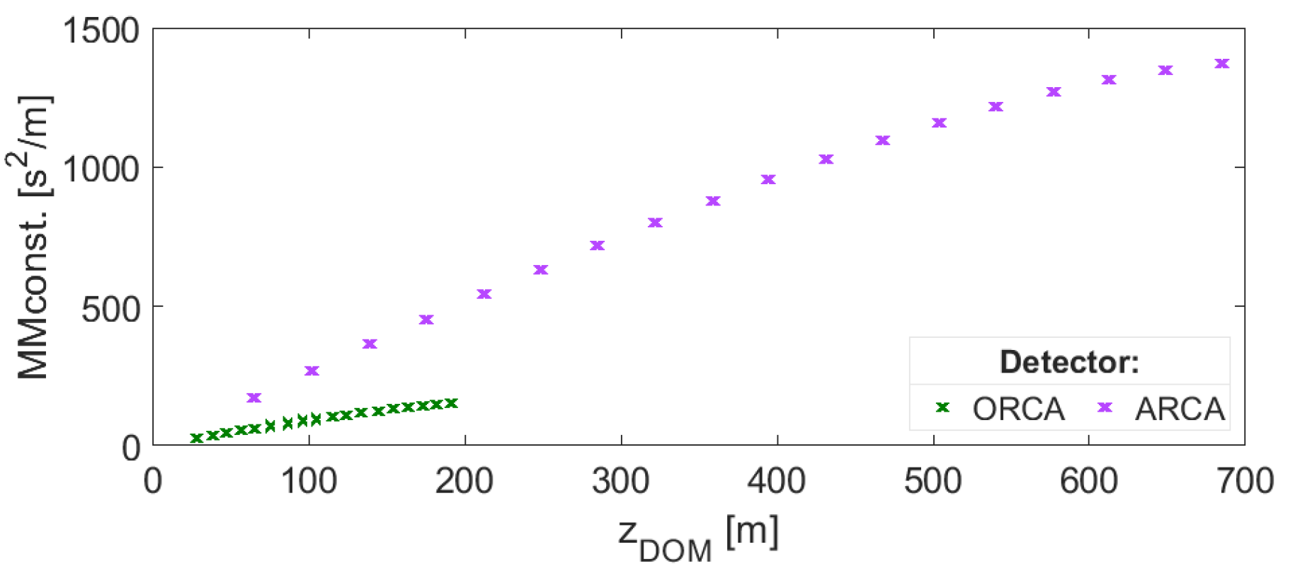
Figure 1. ORCA and ARCA M M c o n s t . ( z ) calculation in every floor (DOM) of a DU.
Proceedings 42 00033 g001
Figure 2. KM3NeT preliminary. (a) APS filter applied to the data. (b) Effective sea current direction calculated from APS data estimated for each DOM. (c) Effective sea current direction evaluated from APS data estimated for all over the DU. (d) Example of Mechanical Line Fit Model reconstruction in a measure.
Proceedings 42 00033 g002
Table 1. Mechanical properties of the elements in a line of KM3NeT.
DetectorProperty Elements
DOM long string top buoy
ARCA f [ N s 2 / m 2 ] 52.86659.10482.66
W [ N ] 125.5701030.05
ORCA f [ N s 2 / m 2 ] 52.86283.92482.66
W [ N ] 125.5701226.25
Publisher’s Note: MDPI stays neutral with regard to jurisdictional claims in published maps and institutional affiliations.