1. Introduction
A major portion of existing infrastructure worldwide continues to be at potential risk of failure on account of aging, corrosion and overloading, principally during earthquakes. Moreover, most of the construction carried out is not in conformance with design codes. Their prolonged use beyond design service life proliferates damage that manifests itself usually in the form of cracks. In recent years, buildings have collapsed causing catastrophic impact on life and safety. India experienced the worst building fall-down disaster in 2013 in Thane owing to illegitimate construction. The Bangladesh Savar building collapse of 2013 has remained the deadliest fortuitous structural failure in modern human history as the detected cracks were left unattended and unrepaired. Prevailing damage multiplied due to vibrations from generators. Three buildings collapsed in the historic centre of Rio de Janeiro, Brazil on January 2012 since the construction work violated local building codes. South Korea suffered the largest peacetime disaster in 1995 when the Sampoong department store disintegrated as vibration of the air conditioning widened cracks to about 10 cm causing complete failure of floor slabs. Such tragic disasters in civil structures cause a large number of fatalities as well as social and monetary setbacks. In common terms, damage refers to the change in the physical characteristic attributing to detrimental change in structural performance. Any damage at local level should be vigilantly examined and repaired in order to terminate its further propagation and prevent progressive collapse. Hence, monitoring the condition of these structures to carry out basic maintenance has become crucial to our civilization. Evaluation of the health of building stocks is significant after natural hazards such as earthquakes, or man-made disasters such as terrorist attacks.
Traditionally, the safety evaluation of buildings in India is carried out through periodic visual inspection and some kind of non-destructive testing (NDT), whenever the need is felt. The downside of conventional techniques, such as visual inspection and non-destructive testing (NDT), is that these require time and effort, require that the vicinity of damage is known a priori and that the portion of structure being inspected is readily accessible. The recurrent check-ups, as well as the improbable failures, which cannot be entirely eliminated, increase maintenance costs, operating expenses and vehicle down-time. This necessitates in-service checks for strength and durability of structures allowing early detection and diagnosis of damage.
This calls for an urgent need to facilitate real time structural assessment for early detection and diagnosis of cracks. Structural health monitoring (SHM) identifies damage by virtue of changes in the overall vibration response of the buildings. The change in modal parameters (natural frequency, mode shapes and modal damping coefficient) gives an indication of the possible damage. Thus, SHM is the process of acquiring and analysing data from on-board sensors to determine the health of a structure [
1,
2,
3]. The examination of a system encompasses sporadically sampled dynamic response from a range of sensors, extrication of damage-sensitive parameters from obtained response and their statistical analysis to determine the instant state of a system’s health. SHM encapsulates the technology and algorithms for sensing the condition of a structure, diagnosing the current state, conducting a prognosis of probable future performance and imparting information for its maintenance, safety and emergency actions. This enhances the serviceability and integrity of structures resulting in their reduced life cycle cost. The promising domain of SHM monitors the condition of structures in view of natural hazards like earthquakes and man-made disasters like terrorist attacks, vibrations from generators, air-conditioners, enabling well managed repair, rehabilitation and refurbishment facilities to minimise the impact of the disaster. Research findings can find applicability in predicting distress in a building so that appropriate retrofitting and strengthening can be performed to prevent building failure.
The experiment was performed on a one-third scaled prototype model of a six story RC frame with masonry infill in the building dynamics laboratory of CBRI. Progressive damage was introduced by virtue of cracks in infill. Numerous different sets of forced, free and ambient vibration tests were performed to determine natural frequencies for each of these five damage cases using frequency-domain operations such as fast fourier transform (FFT).
The paper focuses on real-time damage detection based on vibration studies accomplished by the CBRI structural health monitoring team. The experiment was performed on the 1:3 scaled model of a six-story RC frame with masonry infill in the building dynamics laboratory of CBRI. The forward problem is attended by inducing step-by-step damage in infill to investigate the changes in dynamic response as a result of change in the physical properties of the structure. Recorded time histories are processed for frequency response spectra (FRS) with fast Fourier transform (FFT) and mode shapes are obtained. Changes in natural frequency and modal curvature for each of the five damage cases are analysed for damage detection and location in the structure. An algorithm for damage identification viz. the curvature damage factor (CDF) approach is presented.
2. CSIR-CBRI Studied Model
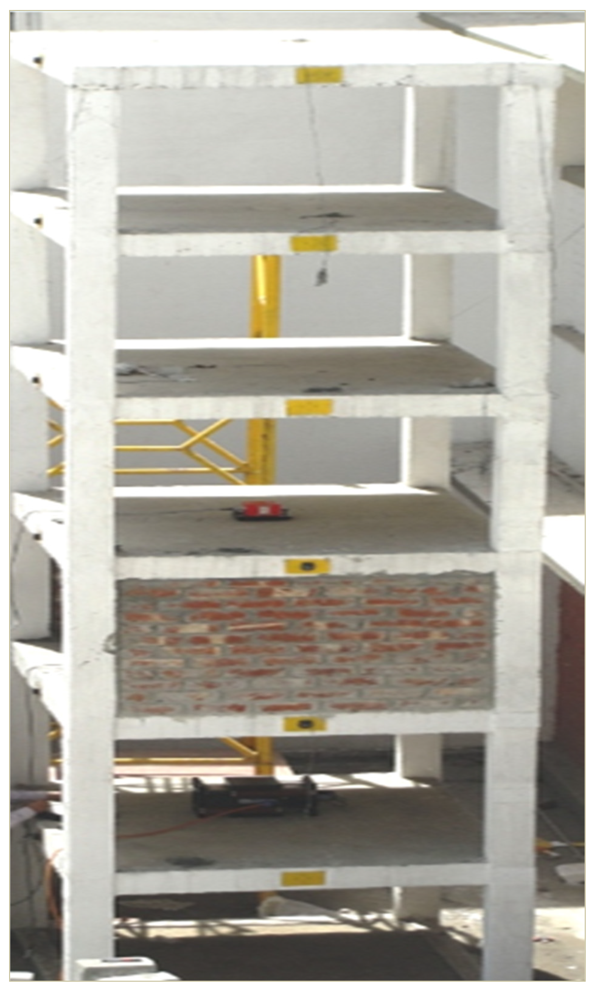
The prototype frame used for this study is a 1:3 scaled down six-storey, one by one bay, RC frame structure designed and constructed at the Building Dynamics Laboratory of the CSIR-Central Building Research Institute (CSIR-CBRI) (
Figure 1). The extent of this research effort follows the Indian codes and practices in design and construction of RC frame with masonry infill.
The building model used in the research study is 2000 mm by 1500 mm in plan dimension with 1100 mm storey height. The building consisted of four columns (150 × 150 mm size), beams (100 × 175 mm size) and slabs (65 mm thick), constructed in M20 grade concrete and Fe415 reinforcement. The building was designed in accordance with IS 456-2000. The RC columns comprised of four number 12 mm dia. bars width 6 mm lateral ties, spaced at 150 mm c/c. The RC beams comprised of 2 numbers each 12 mm dia. bars at top and bottom reinforcement with 6 mm dia. stirrups at 120 mm c/c, and RC slab having 6 mm dia. at 150 mm c/c reinforcement, in both the directions. The stiffness of the prototype model was varied with the introduction of masonry infill in a storey along the direction of the shorter span of the building (
Figure 1). The thickness of masonry infill was 100 mm spread across a length and height of 1350 mm and 930 mm, respectively.
3. Experimental Investigation
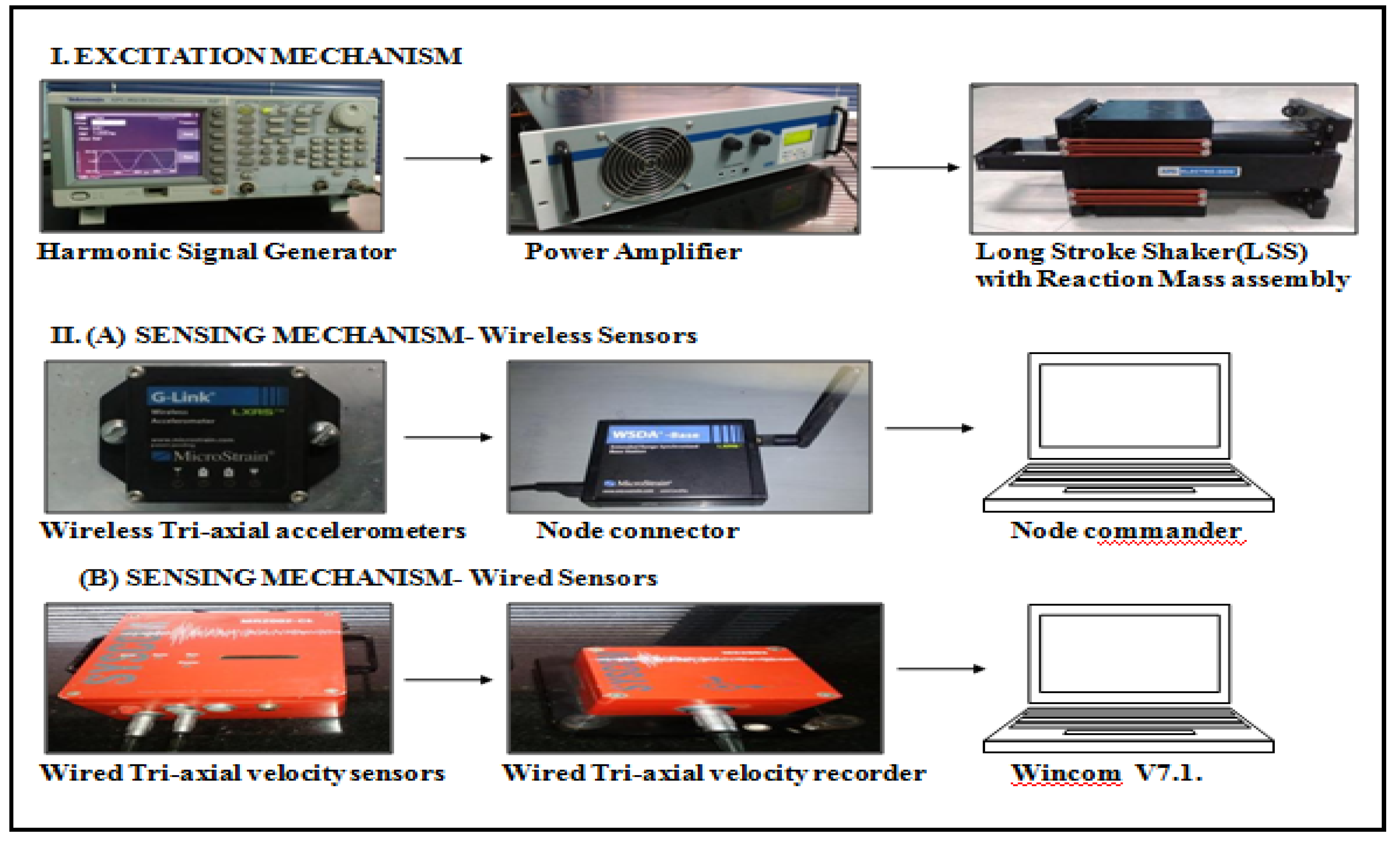
The forced vibration testing comprised of a low amplitude vibration, set up by an APS-400 electrodynamic long stroke shaker (LSS) installed at the first floor. The Tektronix AFG 3021B harmonic signal generator produced waveforms particularly sine continuous, sine sweep, which were low power signals.
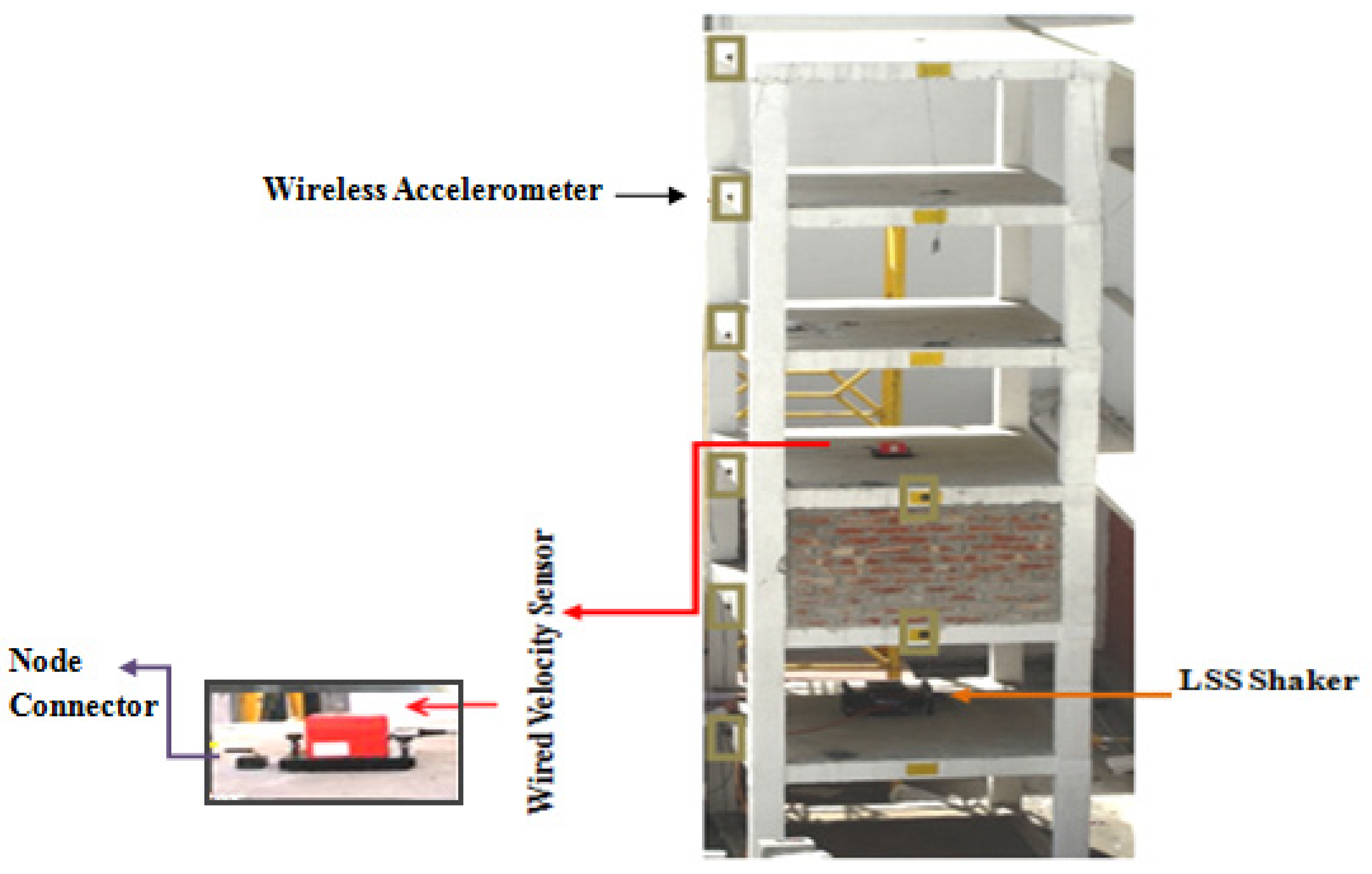
These signals were amplified to 5V using the Power Amplifier before feeding it to the LSS. The LSS was operated under continuous sine excitation at different frequencies and in sine sweep excitation mode. The experimental set-up for the test programme is shown in
Figure 2 and
Figure 3.
The sensing network comprised of eight MICROSTRAIN LXRS Tri-axial wireless accelerometers, six of which were installed on the beam in the direction of longer span (X-axis), while the remaining two were installed along the shorter span (Y-Axis) of the framed structure. These were used to record acceleration at required locations in a structure. SYSCOM MR2002-CE Tri-axial wired velocity sensors were also employed in the present study containing active geophones capable of recording time series data with remarkable accuracy. Wincom V7.1 was used as communication software for base correction and for storage from the recorder to data processing unit. The wireless sensors were fixed using 5 mm thick aluminium plate anchored to RC floors/beam, whereas the wired velocity sensors were placed on the surface, i.e., the floor level of the RC frame building. The sampling rate used was 128 Hz, hence a total of 3840 data sets were recorded in 30 s for post processing.
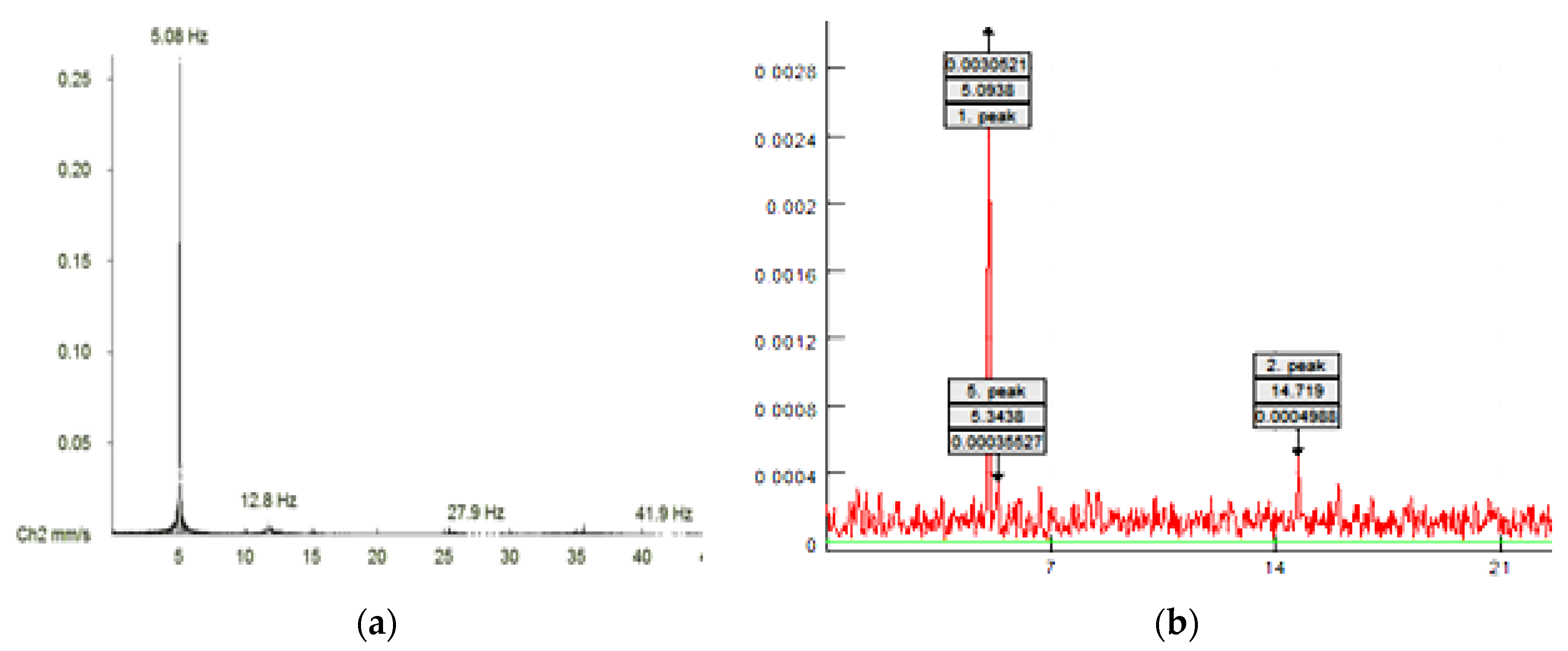
The data acquisition system (DAS) recorded the excitation and the response signals through a discrete-time series. The data processing was done using VIEW 2002 and SIGVIEW software packages for wired and wireless sensors, respectively. The signals were acquired in the form of time history, which was then analysed using FFT to obtain FRS. The peak values obtained in the frequency response function plots correspond to the modal frequencies.
4. Damage Assessment of RC Building
Damage is identified as any change occurring in a system with respect to its pristine state, which may infringe on its present or future performance. Changes in physical attributes such as material, geometry or boundary condition represents a damaged state. The fundamental principal in vibration-based damage detection is that any damage will considerably vary the stiffness, mass or energy dissipation properties of the system, which further modifies the dynamic response of the system viz. modal frequency, damping and mode shape, over time [
5,
6,
7] (
Figure 4). The main aim is to efficiently detect damage at the earliest possible stage.
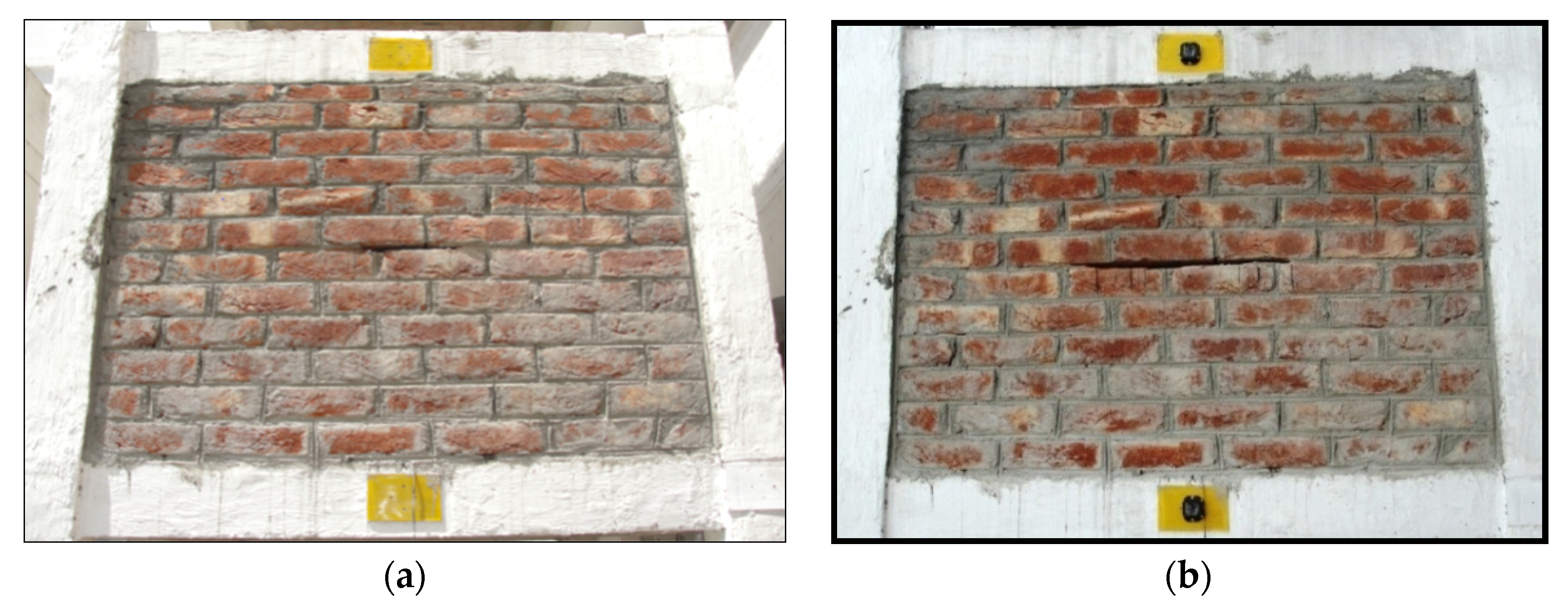
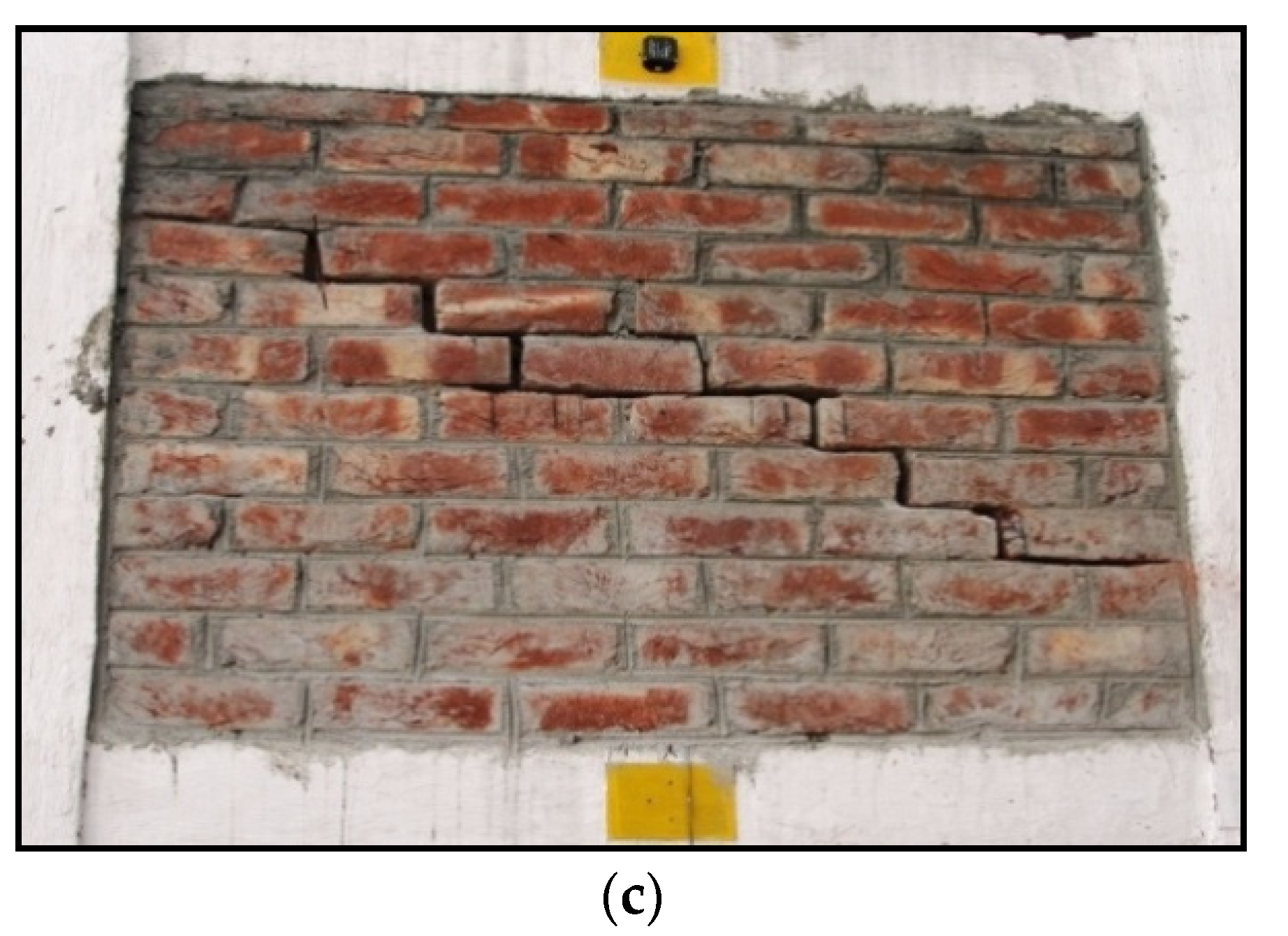
The forward problem is attended in this study. The structural damage is caused by addition of infill in the second story along the direction of the shorter span, as well as by subsequently induced diagonal stepped cracks in the masonry. This brings about an increase and decrease in stiffness, respectively, that alters the shear capacity of the structure. Five levels of crack stimulation along their length (D1, D2, D3, D4 and D5) are studied during testing (
Figure 5). The modal parameters are obtained through the vibration test at a certain level of damage.
The non-model approach, which is a direct response-based technique involving damage indices, has been applied in the research work. The damage indicators such as change in frequencies, modal curvature and modal derivatives are considered [
8,
9]. The analysis of shift in dynamic parameters of buildings for various damage cases is captured using change in modal curvature [
4]. The damage identification algorithm viz. the curvature damage factor (CDF) approach is presented.
4.1. Damage Detection: Change in Frequency
In the following experiment, the inclusion of an infill wall increases stiffness, and increase in frequency responses of a structure can be used to detect the variation in natural frequencies. Although frequency responses are easy to measure with a small number of sensors, they are global reflections of the system dynamic property, and one single frequency response function oftentimes lacks the sensitivity to measure local variation of dynamic characteristics when in-filled. Hence, a large number of measured natural frequency shifts are analysed. The shift in modal parameters such as natural frequency on account of the inclusion of an infill wall has been observed (
Figure 6).
The results showing reduction in frequencies corresponding to each damage level is compared (
Table 1). The frequency based approach is a reflection of the global nature of the system. Hence, this measure of correlation between intact and damaged state serves as an indicator of damage without showing location of damage (
Appendix A).
4.2. Damage Detection: Curvature Mode Shape (CMS) Approach
The underlying concept of this approach is that at a given location, the loss of stiffness will lead to increments in the curvature. This method has been proposed and successfully used for locating the damage in cantilever beam by Pandey et al. [
16,
17,
18,
19,
20,
21]. The curvature of a beam under pure bending moment M may be given as
where,
v denotes the transverse displacement of the beam. From the displacement mode shapes, curvature modes are obtained by using a central difference approximation, as
where,
i is the floor level and
l is the storey height. Thus, the curvature of the
jth mode shape may be obtained by the value of vertical displacement of the same mode shape.
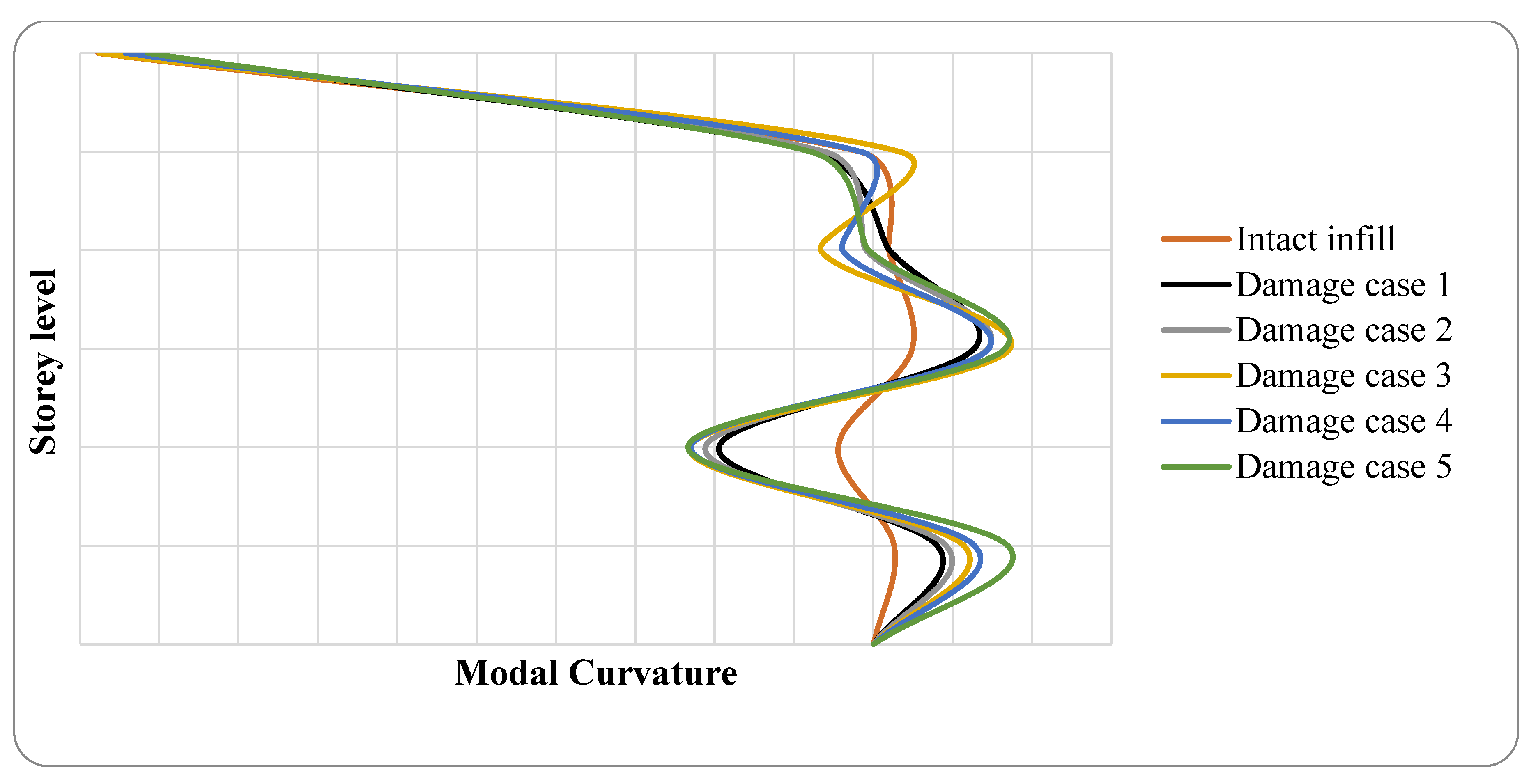
Figure 6 presents the comparison between changes in curvature of mode shapes at different damage extents for fundamental mode. It is observed that there is a clear deviation of modal curvature for damaged situation to undamaged situation. The maximum peaks for the mode, as seen in the graph, corresponds to the same damage location, i.e., the second storey of the masonry infilled RC building.
The results show that the difference of curvature mode shapes from intact and damaged structures can be a good indicator for damage location. For higher modes, the difference in modal curvature shows several peaks, not only at the damage location but also at other positions, which may lead to a false indication of damage. To avoid false alarm, the first mode has proved to provide the most reliable curvature.
4.3. Damage Detection: Curvature Damage Factor (CDF) Approach
Foti (2007, 2013) discussed (i) the Change in Mode Shapes Method and (ii) Mode Shapes Curvature Method for predicting damage location and severity [
10,
11,
12,
13,
14,
15]. In order to eliminate the possibility of false alarm, the
CDF was calculated as:
where,
N is the total no of modes considered,
—curvature mode shape of intact structure and
that of the damaged structure.
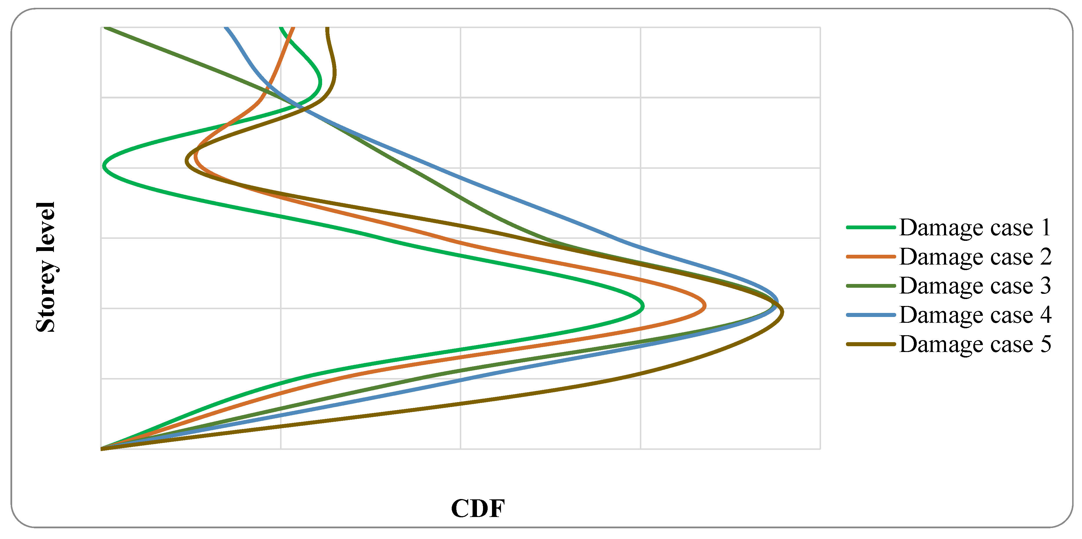
CDF is based on average absolute difference in intact and damaged curvature mode shapes of all modes (
Figure 7).
In this study, the fundamental mode (
N = 1) of five damage cases were considered for the computation of
CDF and these values were plotted against each storey level.
Figure 7 clearly shows that the peaks of
CDF values also increase with increase in damage levels. It indicates change in stiffness of the structure due to progressive damage in masonry infill.
5. Results and Conclusions
The non-model approach, which is a direct response-based technique involving damage indices, has been applied in the research work. The damage indicators such as change in frequencies, modal curvature and modal derivatives are considered.
Frequency based damage indices (DI) are a reflection of the global nature of the system. The probability of errors is relatively low with respect to other methods. However, it proves to be less sensitive in detecting intensity of damage and a large number of frequency shifts are to be analysed for more reliable data.
The study concludes that the variations in curvature mode shapes are more sensitive than those in displacement mode shape since the curvature mode shapes are localised to the damage location. Significant deviation in peaks corresponding to the increase in damage size or intensity is thus evident.
Results show that curvature of mode shape is a good damage sensitive parameter to detect and locate damage in structures. This is also due to the fact that second modal derivative is relatively more sensitive to minute perturbations in the structural system.
The CMS approach also shows peaks owing to high noise levels, which may lead to a false indication of damage. To eliminate this problem, CDF shows the absolute change in mode shape values between two states.
Author Contributions
Conceptualization and Methodology, A.C. and H.B.; Software, H.B.; Formal Analysis, H.B.; Investigation, A.C. and H.B.; Resources, H.B. and S.P.; Data Curation, H.B.; Writing—Original Draft Preparation, H.B.; Writing—Review and Editing, A.C.; Visualization, S.P.; Supervision, A.C. and S.P.; Project Administration, A.C.; Funding Acquisition, A.C.
Conflicts of Interest
The authors declare no conflicts of interest. The funders had no role in the design of the study; in the collection, analyses, or interpretation of data; in the writing of the manuscript, or in the decision to publish the results.
Appendix A
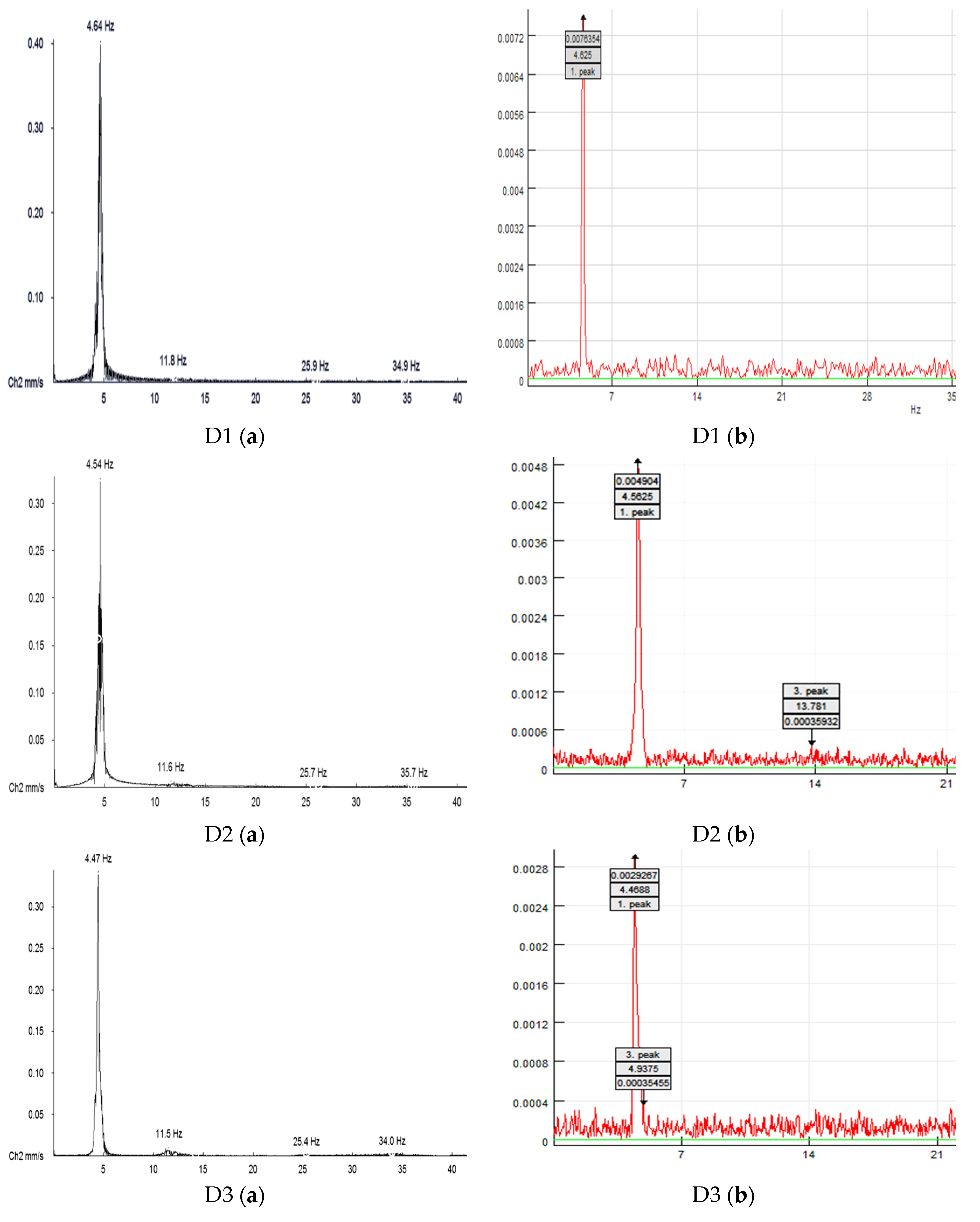
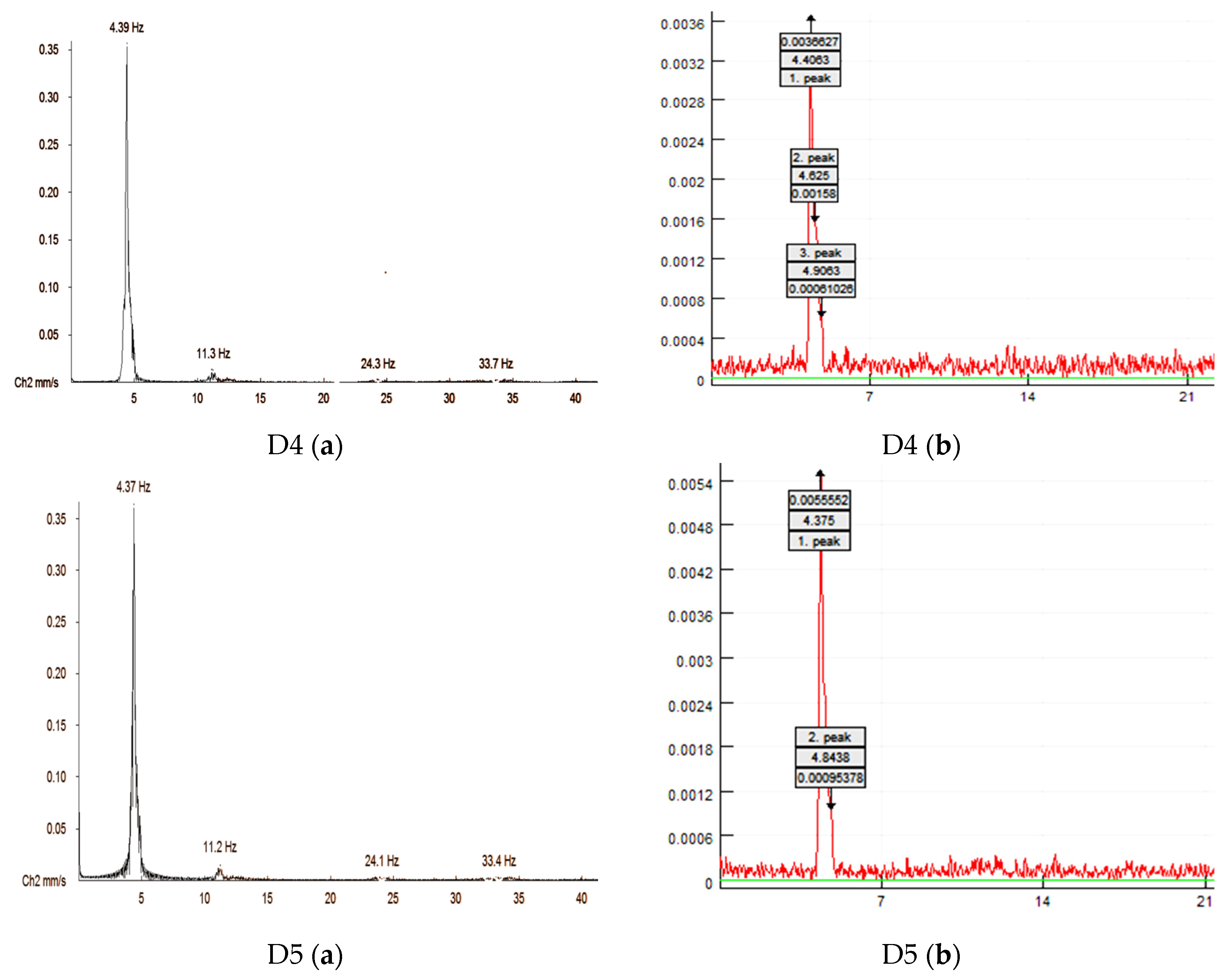
Appendix A shows the reduction in frequencies corresponding to each damage level as obtained by frequency response spectra (FRS) via wireless sensors and wired velocity sensors (
Figure A1).
Figure A1.
FRS showing frequency of RC frame with infill in shorter direction (1.5 m) in five damage cases obtained via (a) wired velocity sensors and (b) wireless accelerometers.
Figure A1.
FRS showing frequency of RC frame with infill in shorter direction (1.5 m) in five damage cases obtained via (a) wired velocity sensors and (b) wireless accelerometers.
References
- Carden, E.P.; Fanning, P. Vibration based Condition Monitoring: A Review. Struct. Health Monit. 2004, 3, 355–377. [Google Scholar] [CrossRef]
- Chang, P.C.; Flatau, A.; Liu, S.C. Review Paper: Health Monitoring of Civil Infrastructure. Struct. Health Monit. 2003, 2, 257–267. [Google Scholar] [CrossRef]
- Chopra, A.K. Dynamics of Structures, Theory and Applications to Earthquake Engineering, 2nd ed.; Prentice Hall: Upper Saddle River, NJ, USA, 2001. [Google Scholar]
- Chaurasia, A.; Panigrahi, S.K.; Patel, S.S. Damage Identification of Reinforced Concrete Beam Using Modal Curvature Approach. Smart Struct. Syst. 2018, 77, 337–341. [Google Scholar]
- Chung, H.-C.; Enomoto, T.; Shinozuka, M.; Chou, P.; Park, C.; Yokoi, I.; Morishita, S. Real Time Visualization of Structural Response with Wireless MEMS Sensors. In Proceedings of the 13th World Conference on Earthquake Engineering, Vancouver, BC, Canada, 1–6 August 2004. [Google Scholar]
- Clough, R.W.; Penzien, J. Dynamics of Structures, 2nd ed.; McGrawHill International Editions: New York, NY, USA, 1993. [Google Scholar]
- Cooley, J.W.; Tukey, J.W. An Algorithm for the Machine Calculation of Complex Fourier Series. Math. Comput. 1965, 19, 297–311. [Google Scholar] [CrossRef]
- Doebling, S.W.; Farrar, C.R.; Prime, M.B.; Shevitz, D.W. Damage Identification and Health Monitoring of Structural and Mechanical Systems from Changes in their Vibration Characteristics: A Literature Review; Los Alamos National Laboratory Report LA-13070-MS; USDOE: Washington, DC, USA, 1996. [Google Scholar]
- Doebling, S.W.; Farrar, C.R.; Prime, M.B. A Summary Review of Vibration based Damage Identification Methods. Shock Vib. Dig. 1998, 30, 91–105. [Google Scholar] [CrossRef]
- Fan, W.; Qiao, P. Vibration-based Damage Identification Methods: A Review and Comparative. Struct. Health Monit. 2011, 10, 83–111. [Google Scholar] [CrossRef]
- Farrar, C.R.; Doebling, S.W. Damage Detection and Evaluation II—Field Applications. In Modal analysis and Testing; Springer: Dordrecht, The Netherlands, 1999. [Google Scholar]
- Farrar, C.R.; Jauregui, D.A. Comparative study of Damage Identification Algorithms applied to a Bridge: I. Experiment. Smart Mater. Struct. 1998, 7, 704–719. [Google Scholar] [CrossRef]
- Foti. Dynamic Identification Techniques to Numerically Detect the Structural Damage. Open Constr. Build. Technol. J. 2013, 7, 43. [Google Scholar] [CrossRef]
- Nagarajaiah, S.; Basu, B. Output only modal Identification and Structural damage detection using time frequency and wavelet techniques. Earthq. Eng. Eng. Vib. 2009, 8, 583–605. [Google Scholar]
- Ndambi, J.M.; Vantomme, J.; Harri, K. Damage Assessment in Reinforced Concrete Beams using Eigen Frequencies and Mode Shape Derivatives. Eng. Struct. 2002, 24, 501–515. [Google Scholar] [CrossRef]
- Pandey, A.K.; Biswas, M.; Samman, M.M. Damage Detection from Changes in Curvature Mode Shapes. J. Sound Vib. 1991, 145, 321–332. [Google Scholar] [CrossRef]
- Panigrahi, S.K.; Chaursia, A.; Patel, S.S.; Parashar, J. Application of Modal Curvature Technique for damage Identification of Reinforced Concrete Beam. In Proceedings of the International Conference on Innovations in Structural Engineering, Hyderabad, India, 14–16 December 2015. [Google Scholar]
- Rahai, A.; Bakhtiari-Nejad, F.; Esfandiari, A. Damage Assessment of Structure using Incomplete Measured Mode Shapes. Struct. Control Health Monit. 2007, 14, 808–829. [Google Scholar] [CrossRef]
- Ren, W.X.; De Roeck, G. Structural Damage Identification using Modal Data. I: Simulation Verification. J. Struct. Eng. ASCE 2002, 128, 87–95. [Google Scholar] [CrossRef]
- Rytter, A. Vibration Based Inspection of Civil Engineering Structures. Ph.D. Thesis, Aalborg University, Denmark, Copenhagen, 1993. [Google Scholar]
- Salawu, O.S. Detection of Structural Damage through Changes in Frequency: A Review. Eng. Struct. 1997, 19, 718–723. [Google Scholar] [CrossRef]
© 2018 by the authors. Licensee MDPI, Basel, Switzerland. This article is an open access article distributed under the terms and conditions of the Creative Commons Attribution (CC BY) license (http://creativecommons.org/licenses/by/4.0/).


