1. Introduction
Recently, the development of several types of sensors has been increasingly the focus of several studies aiming to accomplish the correct feature extraction of the three-phase induction motor (TIM) operation. Since the evolution and enhancement of variable frequency drives, and their efficiency and robustness, TIMs have taken over about 90% of industrial electrical applications [
1]. Due to their significance, maintenance stops for TIM machines have a direct link with significant financial losses. Because of these losses, many techniques that allow one to predict and identify faults using sensor-based systems in TIMs have been proposed [
2,
3,
4]. Some of the most interesting predictive techniques are non-destructive techniques (NDTs), such as the vibration analysis.
Currently, most NDT-based systems can only be employed for failure diagnosis in TIMs by using accelerometers and devices with high financial costs. The high cost of this type of sensor is still an obstacle for the dissemination of NDTs in industry. Therefore, the development of cheaper sensors would make this kind of approach more viable for a day-to-day maintenance routines, improving the efficiency and safety of operations [
3]. Although vibration analysis has already yielded positive results [
3,
5,
6], the application of low-cost sensors would make NDT more feasible and advantageous.
Accordingly, this works aims to validate low-cost piezoelectric sensors for vibration analysis and TIM diagnosis. Piezoelectric sensors are cheap and thin sensors that can be easily found on the market. The tests were accomplished in a 3 hp TIM and two of these low-cost sensors were attached to the front and back sides of this electric machine. Next, different levels of mechanical loading were applied to the TIM shaft, and the RMS values of the signals produced by the piezoelectric sensors were extracted and processed, in order to estimate the corresponding load level.
The first results showed that the piezoelectric sensor was able to accurately identify the loading profile on the TIM, demonstrating a great potential for vibration analysis. Furthermore, the results indicated that an incorrectly sized TIM could increase the vibration pattern in specific spots, which might lead to mechanical wear in bearings, end brackets, shaft slingers, sleeves, etc. For future work, the piezoelectric sensor will be tested for the diagnosis of mechanical and electrical failures.
This work is divided into six sections:
Section 2 and
Section 3 outline, respectively, the low-cost piezoelectric sensor used in this work and the signal processing technique based on RMS analysis. The experimental setup is described in
Section 4 and the results are discussed in
Section 5. The article is finalized by the conclusion in
Section 6.
2. Piezoelectric Sensors: Review
Piezoelectricity can be defined as a bidirectional electromechanical phenomenon perceived in some specific materials known as piezoelectric crystals. If a mechanical force is applied to a capsule containing piezoelectric crystals, an electric charge will be induced on its terminal. However, if an electric charge is applied to its terminals, a mechanical deformation will be perceived on the capsule [
7]. The basic constitutive relations of the direct and reverse piezoelectric effects for a piezoelectric material are given by Equations (1) and (2), respectively [
8]:
where
and
are the piezoelectric constants,
is the permittivity component at constant stress,
is the electric displacement component,
is the electric field component,
is the elastic compliance constant at constant electric field,
is the strain component,
is the traction vector component, and
= 1,2,3.
Once it has been proven that mechanical stress can induce electric charges in piezoelectric diaphragms, it is reasonable to deduce that the low-cost piezoelectric sensors attached to the TIM structure, as described in Section 2.3, can transduce the vibrational displacement in readable voltage signals, which will be processed using the RMS analysis presented in Section 2.2.
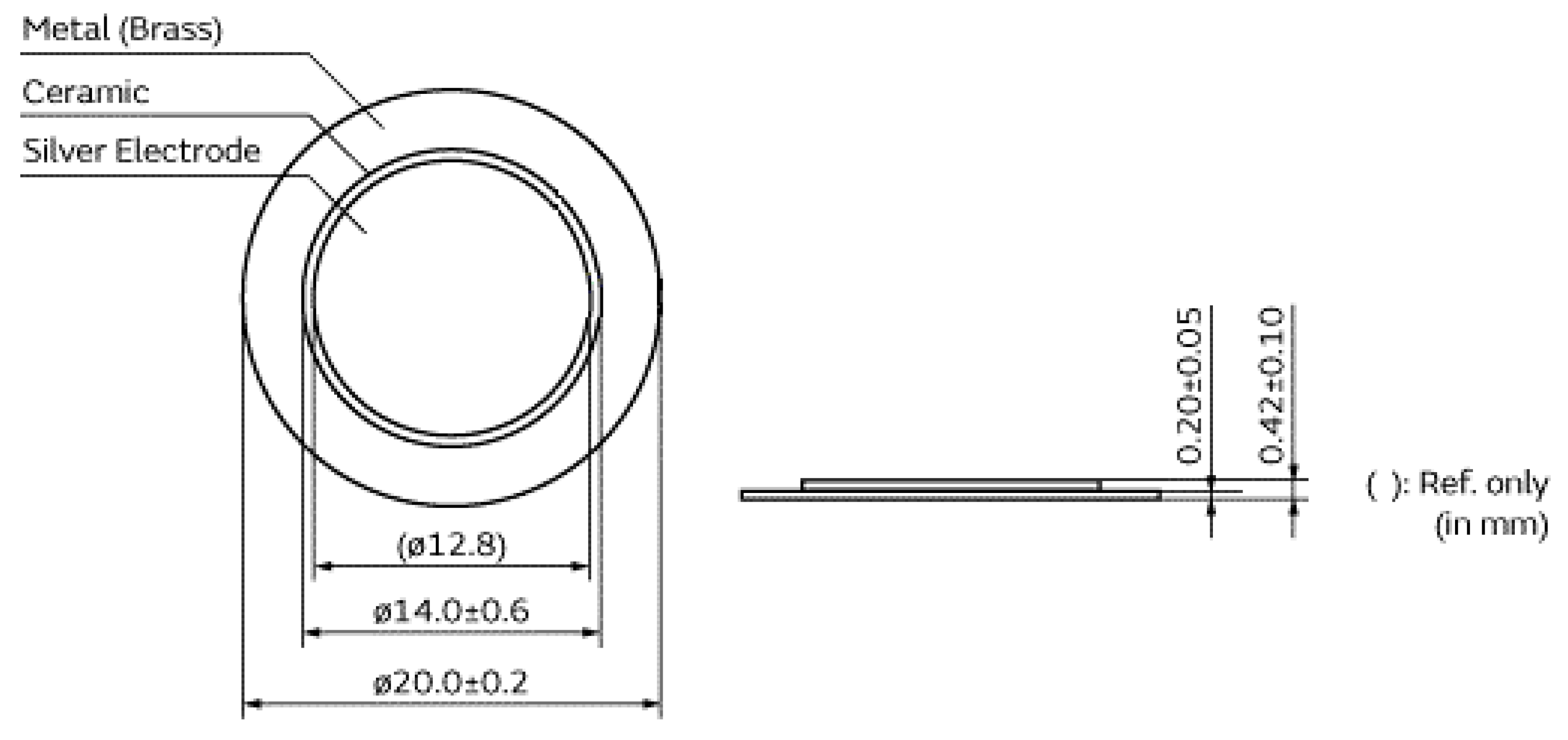
The specific transducers used in this study were piezoelectric diaphragms, which have similar characteristics to conventional PZT ceramics [
9,
10]. The buzzer diaphragms each have a circular brass plate whose dimensions are 20 mm × 0.2 mm that houses a circular piezoelectric ceramic with the dimensions 14 mm × 0.42 mm, which is coated by a metallic film, as shown in
Figure 1.
The PLB test is a well-known test in signal processing to determine the sensor frequency response, as seen in [
11,
12]. For the experimental setup used in this work, the cut-off frequency for the piezoelectric sensor was about 117 kHz, which is compatible with its application in vibration analysis (up to 20 kHz).
3. RMS Signal Processing Analysis Applied to Acoustic Emission and Vibration Signals
Traditionally, root mean square parameters have been an effective alternative to performing a vibration and acoustic signal characterization. This approach is directly related to the vibrational or acoustic load applied to the sensor, and is an attractive attribute for any monitoring application [
14]. Based on the formal definition of the RMS value, the RMS parameter for analysis of finite time AE signals is given by:
where in Equation (3),
is the period of the signal and
is the continuous time function that characterizes it. The equation for discrete samples is also described, where
is the number of samples and
is the value of the
n-th sample of the signal [
15].
4. Methods
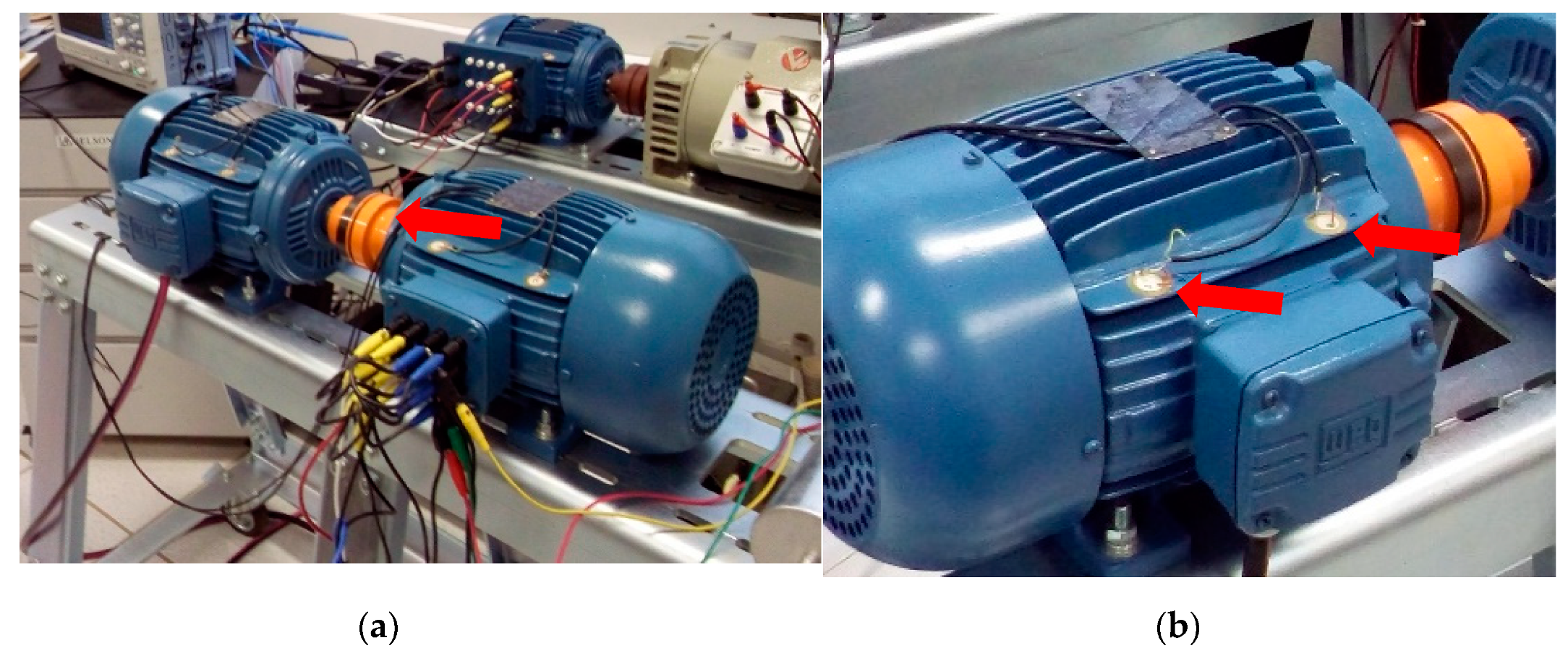
In order to verify the effectiveness of the piezoelectric diaphragm for TIM load estimation, two electrical machines were used to perform the tests: a TIM and an induction generator (IG). Both machines were fixed firmly on a bench and their shafts were coupled using a metal joint (
Figure 2a). The piezoelectric sensors were attached to the TIM, as shown in
Figure 2b. To simplify, this section is divided into two parts. The first part presents the TIM setup while the second part discusses the data acquisition systems and sensor validation setup.
4.1. TIM Setup
Once the machines were coupled, the TIM was powered at its nominal voltage by the three-phase source supply. The IG was used as a mechanical load and, for the first measurement, its output terminals were set as an open circuit, i.e., the initial loading corresponded only to the IG inertia. After this, a three-phase load bank was connected to the IG and set to increase the current value in steps of 0.5 A, starting at 0 A and increasing until it reached 12 A.
Each current value on the IG terminals represented a different loading demand on the TIM shaft, which meant that the current flowing through the TIM also varied. The software controlling the three-phase source also had a graphic interface where the motor current could be read. The loading value could be ascertained by comparing this information with the “current vs loading” curve presented in the datasheet provided by the TIM manufacturer. Later, the TIM loading was linked with the signals acquired by the low-cost sensors.
4.2. Sensor and Data Acquisition
Two piezoelectric diaphragms were attached to the front and back sides of the TIM using cyanoacrylate-based glue, as shown in
Figure 2b. Before the signals from the sensor could be acquired by the oscilloscope, they were amplified by an instrumentation amplifier (INA 128P—Texas
®) the frequency response of which is up to 400 kHz and the amplitude gain of which was set to 25. The oscilloscope sample rate was set to 1 MS/s, which satisfies the Nyquist theorem, since the cutoff frequency for these sensors is about 117 kHz, according to the PLB test. To avoid high-frequency interference, the resulting signals from the piezoelectric sensors were subjected to a 20 kHz low-pass filter and processed using MATLAB
® software. These results were presented and discussed in
Section 3.
The connection cables between the sensors and the amplifier board were shielded using a grounded mesh to avoid electromagnetic interference. The bench and the symmetrical DC source used to power the instrumentation board also needed to be grounded. In addition, to avoid temperature fluctuations, the TIM was brought to a steady state before any measurement, and, for loads greater than 100%, the tests were performed quickly.
5. Results and Discussion
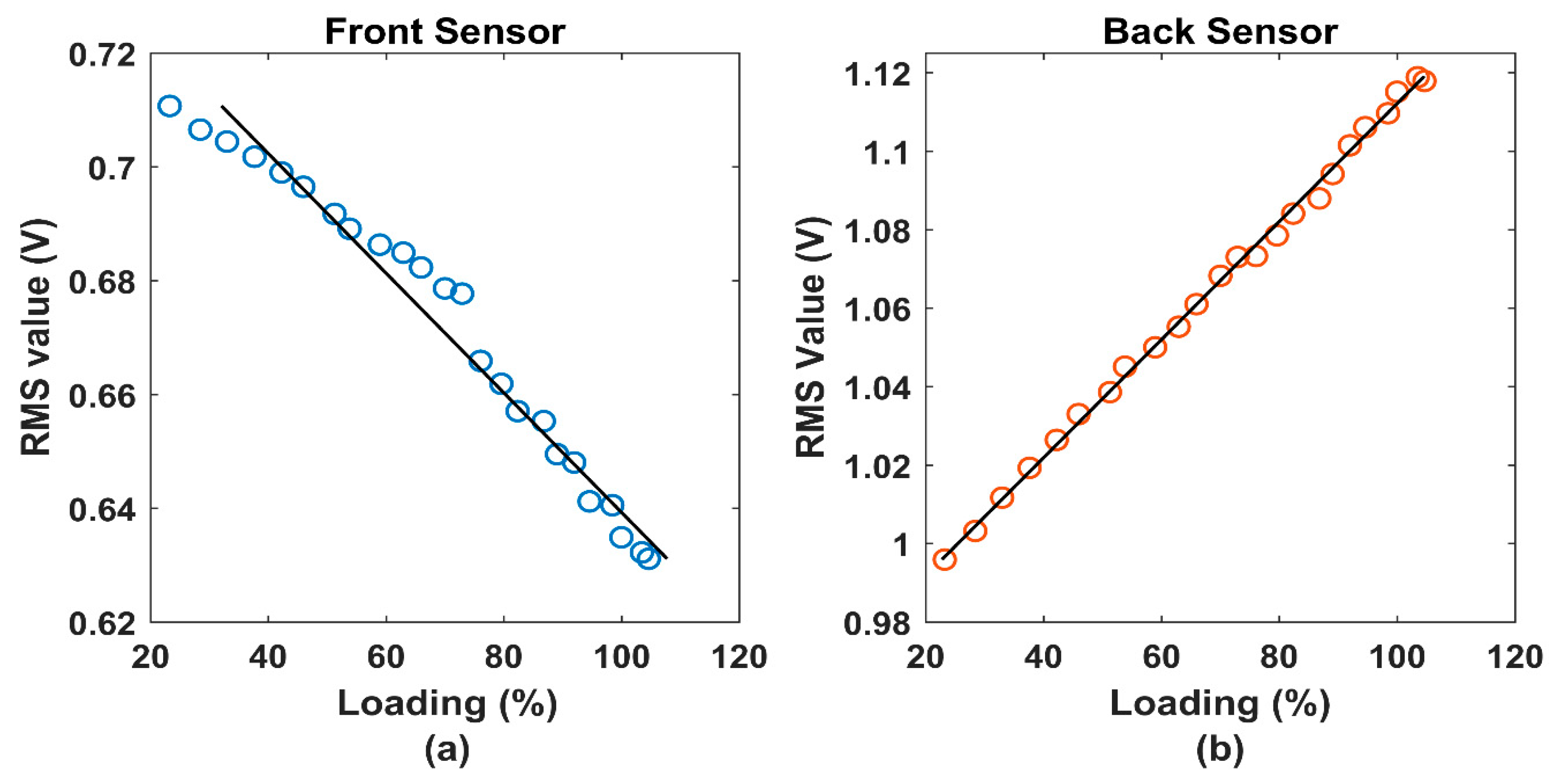
In order to evaluate the effectiveness of piezoelectric sensors for TIM load estimation, the RMS values were calculated for different types of TIM loading. The
Figure 3 shows the RMS curves for the front and back piezoelectric coupling.
As seen in
Figure 3a, for the front sensor, the RMS values decreased in a near-linear trend. This behavior showed that the coupling between the TIM and the load (IG) became tighter for higher loads, leading to lower levels of vibratory displacements in areas closer to the metal joint.
Consequently, as the loading decreased, the coupling became freer, increasing vibratory displacements.
Unlike the front coupling, the RMS values for the back sensor, presented in
Figure 3b, followed a directly proportional linear trend to the TIM loading. This behavior shows that areas further from the coupling between the machines were less affected by the phenomena seen on the front side of the TIM and tended to suffer higher vibratory displacements for higher loads.
Based on the linear behavior presented for both curves, as seen in
Table 1, a loading estimation using the RMS values and low-cost piezoelectric sensors can be achieved using simple linear regression. Considering the obtained results, it can be concluded that the piezoelectric sensor was able to diagnose the load pattern in the TIM.
6. Conclusions
This work evaluated a low-cost piezoelectric sensor as a transductor in vibrational analysis approaches to diagnosing and preventing failures in TIMs. For this purpose, we proposed an experimental setup where two sensors were attached to a TIM and the resulting signals for different loading levels were processed using the MATLAB® software.
The growing demand for cheaper and more reliable sensor-based systems, mainly for TIM fault detection and maintenance, justifies the study of applications based on piezoelectric sensors. Due the high commercial prices of prevailing devices, low-cost approaches establish a safer and more profitable industrial environment by promoting affordable solutions using NDT.
The results of the present study establish that piezoelectric sensors are capable of estimating TIM loading through a linear regression of their RMS curves. Additionally, the results indicated that oversized motors may show mechanical wear to their front components due to the higher vibratory oscillations caused by the free space observed in the coupling between the TIM and the load at lower loading values.
These first experimental results demonstrated that low-cost sensors have the potential to act as transducers in vibration analysis, therefore, in future studies it is feasible that these sensors could identify electrical and mechanical failures in TIMs. This is an initial experiment and more tests must be applied to these sensors for future validation.


