Abstract
Overexposure to hand-transmitted vibrations (HTVs) is a serious concern within industries that use vibrating power tools as HTVs can lead to severe and chronic injuries to the hand-arm system, which are preventable by limiting vibration exposure. This study presents a novel vibration-sensing electronic yarn (E-yarn) that can be used to monitor HTVs at the point-of-entry of the vibrations into the hand. The construction of the vibration-sensing E-yarn is described, with the vibration-sensing E-yarns being fully characterised at each stage of the manufacturing process to understand how the manufacturing stages affect the behaviour of the embedded sensor. The results show that there is no significant difference in the sensor response at each of the three stages in the E-yarn production over a range of frequencies and amplitudes relevant to HTVs.
1. Introduction
Overexposure to hand-transmitted vibrations (HTVs) can result in significant injuries to the neurological, vascular, and musculoskeletal systems [1,2], with the most common disorders arising being hand-arm vibration syndrome (more commonly referred to as vibration white finger) and carpal tunnel syndrome [1]. Significant vibration exposure can also result in tingling and numbness in the fingers, weakness in grip, and pain [3]. Such exposure to vibrations is prevalent in industries that use vibrating power tools and machinery, including the construction industry, mining [1], and the military.
There are a number of factors that influence the potential for injury, including vibration magnitude, frequency, and duration [4,5]. Limiting the exposure to vibrations can prevent the occurrence of these disorders, and research has shown that there is a latency in hand-arm vibration syndrome symptoms [6]. Therefore, by monitoring vibration exposure, overexposure and injury can be avoided.
This work proposes a solution for monitoring the exposure to vibration at the point-of-entry, which is usually the palm, by creating a vibration-sensing electronic yarn (E-yarn). The E-yarns are thin, soft, and conformable, which enable them to be embedded within a work glove without causing discomfort to the wearer. A prototype of this E-yarn has been reported in literature before and this work further develops the technology [7]. E-yarn technology has previously been successfully used for acoustic sensing [8] and temperature sensing [9].
The vibration-sensing E-yarns are created by soldering a microelectromechanical systems (MEMSs) accelerometer onto copper wire interconnections. The solder joints and MEMSs device are subsequently encapsulated within a resin micro-pod with embedded polyester carrier yarns. Finally, the ensemble is covered in a braided sheath. Using the MEMSs accelerometer in this way, and the inclusion of the different covering materials, could significantly affect the response of the sensor. It is therefore important to characterise the sensor’s response at different frequencies and amplitudes of vibration relevant to HTVs to ensure that the final E-yarns are appropriate for HTV monitoring, which is the purpose of this work.
2. Materials and Methods
2.1. Vibration-Sensing E-yarn Fabrication
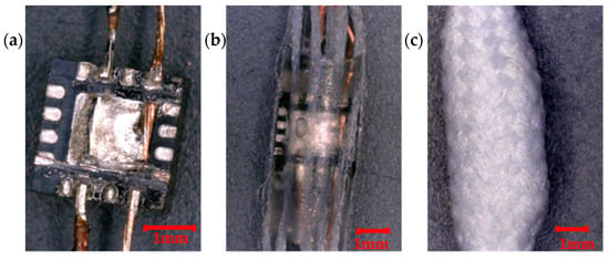
The vibration-sensing E-yarns were created by first soldering a 3-axis Micro-Electro-Mechanical Systems (MEMSs) accelerometer (ADXL337, Analog Devices, Norwood, MA, United States) onto multifilament copper wires using an infrared soldering process (PDR IR-R3 Rework System, PDR, Crawley, UK). The connected solder pads related to the Z-axis and X-axis output, the power (voltage in), and the ground. The power and ground wires used insulated copper wire (BXL2001, OSCO Ltd., Milton Keynes, UK) to isolate these wires from the X and Z outputs (which used a seven-strand copper wire with a 50 µm strand diameter; Knight Wire, Potters Bar, UK). The Y-axis output was not connected as the position of the solder pad made the construction of indicial vibration-sensing E-yarns difficult (see Figure 1a).

Figure 1.
Construction process for the vibration-sensing electronic yarns. (a) The accelerometer was soldered onto thin, multi-strand copper wires. (b) The solder joints, accelerometer, and polyester carrier yarns were encapsulated within a resin micro-pod. (c) The ensemble was covered in a braided sheath to create the final vibration-sensing E-yarn.
The accelerometer and solder joints where placed within a 3.3 mm diameter Teflon tube along with eight textured multifilament polyester yarns (Ashworth and Sons, Cheshire, UK), equally spaced around the chip. The tube was filled with curable polymer resin (Dymax, 9001-E-V3.7, Dymax, Corporation, Torrington, CT, USA) and exposed to a UV light source (BlueWaveTM 50, Dymax Corporation Torrington, CT, USA) until the resin has fully cured (see Figure 1b). The encapsulated accelerometer was inserted into a braiding machine (RU1/24-80, Herzog GmbH, Oldenburg, Germany) to create a final vibration-sensing E-yarn that was mechanically robust and had the appearance of a normal textile yarn (see Figure 1c).
2.2. Testing Procedure
A Brüel & Kjær Type 4810 small vibration stage (Brüel & Kjær, Nærum, Denmark) driven by a power amplifier (Type 2718; Brüel & Kjær) was used to induce vibrations in the yarns. A calibrated, cubic, tri-axial accelerometer (4520-001; Brüel & Kjær) and a signal analyser (Photon+, Brüel & Kjær) were used to record the amplitude and frequency of the induced vibrations. The RT Pro Photon software (Version 7.30.10; Brüel & Kjær) was used to control the vibration stage, collect data from the tri-axial accelerometer, and to collect data from the vibration-sensing E-yarns. Root mean square (RMS) values were recorded for both the induced vibrations and the vibration-sensing E-yarns.
The vibration-sensing E-yarns being tested were attached to the tri-axial accelerometer, which was attached to the top of the vibration stage. To ensure good adhesion between the vibration-sensing E-yarn and the tri-axial accelerometer, double-sided tape was used. The vibration-sensing E-yarns were powered using a benchtop variable power supply (ISO-TECH IPS3303 Digital Bench Power Supply, ISO-TECH, Southport, UK).
Frequency and amplitude dependence experiments were performed in both the Z-axis and X-axis orientations. The frequency dependence was measured using a fixed amplitude of 1 ms−2, at six frequencies: 8 Hz, 80 Hz, 125 Hz, 250 Hz, 800 Hz, 1250 Hz, and 2000 Hz, while the amplitude dependence was measured at five different amplitudes: 10 ms−2, 5 ms−2, 2.5 ms−2, 1 ms−2, and 0.5 ms−2 for three frequencies: 80 Hz, 800 Hz, and 1250 Hz.
All data presented show the average of four separate yarns with the corresponding error bars given by the standard deviation. The figures presented in the work were prepared using IGOR Pro (Version 7.0.2.2; Wavemetrics, Lake Oswego, OR, USA).
3. Results
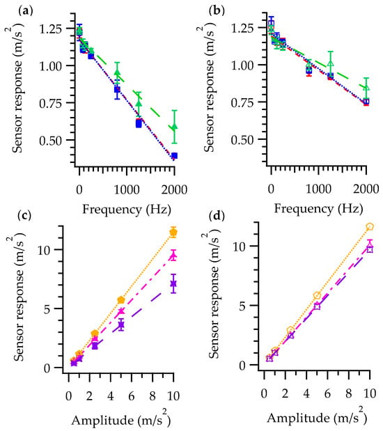
Figure 2 shows the effect of the manufacturing process on the frequency and amplitude response of the embedded accelerometer at different stages in the manufacturing process.

Figure 2.
Effect of the E-yarn manufacturing process on the accelerometer response. (a) Frequency response in the Z-axis. Soldered stage  ; encapsulated stage
  ; the final E-yarn
  . (b) The frequency response in the X-axis. Soldered stage
  ; encapsulated stage
  ; the final E-yarn
  . (c) The amplitude response for the different frequencies in the Z-axis. 80 Hz
  ; 800 Hz
  ; 1250 Hz
  . (d) The amplitude response for the different frequencies in the X-axis. 80 Hz
  ; 800 Hz
  ; 1250 Hz
  .
.
The results show a clear linear relationship between the sensor response and the frequency in both the Z-axis and X-axis. There was no significant difference in the sensor response between the soldering stage and the encapsulation stage, however, a slight difference was observed at higher frequencies once the braid was added. Figure 2c,d show the amplitude dependence for the final vibration-sensing E-yarns in the Z-axis (Figure 2c) and X-axis (Figure 2d). The results show that there was a linear relationship with amplitude. However, this was different for each frequency. Additionally, the Z-axis and X-axis responses were different. Despite the observed differences between the Z-axis and X-axis, this data could be used to calibrate readings recorded from the vibration-sensing E-yarns and provide an accurate output.
4. Conclusions
This work presents a vibration-sensing E-yarn designed to monitor hand-transmitted vibrations (HTVs). The linearity of the vibration-sensing E-yarn’s response to changes in vibration amplitude at the different frequencies has been confirmed. The response relationships can be used to calibrate the response from the vibration-sensing E-yarn to determine vibrations. Multiple yarns were compared, showing that each behaved in a similar fashion. This validates the use of this type of vibration-sensing E-yarn for HTV measurements.
Author Contributions
Conceptualization, T.H.-R. and T.D.; investigation, Z.R.; writing—original draft preparation, Z.R. and T.H.-R.; writing—review and editing, Z.R., T.H.-R., and T.D.
Funding
This research received no external funding.
Acknowledgments
The authors would like to thank Nottingham Trent University Health and Wellbeing Proof of Concept Fund for providing funding towards this research. The authors would like to thank Carlos Oliveira for assistance in making the E-yarns.
Conflicts of Interest
The authors declare no conflict of interest.
References
- Milosevic, M.; McConville, K.M.V. Measurement of vibrations and evaluation of protective gloves for work with hand-held power tools in industrial settings. Conf. Proc. IEEE Eng. Med. Biol. Soc. 2007, 2007, 2281–2284. [Google Scholar]
- Shen, S.C.; House, R.A. Hand-arm vibration syndrome: What family physicians should know. Can. Fam. Physician 2017, 63, 206–210. [Google Scholar] [PubMed]
- Le, B.E.R.; Ay, Y.; Ayers, B. An Interpretative Phenomenological Analysis of the Psychological Ramifications of Hand-Arm Vibration Syndrome. J. Heal. Psychol. 2010, 15, 533–542. [Google Scholar]
- Maeda, S.; Taylor, M.D.; Anderson, L.C.; McLaughlin, J. Determination of hand-transmitted vibration risk on the human. Int. J. Ind. Ergon. 2019, 70, 28–37. [Google Scholar] [CrossRef]
- Griffin, M.J. Measurement, evaluation, and assessment of occupational exposures to hand-transmitted vibration. Occup. Environ. Med. 1997, 54, 73–89. [Google Scholar] [CrossRef] [PubMed]
- Miyashita, K.; Shiomi, S.; Itoh, N.; Kasamatsu, T.; Iwata, H. Epidemiological study of vibration syndrome in response to total hand-tool operating time. Br. J. Ind. Med. 1983, 40, 92–98. [Google Scholar] [CrossRef] [PubMed]
- Hughes-Riley, T.; Dias, T. The development of acoustic and vibration sensing yarns for health surveillance. In Proceedings of the 25th International Congress on Sound and Vibration (ICSV25), Hiroshima, Japan, 8–12 July 2018. [Google Scholar]
- Hughes-Riley, T.; Dias, T. Developing an Acoustic Sensing Yarn for Health Surveillance in a Military Setting. Sensors 2018, 18. [Google Scholar] [CrossRef] [PubMed]
- Hughes-Riley, T.; Lugoda, P.; Dias, T.; Trabi, C.L.; Morris, R.H. A Study of Thermistor Performance within a Textile Structure. Sensors 2017, 17, 1804. [Google Scholar] [CrossRef] [PubMed]
Publisher’s Note: MDPI stays neutral with regard to jurisdictional claims in published maps and institutional affiliations. |
© 2019 by the authors. Licensee MDPI, Basel, Switzerland. This article is an open access article distributed under the terms and conditions of the Creative Commons Attribution (CC BY) license (https://creativecommons.org/licenses/by/4.0/).