Overcoming the Efficiency Barrier of Textile Antennas: A Transmission Lines Approach †


Abstract
:1. Introduction
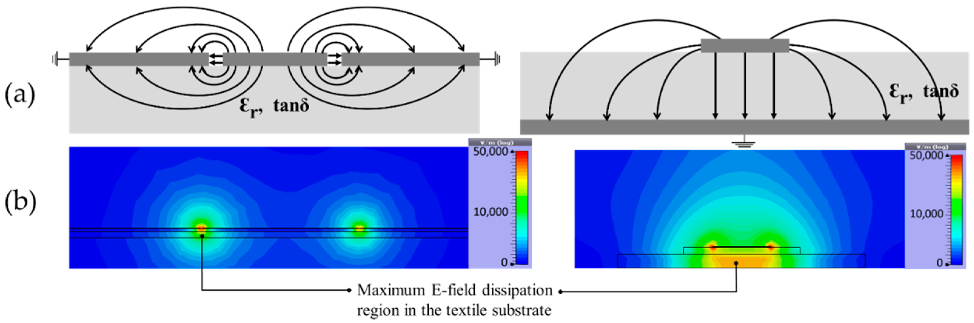
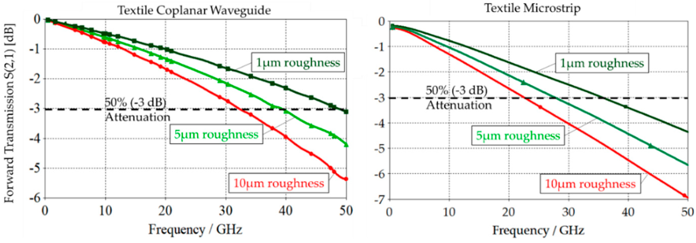
2. Characterising and Analysing Textile Transmission Lines
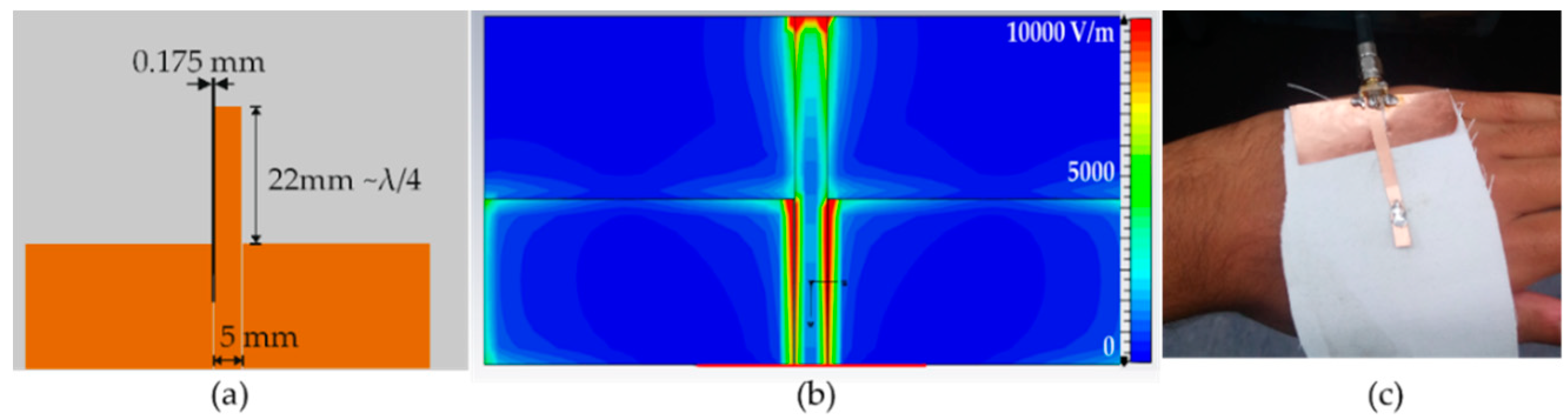
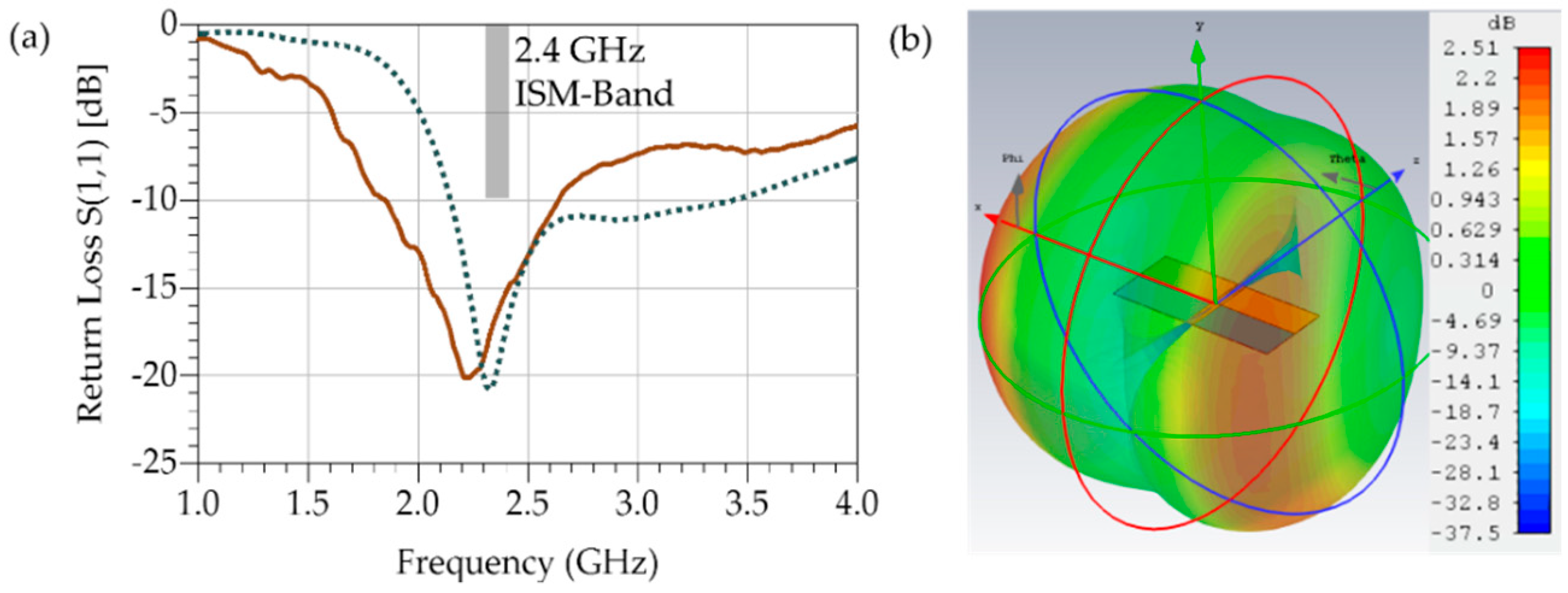
3. The Coplanar-Wave Guide Monopole Antenna
4. Conclusions
Author Contributions
Funding
Conflicts of Interest
References
- Corchia, L.; Monti, G.; Tarricone, L. Wearable Antennas: Nontextile Versus Fully Textile Solutions. IEEE Antennas Propag. Mag. 2019, 61, 71–83. [Google Scholar] [CrossRef]
- Whittow, W.G.; Chauraya, A.; Vardaxoglou, J.C.; Li, Y.; Torah, R.; Yang, K.; Beeby, S.; Tudor, J. Inkjet-Printed Microstrip Patch Antennas Realized on Textile for Wearable Applications. IEEE Antennas Wirel. Propag. Lett. 2014, 13, 71–74. [Google Scholar] [CrossRef]
- Wagih, M.; Wei, Y.; Beeby, S. Flexible 2.4 GHz Node for Body Area Networks with a Compact High-Gain Planar Antenna. IEEE Antennas Wirel. Propag. Lett. 2018, 18, 49–53. [Google Scholar] [CrossRef]
- Adami, S.E.; Proynov, P.; Hilton, G.S.; Yang, G.; Zhang, C.; Zhu, D.; Li, Y.; Beeby, S.P.; Craddock, I.J.; Stark, B.H. A Flexible 2.45-GHz Power Harvesting Wristband with Net System Output from −24.3 dBm of RF Power. IEEE Trans. Microw. Theory Tech. 2017, 66, 380–395. [Google Scholar] [CrossRef]
- Wagih, M.; Weddell, A.S.; Beeby, S. Millimeter-Wave Textile Antenna for On-Body RF Energy Harvesting in Future 5G Networks. In Proceedings of the IEEE Wireless Power Transfer Conference, London, UK, 18–21 June 2019. [Google Scholar]
- Rotaru, M.D.; Wagih, M.A. Analysis and Design of Low-Loss Differential Transmission Line Structures for High Speed Applications. In Proceedings of the IEEE 19th Electronic Packaging Technology Conference, Singapore, 6–9 December 2017. [Google Scholar]
- Declercq, F.; Rogier, H.; Hertleer, C. Permittivity and Loss Tangent Characterization for Garment Antennas Based on a New Matrix-Pencil Two-Line Method. IEEE Trans. Antennas Propag. 2008, 56, 2548–2554. [Google Scholar] [CrossRef]


| This Work | Whittow et al. (2014) [2] | Adami et al. (2018) [4] | |
|---|---|---|---|
| Antenna Design | CPW Monopole | Microstrip Patch | Microstrip Patch |
| Conductor | Cu Polyimide Laminate | Inkjet-Printed Silver Ink | Copper-Coated Fabric |
| Substrate | 0.3 mm Poly-cotton (tanδ = 0.028) | 0.2 mm Woven-Polyester + 1.4 mm Felt (tanδ = 0.023) | 3.2 mm Felt (tanδ = 0.028) |
| Return Loss, S11 (dB) | −20.1 | −9 | −26 |
| Fractional Bandwidth | 35% | 0.58% | 4.1% |
| Radiation Efficiency | 86% * | 37% | 73% |
| Gain (dB) | 2.51 * | 4.02 | 8.1 |
Publisher’s Note: MDPI stays neutral with regard to jurisdictional claims in published maps and institutional affiliations. |
© 2019 by the authors. Licensee MDPI, Basel, Switzerland. This article is an open access article distributed under the terms and conditions of the Creative Commons Attribution (CC BY) license (https://creativecommons.org/licenses/by/4.0/).
Share and Cite
Wagih, M.; Weddell, A.S.; Beeby, S. Overcoming the Efficiency Barrier of Textile Antennas: A Transmission Lines Approach. Proceedings 2019, 32, 18. https://doi.org/10.3390/proceedings2019032018
Wagih M, Weddell AS, Beeby S. Overcoming the Efficiency Barrier of Textile Antennas: A Transmission Lines Approach. Proceedings. 2019; 32(1):18. https://doi.org/10.3390/proceedings2019032018
Chicago/Turabian StyleWagih, Mahmoud, Alex S. Weddell, and Steve Beeby. 2019. "Overcoming the Efficiency Barrier of Textile Antennas: A Transmission Lines Approach" Proceedings 32, no. 1: 18. https://doi.org/10.3390/proceedings2019032018
APA StyleWagih, M., Weddell, A. S., & Beeby, S. (2019). Overcoming the Efficiency Barrier of Textile Antennas: A Transmission Lines Approach. Proceedings, 32(1), 18. https://doi.org/10.3390/proceedings2019032018