Abstract
This paper proposes a new thermal contact resistance measurement method using lock-in thermography. By the lock-in thermography with an infrared microscope, the dynamic temperature behavior across the contact interface was visualized in the sample side surface. Meanwhile, a new thermal contact resistance measurement principle was constructed by the superimposition of the temperature wave from virtual heat sources in consideration of the thermal contact resistance at the interface. Consequently, the thermal contact resistance was obtained as a fitting parameter by fitting the theoretical curve to the measured amplitude and phase lag. The validity of the principle was shown.
1. Introduction
The thermal contact resistance (TCR) is a phenomenon that the heat flow is impeded at the contact interface between two materials. Reduction of TCR is the issue for efficiently discharging heat waste of electronics. However, the prediction theory of TCR in a non-ideal contact interface, which contains various TCR factors, is not established. In terms of TCR measurement, the steady state method is generally used to measure the comprehensive TCR across the contact interface of the bulk sample. Additionally, as unsteady methods, the thermo-reflectance [1] method and the 3 ω method [2,3] are studied to measure TCR of the homogenous thin film sample. However, the method to measure the local TCR in the contact interface is not established. The local TCR measurement is important to evaluate the relationship between the TCR phenomenon and TCR factors; geometrical one, mechanical one and material depended one. This paper proposes a new local TCR measurement method by a periodic heating method. Besides, the validity of the method is confirmed. The dynamic temperature wave behavior at the contact interface in micro scale was visualized using a lock-in thermography (LIT) with an infrared microscope. Furthermore, TCR was estimated by fitting the theoretical curve of the amplitude and the phase lag of the temperature wave to the measurement plots. It was shown that the local contact resistance can be evaluated by using this method.
2. Measurement Theory
The measurement method is discussed on the two layers system consisted of two thin plates A and B that have TCR at their interface, as shown in Figure 1. When the edge of the A layer surface is heated periodically by a laser focused in a spot, the temperature wave from the heat source reflects and transmits repeatedly at the sample surfaces and the contact interface [4]. Temperature response is expressed by the mirror images method. In the method temperature response is obtained by the superimposition of the elementary temperature wave which propagate in the infinite medium from the virtual heat source in consideration of the reflectance and transmittance. Then, temperature response is expressed as following:

Figure 1.
Schematic of TCR measurement theory.
when n = 2m + 1 (),
when n = 2m (),
T is the temperature, the subscribe A, B represents layer A and B, r is the distance in thickness direction, t is time, T0 is the temperature normalization constant, n is the number of the reflectance and transmittance, d is the thickness, is the complex wave number; , ω is the angular frequency, D is the thermal diffusivity, γn and τn are the reflectance and transmittance coefficient of the temperature wave at contact interface with TCR. γn and τn are derived from two thermal interfacial condition, the temperature jump caused by TCR and the heat flux continuity. They are expressed as following:
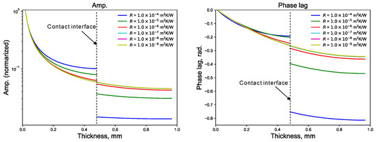
λ is the thermal conductivity. The sample surface and the back surface are assumed to be insulated. From Equations (1) and (2), the amplitude and the phase lag of the temperature wave along r from the heating point is obtained. At the contact interface (r = d), the amplitude and the phase lag jump depending on only TCR when the thermal diffusivity and the thermal conductivity of the A and B layer is known. Figure 2 shows Theoretical curve of the amplitude and the phase lag for the different thermal contact resistances (denoted by R). Therefore, TCR is obtained by fitting the theoretical amplitude and phase lag to the plots measured by LIT.

Figure 2.
Theoretical curve of amplitude and phase lag for different thermal contact resistance.
3. Measurement Apparatus
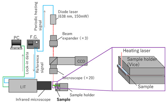
The measurement apparatus is shown in Figure 3 and it is consisted of a diode laser (638 nm), an objective lens to focus the laser beam in a spot, LIT device with the infrared microscope, a function generator to oscillate periodic signal, a PC to conduct lock-in analysis. A sample was made by the bonding and lamination for two isotropic graphite IG-110 plate (thickness is 0.480 mm). The total thickness of the prepared sample was 0.965 mm. Therefore, the thickness of the bonding layer is estimated to be about 5 μm. The thermal conductivity and the thermal diffusivity of IG-110 are 126 W/(m⋅K) and 102 × 10−6 m2/s [5]. TCR measurements were conducted in the conditions of 1 Hz and 20 Hz to confirm the influence of the heating frequency to the results.

Figure 3.
Schematic of TCR measurement apparatus.
4. Discussion
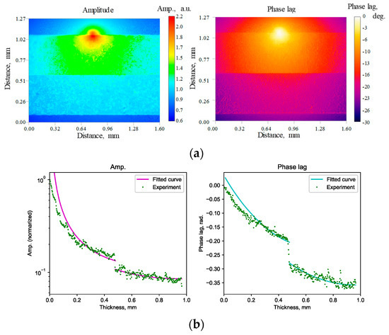
The contour of the Figure 4a shows the amplitude and the phase lag distribution obtained by lock-in analysis in the 1 Hz heating measurement. It is confirmed that the amplitude and the phase lag have discontinuity and jumps at the contact interface. Incidentally, the distribution spread above the sample surface indicate the temperature response of the atmosphere excited by the sample heating. The plots and curve of Figure 4b show the fitted theoretical curve and the measurement plots. Although the curve and plots show good agreement, the difference becomes greater near the heat source. This is caused by the difference of the heat source size between the measurement theory and the actual apparatus That is, the diameter of the actual heat source is finite, while theoretical heat source is a spot. However, this difference can be negligible according to being away from the heat source. Table 1 lists the results of the fitting analysis of the amplitude and the phase lag in 1 Hz and 20 Hz heating.

Figure 4.
Amplitude and phase lag distribution and fitting analysis for TCR. (a) Amplitude and phase lag distribution in 1 Hz and 20 Hz heating. (b) Fitting results for amplitude and phase plag in 1 Hz and 20 Hz heating.

Table 1.
Results of fitting analysis of amplitude and phase lag in 1 Hz and 20 Hz heating.
Table 1 shows the good agreement of the TCR on 10−6 m2 K/W order among measurement conditions of the amplitude fitting, the phase lag fitting and heating frequencies. However, the difference of the results is greater in the amplitude fitting than the phase lag one, because the amplitude is more susceptible for the difference of the heat source size discussed before. That is, the difference of the amplitude becomes infinite at the heat source. Besides, the difference of the results is greater in the 1 Hz measurement than 20 Hz one, because the lower frequency measurement is more susceptible for the difference of the heat source due to becoming thermally close to the heat source for its longer thermal diffusion length. The validity of the measurement is also confirmed by the thermal resistance in the bonding layer, around 5 × 10⁻⁶ to 5 × 10⁻⁵ m2 K/W, estimated from the thickness of the bonding layer, about 5 μm, and the thermal conductivity of the bisphenol-A type epoxy adhesive, around 0.1 W/(m⋅K) to 1 W/(m⋅K). However, the target value of TCR in this study is 1 × 10⁻⁹ to 1 × 10⁻⁷ m2 K/W in terms of the evaluation of the relationship between the TCR phenomenon and the TCR factors. Therefore, the validity of the measurement in lower the TCR contact interface, 1 × 10⁻⁹ to 1 × 10⁻⁷ m2 K/W, will be confirmed in the future.
5. Conclusions
A new TCR measurement method was proposed. First, the periodic heating measurement theory derived by the method of mirror images was shown. Then, using the LIT device with infrared microscope, the behavior of the amplitude and the phase lag of the temperature wave throw the contact interface was observed. Consequently, it was confirmed that the amplitude and the phase lag jump at the contact interface. Finally, TCR was evaluated by the fitting analysis of the theoretical amplitude and phase lag and measurement ones. Hence, the validity of the measurement was confirmed.
6. Patents
Japanese patent is going to be certified resulting from this work: JP2019−094934.
Funding
A part of this research was funded by JST CREST, grant number JPMJCR12I2.
Conflicts of Interest
The authors declare no conflict of interest.
References
- Hopkins, P.E.; Baraket, M.; Barnat, E.V.; Beechem, T.E.; Kearney, S.P.; Duda, J.C.; Robinson, J.T.; Walton, S.G. Manipulating Thermal Conductance at Metal−Graphene Contacts via Chemical Functionalization. Nano Lett. 2012, 12, 590–595. [Google Scholar] [CrossRef] [PubMed]
- Moridi, A.; Zhang, L.; Liu, W.; Duvall, S.; Brawley, A.; Jiang, Z.; Yang, S.; Li, C. Characterization of high thermal conductivity thin−film substrate systems and their interface thermal resistance. Surf. Coat. Technol. 2018, 334, 233–242. [Google Scholar] [CrossRef]
- Cahill, D.G.; Goodson, K.; Majumdar, A. Thermometry and Thermal Transport in Micro/Nanoscale Solid-State Devices and Structures. J. Heat Transfer 2002, 124, 223–241. [Google Scholar] [CrossRef]
- Bertolotti, M.; Liakhou, G.L.; Li, V.R.; Paoloni, S.; Sibilia, C. Thermal Wave Reflection and Refraction: Theoretical and Experimental Evidence. J. Appl. Phys. 1999, 85, 3540–3545. [Google Scholar] [CrossRef]
- NMIJ Certified Reference Materials Catalog 2017–2018. Available online: https://www.nmij.jp/service/C/-CRM_Catalog_(JE)_2017-2018.pdf (accessed on 14 April 2019).
© 2019 by the authors. Licensee MDPI, Basel, Switzerland. This article is an open access article distributed under the terms and conditions of the Creative Commons Attribution (CC BY) license (https://creativecommons.org/licenses/by/4.0/).