Sensitivity Analysis of Fiber-Matrix Interface Parameters in an SMC Composite Damage Model †


Abstract
:1. Introduction
2. Continuum Mechanical Model
2.1. Fundamentals
2.2. Effective Behavior
2.3. Matrix Damage
2.4. Fiber-Matrix Interface Debonding
3. Fiber-Matrix Interface Parameters
3.1. Variation of
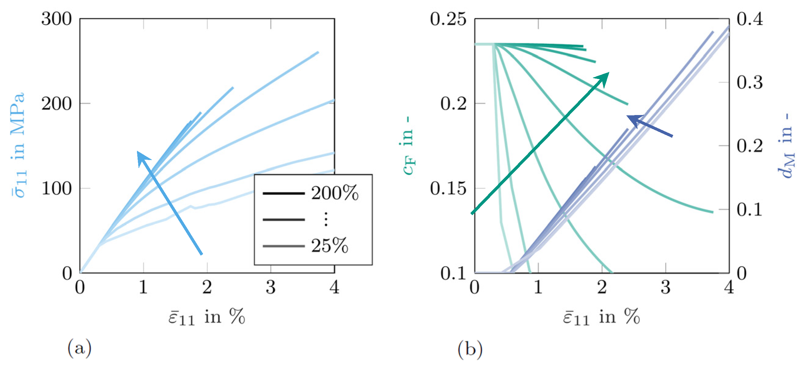
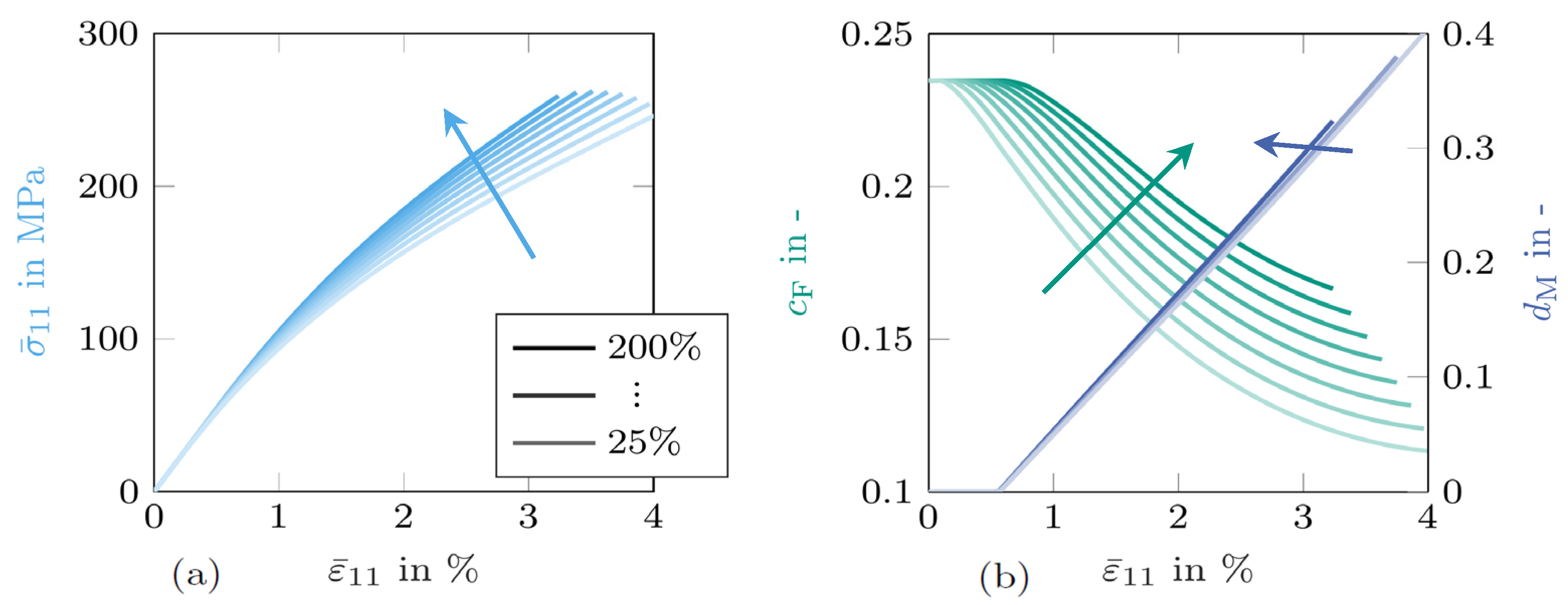
3.2. Variation of
3.3. Variation of
4. Conclusions
Author Contributions
Acknowledgments
Conflicts of Interest
References
- Schemmann, M.; Görthofer, J.; Seelig, T.; Hrymak, A.; Böhlke, T. Anisotropic meanfield modeling of debonding and matrix damage in SMC composites. Compos. Sci. Technol. 2018. [Google Scholar] [CrossRef]
- Meraghni, F.; Benzeggagh, M.L. Micromechanical modelling of matrix degradation in randomly oriented discontinuous-fibre composites. Compos. Sci. Technol. 1995, 55, 171–186. [Google Scholar] [CrossRef]
- Jendli, Z.; Meraghni, F.; Fitoussi, J.; Baptiste, D. Micromechanical analysis of strain rate effect on damage evolution in sheet molding compound composites. Compos. Part A Appl. Sci. Manuf. 2004, 35, 779–785. [Google Scholar] [CrossRef]
- Ben Cheikh Larbi, A.; Sai, K.; Sidhom, H.; Baptiste, D. Constitutive Model of Micromechanical Damage to Predict Reduction in Stiffness of a Fatigued SMC Composite. J. Mater. Eng. Perform. 2006, 15, 575–580. [Google Scholar] [CrossRef]
- Fitoussi, J.; Bocquet, M.; Meraghni, F. Effect of the matrix behavior on the damage of ethylene-propylene glass fiber reinforced composite subjected to high strain rate tension. Compos. Part B Eng. 2013, 45, 1181–1191. [Google Scholar] [CrossRef]
- Favre, J.P.; Jacques, D. Stress transfer by shear in carbon fibre model composites—Part 1 Results of single-fibre fragmentation tests with thermosetting resins. J. Mater. Sci. 1990, 25, 1373–1380. [Google Scholar] [CrossRef]
- Koyanagi, J.; Nakatani, H.; Ogihara, S. Comparison of glass-epoxy interface strengths examined by cruciform specimen and single-fiber pull-out tests under combined stress state. Compos. Part A Appl. Sci. Manuf. 2012, 43, 1819–1827. [Google Scholar] [CrossRef]
- Shirinbayan, M.; Fitoussi, J.; Meraghni, F.; Surowiec, B.; Bocquet, M.; Tcharkhtchi, A. High strain rate visco-damageable behavior of Advanced Sheet Molding Compound (A-SMC) under tension. Compos. Part B Eng. 2015, 82, 30–41. [Google Scholar] [CrossRef]
- Yang, W.; Pan, Y.; Pelegri, A.A. Multiscale modeling of matrix cracking coupled with interfacial debonding in random glass fiber composites based on volume elements. J. Compos. Mater. 2012, 47, 3389–3399. [Google Scholar] [CrossRef]
- Fitoussi, J.; Guo, G.; Baptiste, D. A statistical micromechanical model of anisotropic damage for S.M.C. composites. Compos. Sci. Technol. 1998, 58, 759–763. [Google Scholar] [CrossRef]
- Derrien, K.; Fitoussi, J.; Guo, G.; Baptiste, D. Prediction of the effective damage properties and failure properties of nonlinear anisotropic discontinuous reinforced composites. Comput. Methods Appl. Mech. Eng. 2000, 185, 93–107. [Google Scholar] [CrossRef]
- Desrumaux, F.; Meraghni, F.; Benzeggagh, M.L. Generalised Mori-Tanaka Scheme to Model Anisotropic Damage Using Numerical Eshelby Tensor. J. Compos. Mater. 2001, 35, 603–624. [Google Scholar] [CrossRef]
- Lee, H.K.; Simunovic, S. A damage constitutive model of progressive debonding in aligned discontinuous fiber composites. Int. J. Solids Struct. 2001, 38, 875–895. [Google Scholar] [CrossRef]
- Ju, J.W.; Lee, H.K. A micromechanical damage model for effective elastoplastic behavior of ductile matrix composites considering evolutionary complete particle debonding. Comput. Methods Appl. Mech. Eng. 2000, 183, 201–222. [Google Scholar] [CrossRef]
- Zaïri, F.; Naït-Abdelaziz, M.; Gloaguen, J.M.; Bouaziz, A.; Lefebvre, J.M. Micromechanical modelling and simulation of chopped random fiber reinforced polymer composites with progressive debonding damage. Int. J. Solids Struct. 2008, 45, 5220–5236. [Google Scholar] [CrossRef]
- Fitoussi, J.; Guo, G.; Baptiste, D. Determination of a tridimensional failure criterion at the fibre/matrix interface of an organic-matrix/discontinuous-reinforcement composite. Compos. Sci. Technol. 1996, 56, 755–760. [Google Scholar] [CrossRef]
- Benveniste, Y.; Dvorak, G.J.; Chen, T. On diagonal and elastic symmetry of the approximate effective stiffness tensor of heterogeneous media. J. Mech. Phys. Solids 1991, 39, 927–946. [Google Scholar] [CrossRef]
- Castaneda, P.P.; Suquet, P. Nonlinear Composites. Adv. Appl. Mech. 1998, 34, 172–195. [Google Scholar] [CrossRef]
- Duschlbauer, D.; Pettermann, H.E.; Böhm, H.J. Mori-Tanaka based evaluation of inclusion stresses in composites with nonaligned reinforcements. Scr. Mater. 2003, 48, 223–228. [Google Scholar] [CrossRef]
- Weibull, W. A statistical distribution function of wide applicability. J. Appl. Mech. 1951, 18, 293–297. [Google Scholar] [CrossRef]
- Swentek, I.N. On the Interfacial Fracture Mechanics of Long- fibre Reinforced Polymer Composites. Ph.D. Thesis, The University of Western Ontario, London, ON, Canada, 2014. [Google Scholar]

Publisher’s Note: MDPI stays neutral with regard to jurisdictional claims in published maps and institutional affiliations. |
© 2018 by the authors. Licensee MDPI, Basel, Switzerland. This article is an open access article distributed under the terms and conditions of the Creative Commons Attribution (CC BY) license (https://creativecommons.org/licenses/by/4.0/).
Share and Cite
Görthofer, J.; Schemmann, M.; Seelig, T.; Hrymak, A.; Böhlke, T. Sensitivity Analysis of Fiber-Matrix Interface Parameters in an SMC Composite Damage Model. Proceedings 2018, 2, 544. https://doi.org/10.3390/ICEM18-05438
Görthofer J, Schemmann M, Seelig T, Hrymak A, Böhlke T. Sensitivity Analysis of Fiber-Matrix Interface Parameters in an SMC Composite Damage Model. Proceedings. 2018; 2(8):544. https://doi.org/10.3390/ICEM18-05438
Chicago/Turabian StyleGörthofer, Johannes, Malte Schemmann, Thomas Seelig, Andrew Hrymak, and Thomas Böhlke. 2018. "Sensitivity Analysis of Fiber-Matrix Interface Parameters in an SMC Composite Damage Model" Proceedings 2, no. 8: 544. https://doi.org/10.3390/ICEM18-05438
APA StyleGörthofer, J., Schemmann, M., Seelig, T., Hrymak, A., & Böhlke, T. (2018). Sensitivity Analysis of Fiber-Matrix Interface Parameters in an SMC Composite Damage Model. Proceedings, 2(8), 544. https://doi.org/10.3390/ICEM18-05438