1. Introduction
Fiber-reinforced composite materials have higher specific strength and specific modulus and good designable performance. They have been widely used in the defense industry as well as in the fields of construction, chemical engineering and transportation. It is an indispensable special engineering material for aerospace field. Impact loads are a main problem for composite material structures. Composite materials are more sensitive to impact loads than metal materials. The failure modes and failure mechanisms under dynamic load are very different from those under static conditions due to the strain rate effect [
1].
Bolted joint is a one of most used way to connect composite structures. The stress concentration around the holes will be more serious than metal structures because the bolt holes cut off the fibers. Therefore, it is necessary to analysis the composite bolted structure and to predict connection strength.
Winter [
2] discussed the effects of various variables such as plate thickness and bolt margins on the performance of joints by testing approach. Kim et al. [
3] studied the optimal design of bolted joints with carbon fiber/epoxy resin and glass fiber/epoxy under tensile load. Using finite element software to establish a three-dimensional model, the mechanical properties of the joints were simulated. The model could predict the first peak load due to delamination but failed to predict the failure strength. Ireman [
4] established a three-dimensional finite element model to describe the composite bolted joints and calculated the stress distribution at the edge of bolt hole. The simulation results were basically consistent with the experimental data. The errors were mainly due to the friction coefficient. Ger et al. [
5] conducted a dynamic tensile test on a carbon fiber/epoxy laminated plate bolt joint. They found that the strength of the bolt joint was lower than that under quasi-static load when the loading speed was 5 m/s. Due to differences in test methods, equipment, and data processing methods, as well as differences in properties of composite materials and geometries of bolt joints, the research conclusions on the failure modes, energy absorption, and strain rate effects of joints under dynamic loading are inconsistent. So it is necessary to establish an accurate finite element model to analyze the dynamic mechanical properties of the composite bolt joint.
2. Nonlinear Progressive Damage Model
A progressive failure model is developed to simulate the failure of composite single-bolted joint, the proposed damage model is applied to a 3D solid element by using ABAQUS/Explicit with VUMAT to analyze the intralaminar failure behavior for composites.
X850/QY8911 is used in this study. The material properties are obtained from experiments in our lab. E11t = 225.6 Gpa, E11c = 178.6 Gpa, E22t = 15.5 Gpa, E22c = 6.71 Gpa, G12 = 6.335 Gpa, G23 = 3.0 Gpa, G13 = 4.857 Gpa, ν12 = 0.334, ν23 = 0.599, ν13 = 0.334, Xt = 2707.4 Mpa, Xc = 1254.4 Mpa, Yt = 19.898 Mpa, Yt = 212.0 Mpa, S12 = 80.0 Mpa, S13 = 97.77 Mpa, S23 = 97.77 Mpa, ρ = 1500 kg/m3.
In this study, we adopt the Hashin damage failure criteria to predict composite damage. Hashin damage failure criteria consider the four typical failure modes under dynamic loading, including fiber breakage, fiber extrusion, matrix cracking and matrix cracking for in-plane damage of unidirectional laminates.
When local failure occurs in the composite laminate, the corresponding material point is subjected to a reduction in stiffness. Different stiffness degradation methods are used to consider the effect of different failure modes on the mechanical properties of laminates. This study adopt the stiffness degradation model proposed by Tan [
6], as shown in
Table 1.
3. Quasi-Static Model
To validate the numerical model, corresponding quasi-static tensile experiments of carbon–epoxy composite plates with single-bolted joint were conducted by using a universal testing machine.
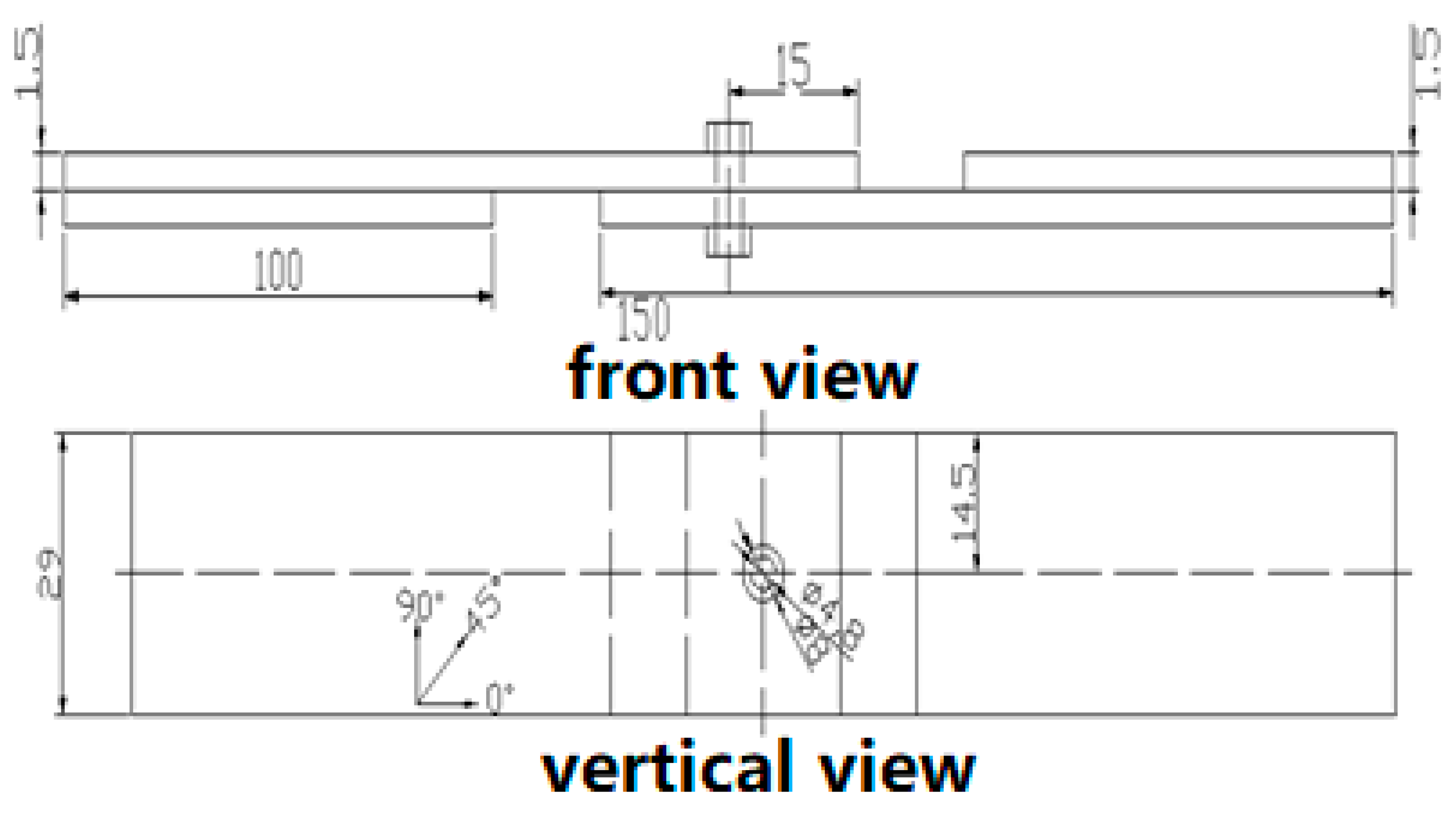
Figure 1 shows the geometry of the bolted joint.
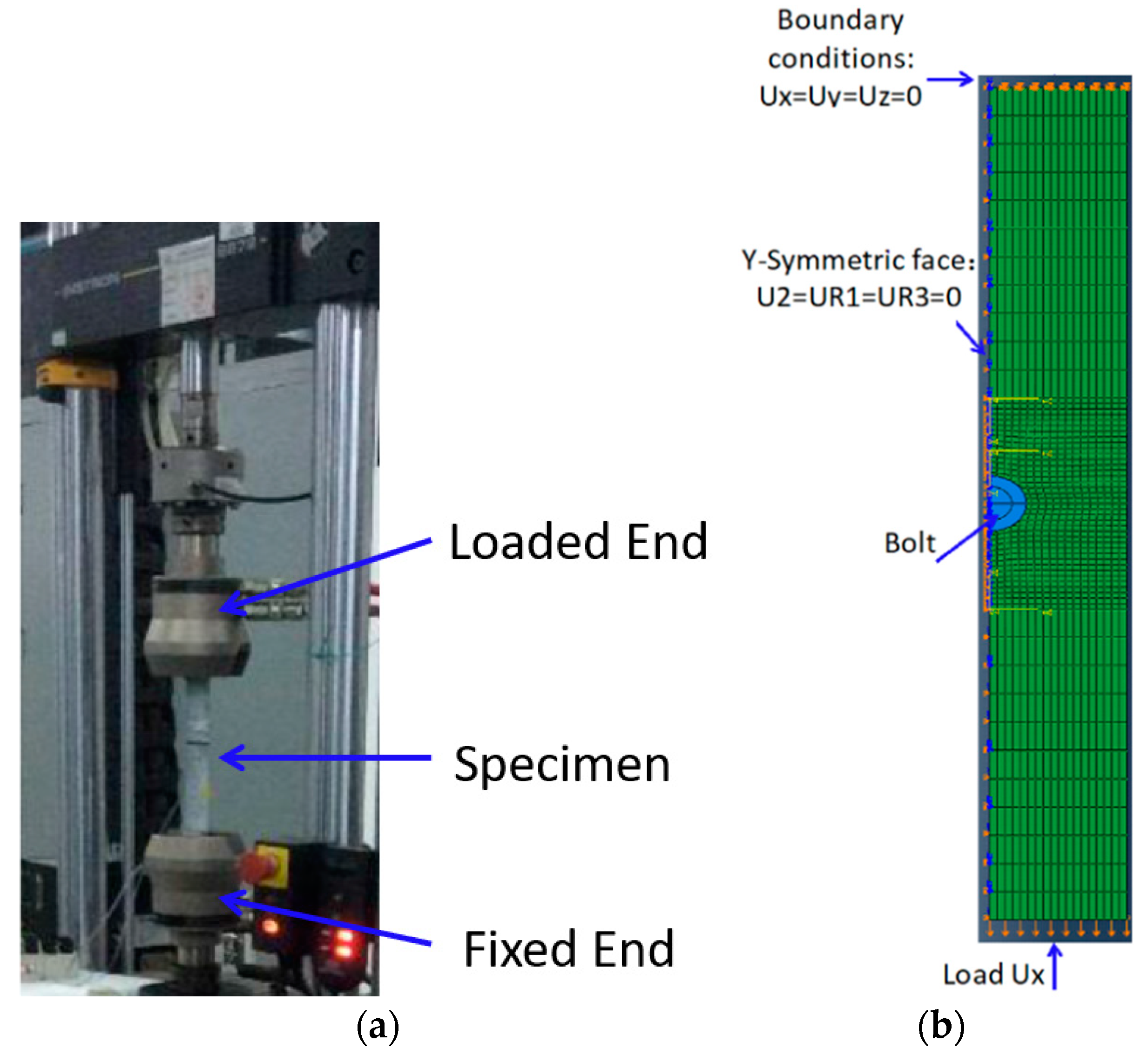
Figure 2a,b show the experiment and diagrammatic sketch of numerical model, respectively.
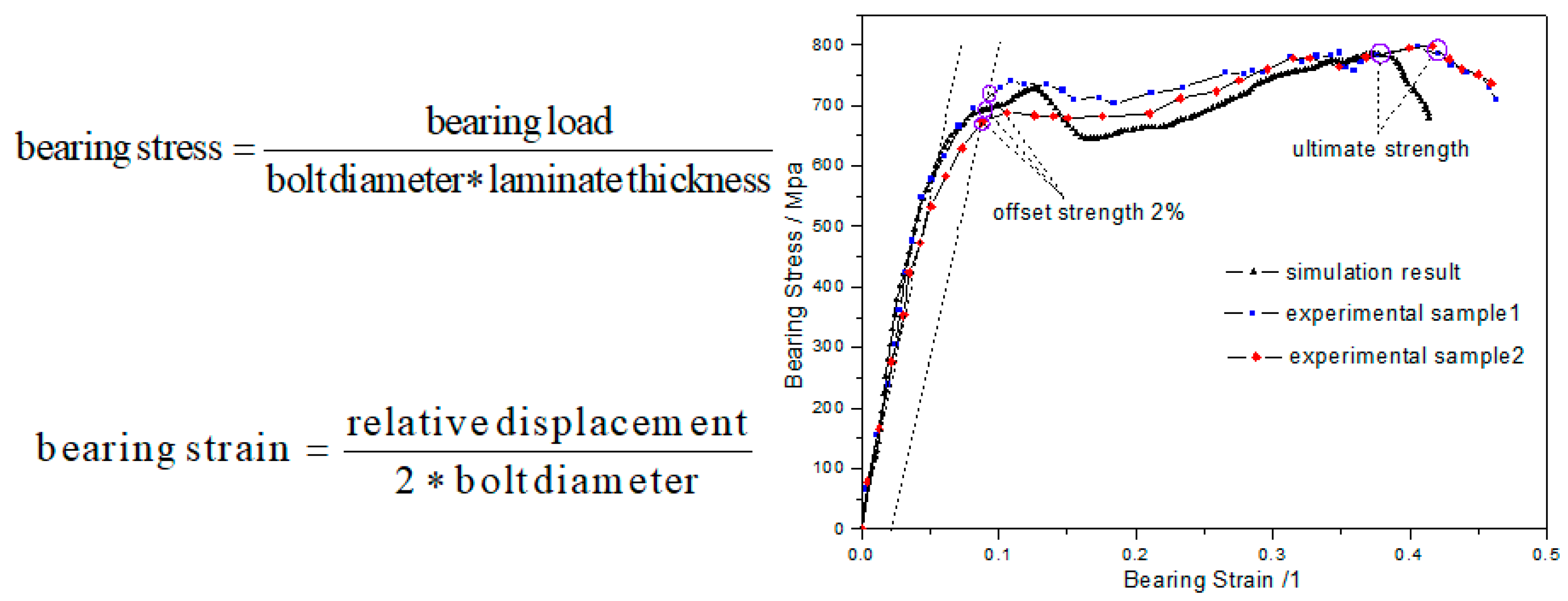
Figure 3 shows the comparison of experiment and simulation. The two bearing stress curves show an excellent agreement. The results indicate that the numerical model has sufficient accuracy to reflect the deformation process of bolted joint.
4. Dynamic Model
The composite material has strain rate effect under high speed loading. It needs to consider the effect of strain rate effect on the strength parameter. Therefore, assume the strength S of the T800/QY8911 consists of two parts:
where α is the initial strength at the reference strain rate, β and γ are modification items of strain rate effect.
Through testing on Hopkinson Bar, we obtain the parameters of the strain rate effect, as shown in
Table 2. The strengths and modulus of the other directions are not strain-rate-dependent.
Then dynamic compression simulation is conducted.
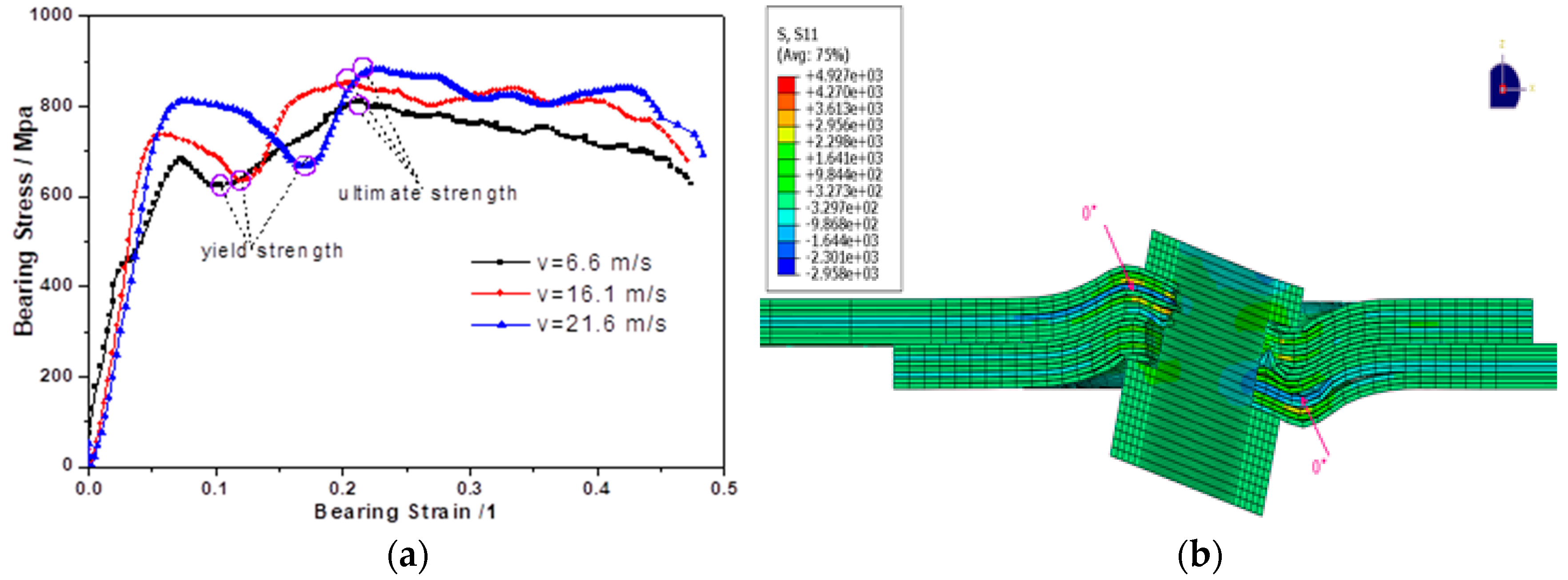
Figure 4a shows the simulation results and indicate that the strain rate effect has obvious influence on dynamic compression yield strength and ultimate strength of composite single-bolted joint. Strain rate hardening increases the carrying capacity of bolted joint.
Figure 4b shows the deformation mechanism. The main damages are 0⁰ sublayer buckling and fiber breakage caused by extrusion.
5. Conclusions
This study investigates the dynamic strength of the composite joint. Using finite element technique, we present a three dimensional progressive damage model based on the theory of continuous damage mechanics for composite laminates to be used for composite single-bolted joint is presented. Under dynamic compression loading, the yield strength and ultimate strength increase with the increasing load rate due to strain rate effect. The significant damages are fiber breakage and buckling in 0⁰ sublayer.


