1. Introduction
The use of laminate composite materials, in the industrial field today knows a significant growth in recent years. This increase is explained by the fact that manufacturers, particularly the aeronautical industry, which was a pioneer in this field; is interested in lightening their structure in order to meet the environmental challenges of our time.
Indeed, the laminates composites are often subjected to impacts and multi-impacts during their use. The example of impact of the hailstone in aeronautic field. It would be necessary to know the behavior with the multi-impacts tests in order to be able to choose the stratification adapted for the designing of the composite parts.
Some studies have been done on low velocity multi-impact tests in the literature like. Amaro et al. [
1], they were carried out some studies on the influence of multi-impact on graphite/epoxy at different energies, the impact responses showed that when the energy of impact is high the maximum force and displacement increase also. Further in the studies, Amaro et al. [
2] also evaluated the effect of the temperature of the multi-impact tests. For greater energy, they didn’t notice any influence of temperature but for low energy, the breaking plate composite appeared tardily for the low temperature. Morais et al. [
3] noticed that the stratifications of the material had a significant influence on the performance of the multi-impact tests of the composite material. They found that non-symmetric cross-ply composites perform better than unidirectional composites. Coelho et al. [
4] had submitted both configurations (single and double path) to multi-impacts. They concluded that the double path supports higher maximum loads, lower displacements compared to the single path.
The objective of this paper is to see a global approach of the propagation of the damage during the tests multi-impacts and compare the stratifications to the tolerance of multi-impacts. We find a parameter of designing of composite structure.
2. Materials and Methods
2.1. Materials-Process
The material used in this study is unidirectional pre-impregnated carbon epoxy material named CTE1 15 fabricated by STRUCTIL® in France. The carbon fiber in this material is TR50S HR and its high tensile strength is approximately 4900 MPa. The resin which was used is the epoxy R367-2. Resin represents 38% of the material whereas the other 62% is fiber.
The pieces of material are draped in sequence according to the desired stacking sequence into 400 × 400 mm
2 sheets. Finally, the sheets are pressed in hot press. The used manufacturing cycle is shown in (
Figure 1).
2.2. Stratifications
The studies were focused on three different stacking sequences composed with 24 plies and 3.6 ± 0.01 mm of thickness: QIQH45, QIQH60 and AERO (see
Table 1). The name AERO, results from the aeronautical field in which it is used. QIQH45, QIQH60 result respectively from the quasi-homogeneous and quasi-isotropic denomination due to their 45° and 60° fiber orientation.
2.3. Multi-Impacts Procedure
The impact test machine used, is an Instron Dynatup 9350 HV drop weight test machine. A hemispherical impactor of 12.7 mm diameter and 5.99 kg has been used during test. The specimens are clamped on all four edges and a circular area of 76 mm diameter is left for the impact. The impact test machine is equipped with anti-rebound system to prevent the occurrence of multi-impact at once and thus enabling the data collection of one impact at one time. The tests have been done on specimen 100 × 100 × 3.6 mm3.
3. Results and Discussions
This section present the results of multiple impacts tests. The tests are conducted until perforation and a parameter
D is established following the shape of experimental curves. A specific parameter
D have a following expression:
where
P0 and
Pα are coefficients of the slope of the force-displacement curves of 1 J impact test (elastic) and of the current impact after
impacts, respectively. For all stratifications, the tests are stopped before the parameter
D is equal to 0.9.
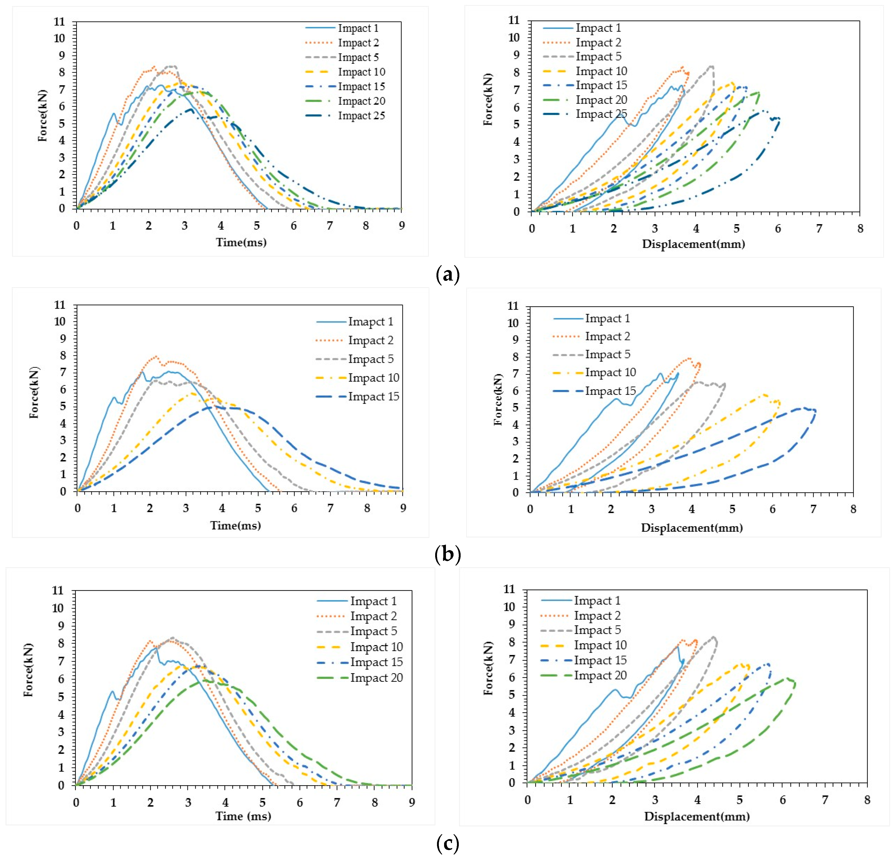
Figure 2 presents the force-time and force-displacement curves of each stratification studied.
In general, the curves of the multi-impact tests have the same trend. The tests carried out at 15 J, show that there is an evolution of the curves after each impact. After the first impact, the damage is initiated; thus from the second impact to the end impact, the contact time increases and the maximum force decreases. For QIQH45, we observe a decrease in the maximum force of approximately 30% between 2nd impact and 25th impact can be noted in (
Figure 2a). It can be noted also that, between 2nd impact and 20th impact, the curve are as bell type shape. Beyond that, we can notice a plateau of force more or less pronounced where the maximal force is constant between interval contact time [3.2–4.2] ms. This plateau type shape can be explained as slow propagation of damage.
The same analyses (same trend) can be done on the other two stratifications. But we notice for QIQH60 that the maximum force decreases 46% between 2nd and 15th impact (
Figure 2b). In case of AERO (
Figure 2c) the maximum force decrease by 25% from 2nd to 20th impact.
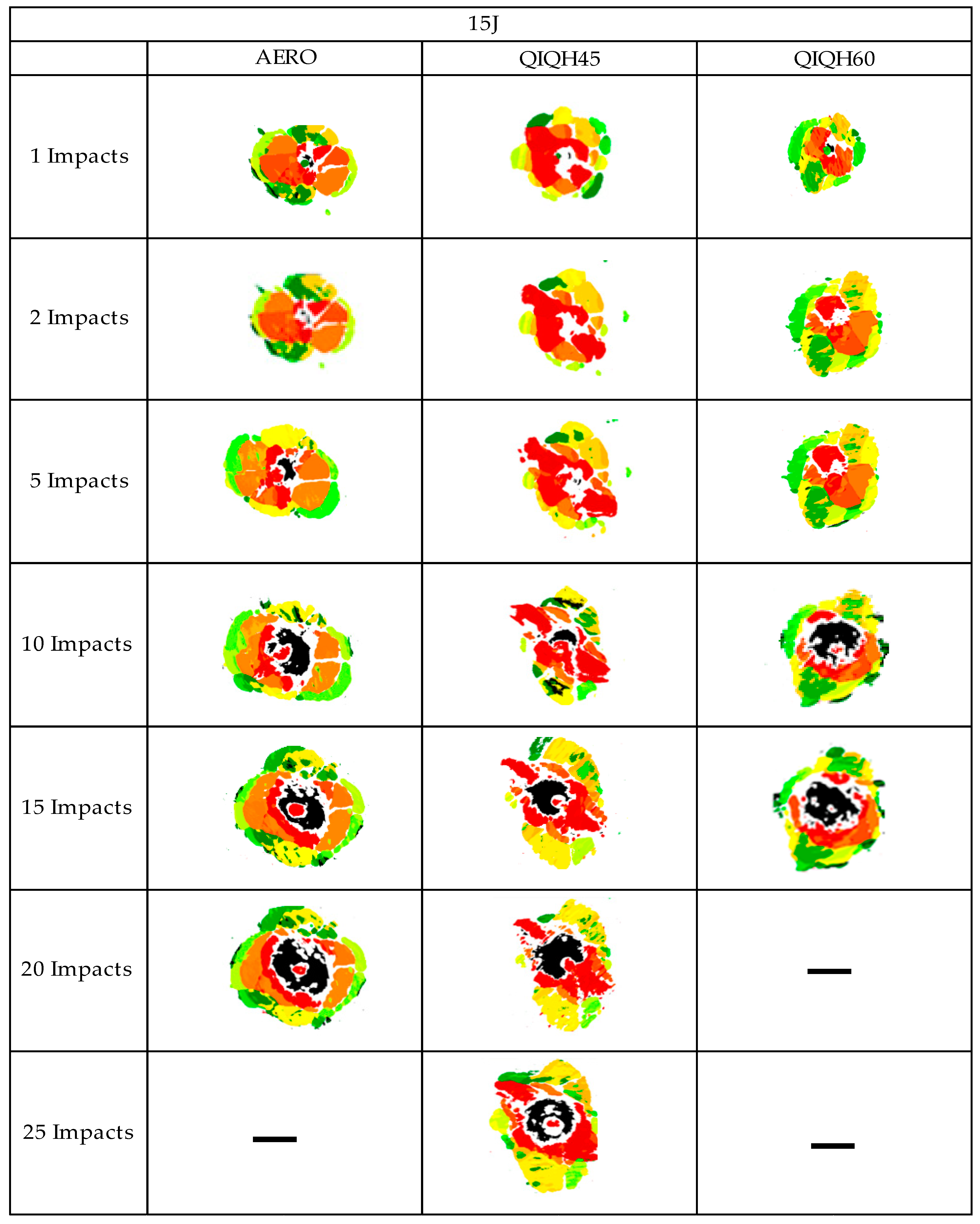
In order to evaluate the damage qualitatively and quantitatively, the figures present respectively the C-Scan images for the three stratifications (
Figure 3).
The studies C-scan show homogeneous damage for AERO. The shape of the damage has the form of a spiral from the impact surface to the interior surface of the laminate composite.
For the C-scan results obtained for QIQH45 and QIQH60, there are preferred orientations for QIQH45° and QIQH60° with a significant expansion of damage in the depth of the laminate. There is also a respective influence of the plies at 45° and 60° in the delamination orientation in the depth of the laminates, especially at the surface. QIQH sequences tend to extend substantially from the point of impact as depth increases. As expected, there is an increase in damage with number of impacts and in some cases, the appearance of new damage to interfaces undamaged during the previous impacts.
We have also noted that the area directly under the impactor becomes increasingly difficult to analyze with an increasing number of impacts. During the initial impacts, the damage is mainly due to the presence of a compression zone and if the number of impacts becomes significant, there is the presence of chaotic damage zone important improperly evaluated in thickness (
Figure 3).
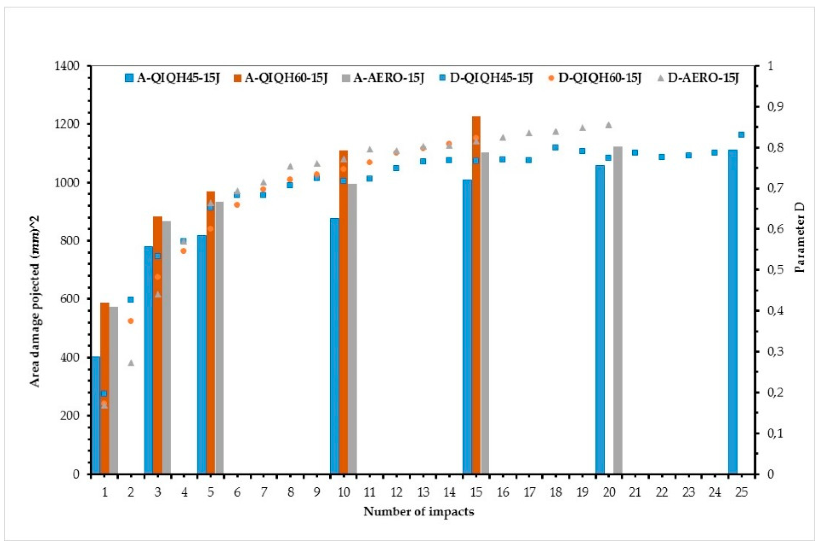
Figure 4 presents the evolution of parameter D in parallel with the evolution of the projected damaged area versus number of impacts. We notice that the projected damaged area increase when the number of impact increase.
The curves of parameter D and the projected damaged area show that the QIQH45 sequence has the best tolerance to multi-impact tests followed by AERO and QIQH60 There is correlation between parameter D and projected damage area obtained by C-scan.
4. Conclusions
In this work, the multi-impact tests were investigated on three stratifications AERO, QIQH45 and QIQH60 at different energies. From the results of test multi-impact obtained, a parameters D are introduced following the multi-impacts test. No destructive controls are used to evaluate the damage on material composite after impact.
Parameter D versus number of impacts, QIQH45 presents the best tolerance of multi-impacts followed by AERO and QIQH60. The multi-impacts test show the influence of stratification on the material composite.
The C-scan figures obtained, show that the area damage increase with number of impacts and there are some preferred orientation of fibers particularly 45° and 60° for the stratifications QIQH45 and QIQH60 respectively.
The result show the correlation between projected area damage obtained by C-scan and the parameters D versus number of impacts.


