Abstract
One of the major challenges for the realization of ultra-light weight and intelligent materials with advanced sensing/actuation capabilities, is related to, among other things, the integration in the material of non-invasive but indeed highly performing sensors and actuators. The reduction in scale, weight, and flexibility of the sensing devices represents a critical aspect to reach this goal. These unique properties are here reached by using flexible piezoelectric polymer (Polyvinylidene fluoride, PVDF) nanofibers as sensing elements. The nanofibers, that in this case study are randomly distributed, form an ultra-thin nanostructured porous mat that was deposited through a far field electrospinning approach. The process was optimized to obtain a dominant β phase in the polymer to enhance the piezoelectric response. The electrospun fibers were characterized at different scales: at the molecular level to understand the β phase content (FTIR spectroscopy), as well as at the macroscopic level to investigate the resulting ferroelectric and electromechanical response The results presented in this paper show the great capability of the nanostructured porous mat to work as ultra-light weight dynamic sensing system. Its scalable size and intrinsic properties make it an ideal solution for the development of advanced intelligent materials that can work at different length-scales.
1. Introduction
Intelligent materials can be interpreted as such materials that store an intrinsic “intelligence” or, in other words, that are capable to perform multiple or single unique functions. These functions can be a consequence of the crystal or molecular structure of the material, or they can somehow be inserted in a passive material by integrating it with intelligent fillers. It is quite obvious that, in the latter case, the fillers should be as much as possible non-invasive in order to avoid a deterioration of the properties of the hosting material. For the specific case of a sensing or actuating intelligence (e.g., strain), the smart filler should be a sensor or an actuator. The most common commercially available strain sensors or actuators (e.g., strain gauges, piezoelectric ceramics/polymers, and optical fibers) are relatively large in size, require time-consuming mounting approaches as well as several connecting wires. For these reasons, these devices can be applied in a small number over large structural surfaces. Some devices, like strain gages and optical fibers, can only be used as local sensing devices, while other devices, like piezoelectric-based, have the beauty of being characterized by a dual sensing/actuation capability. Piezoelectric ceramics are brittle in their nature and can provide a limited strain range, while piezoelectric polymers (as PVDF) are extremely flexible and can work under large strain conditions. Advances in nano- and micro-technologies are definitely opening interesting opportunities in this contest but several challenges still need to be addressed in order to achieve the above mentioned functions. Smaller-in-scale device in fact have a lower impact when embedded into a hosting material, but they still suffer of the above mentioned assembling and wiring issues. For this reason we believe that a promising approach should rely on the realization of intelligent nanofillers that can be uniformly spread within the composite without impacting its integrity. These fillers should be light-weight, flexible, small in scale, sensitive to specific parameters and capable to provide specific actions.
Polyvinylidene fluoride (PVDF) is an interesting material because of its piezoelectric properties, excellent mechanical strength, flexibility, easy adaptability and good workability. These properties make it a perfect candidate for the above mentioned scope in the case in which pressure strain [1,2] and vibration [3] should be monitored and/or a mechanical actuation should be induced in the material. PVDF is a semi-crystalline polymer which, depending on the processing conditions, can have four different polymorphisms: phase α, β, γ and δ. These four polymorphisms imply three distinct chain configurations, composed of T (trans) and G (gauche) conformations [4].
The β phase has the highest iron and piezoelectric properties. This phase can be generated by mechanical stretching and subjecting the polymer to a high electric field. In fact, the molecular orientation can be reached by the elongation process along the axis of the main chain that allows the alignment of the dipoles [5].
This paper focuses on the realization and characterization of a smart filler that can sense strain and vibration. The filler is formed by PVDF nanofibers that are randomly aggregated forming an ultra-light weight porous mat. The nanofibers are produced through a far field electrospinning approach that allows for an in-situ and direct material polarization [6,7,8,9] for enhanced piezoelectric properties.
2. Manufacturing Process
PVDF powder, with a molecular weight of 534 g/mol, acetone and N,N-dimethylacetamide (DMAc) (Sigma-Aldrich, St. Louis, MO, USA) are used without further purification. PVDF powder is dissolved in N-dimethylacetamide (DMAc), then Acetone is added and the overall solution is mixed for 1 h at high temperature using a hot plate. The solution mix of DMAc and acetone plays a very important role in the viscosity of the final mixture. The acetone lead to an overall decrease in the viscosity of the mixture introducing a high volatility to the polymer solution. The containers were then sealed with aluminum foil and left to stand for a few minutes.
Randomly distributed electrospun fibers are obtained with a far field electrospinning setup (Figure 1a). The nanofibers morphology, in terms of fibers diameter and its uniformity as well as the presence or absence of defects, depends on specific process parameters (voltage, needle-collector distance and flow rate) (Figure 1b).
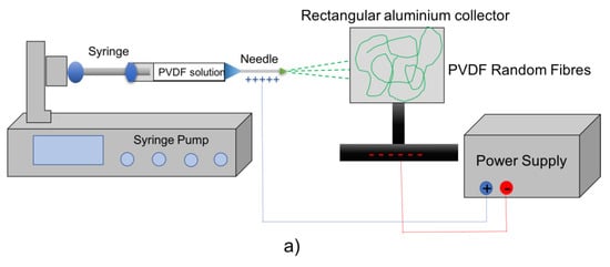
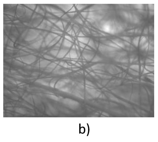
Figure 1.
(a) far field electrospinning setup; (b) Microscope image of the PVDF porous mat formed by random fibers.
The fibers are deposited on a rectangular aluminum collector by applying an electric field greater than 10 KV, a needle-collector distance of 20 cm and a flow rate equal to 0.08 mL/h.
3. Results and Discussion
The morphology of the electrospun nanofibers can be viewed through the optical microscope image in Figure 1b. The fibers, with an average diameter of 3–5 µm, are randomly and uniformly distributed on the collector. The functionality of the fibers is strictly related to the crystalline phases of the material. For this reason an infrared spectroscopy (FR-IR) analysis, that consists in measuring the absorption of IR radiation by the fibers placed on the beam path, is performed. The resulting infrared spectrum provides the absorption bands, that are reported relative to the various crystalline phases of the fibers, as a function of the wave number (Figure 2). The FT-IR spectrophotometer (Bruker interferometer model Vector 22), in this case is operated in the 400–4500 cm−1 wave number range.
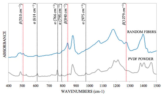
Figure 2.
Comparison of the FT-IR spectra of the powder and of the random fibers to observe the transformation of the α phase in the β phase.
These characterization tests are useful to highlight the transformation of the non-polar phase (α-phase) in the polar phase (β-phase) during electrospinning. To this end, the graph in Figure 2 compares the spectrum of the PVDF powder and of the fibers. The powder shows dominant peaks that correspond to the non-polar phase (α-phase) and this indicates that the powder is not piezoelectric. On the contrary, the spectrum of the random fibers shows negligible non-polar peaks and dominant polar phase (β-phase) peaks, which is the most important phase for piezoelectric and pyroelectric properties.
The formation of the β phase that is found in the electrospinned fibers is mostly due to the high voltage applied to the electrospun solution and to the simultaneous uniaxial mechanical stretching that occurs in the polymer jet during electrospinning. In addition, the low crystallization temperature resulting from the low environment temperature during electrospinning and the rapid evaporation of the solvent could also play a role in the β phase predominance in the PVDF fibers.
At the macroscopic level, the ferroelectric properties of PVDF nanofibers are investigated with the aid of a Ferroelectric Tester (Precision LC, Radiant Technologies, Inc., Albuquerque, NM, USA) to generate a correct hysteresis cycle P (polarization) vs V (Voltage) (Figure 3).
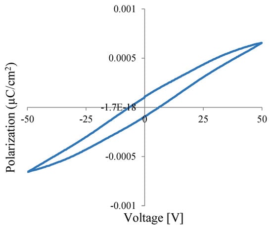
Figure 3.
Hysteresis loop of PVDF nanofibers.
The graph shows an hysteretic behavior, a remanent polarization of 0.0001 µC/cm2 and a coercive voltage of 6.9 V, which highlights a piezoelectric response of the nanofibers. In the test, the complete saturation in the hysteresis cycle has not been reached because the instrument does not allow to apply higher voltages, the maximum applied voltage in this case is of 50 V. An increase in voltage in fact increases the size of the hysteresis loop.
The dielectric constant of the piezoelectric fibers is determined by performing capacitance measurements (Semiconductor Parameter Analyzer, Agilent, Santa Clara, CA, USA) of the piezoelectric nanofibers. The sample was prepared by placing a layer of fibers between two aluminum electrodes in a sandwich configuration. The measured capacitance value and the dielectric constants, that were carried out by applying an AC signal of 500 mV and Dc signal of 500 mV, are shown Table 1. The capacitance was measured in a frequency range of 1 KHz to 10 MHz. The dielectric constant was calculated at 10 KHz since the accuracy of the test equipment is optimal at this frequency.

Table 1.
Capacitance test results.
The electromechanicl properties of the electrospun nanofibers are investigated by sandwiching PVDF fiber mat, with a thickness of about 200 µm, between two copper electrodes, on which electrical connection are soldered (Figure 4 left). The sample was then mounted on a fiberglass cantilever. Free oscillations are induced in the cantilever by imposing, and then instantly releasing, a constant vertical displacement at its free end. These oscillations are monitored with the help of a high precision laser (Laser Vibrometer, Polytec) which allow to acquire the time history in terms of velocity. The Fourier Transform of the detected signal allows to calculate the first vibration mode of the cantilever. Simultaneously the fiber mat is connected to a digital oscilloscope (Digital Storage Oscilloscope 2556, BK Precision) to record the output signal in terms of voltage as a function of time. This signal is again transformed to detect the first vibration mode of the cantilever (Figure 4 right).
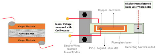
Figure 4.
(left side) schematic representation of the PVDF fiber mat sensor in the sandwich configuration; (right side) Schematic representation of the sensing test setup.
Figure 5a shows that the fiber mat and the laser time histories are very well overlapped in terms of phase and frequency. M the frequencies of the first vibration mode of vibration are very close to each other (93.99 Hz and 93.09 Hz for the fiber mat and laser respectively). The excellent matching of these data highlights that the nanofiber mat can be safely used for advanced sensing applications and as smart filler for the development of novel intelligent materials.
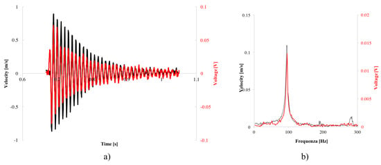
Figure 5.
(a) Comparison of the laser response and of the electrospun sensor; (b) Fourier Transform with random fibers.
4. Conclusions
Polyvinylidene fluoride (PVDF) nanofibers were prepared by electrospinning and characterized with several techniques in multiple scales. The manufacturing process was optimized by varying key process parameters. The obtained mats of randomly distributed fibers showed excellent piezoelectric properties as well as a great uniformity in terms of fiber diameter/surface. The highlighted properties, the low cost manufacturing process, the ease of workability, the high chemical resistance and the excellent piezoelectric properties, make this mat very useful for creating ultra-light and flexible strain/dynamic sensors as well as for making advanced fillers for next generation of composite materials.
Author Contributions
G.L. conceived and designed the experiments; F.F. and K.C.C. fabricated the samples and performed the experiments; I.G. performed the FTIR experiments and interpreted the data with F.F.; G.L. and F.F. wrote the paper.
Acknowledgments
The research leading to this work was supported by the European Research Council under the European Union’s Seventh Framework Program (FP/2007-2013)/ERC Grant Agreement no. 308261.
References
- Shirinov, A.; Schomburg, W. Pressure sensor from a PVDF film. Sens. Actuators Phys. 2008, 142, 48–55. [Google Scholar] [CrossRef]
- Sirohi, J.; Chopra, I. Fundamental Understanding of Piezoelectric Strain Sensors. J. Intell. Mater. Syst. Struct. 2000, 11. [Google Scholar] [CrossRef]
- Lei, T.; Xu, L.; Zhan, Z.; Du, J.; Jiang, Y.; Zheng, G.; Wang, L.; Sun, D. Direct Fabrication of Polymer Nanofiber Membrane for Piezoelectric Vibration Sensor. In Proceedings of the 2011 IEEE SENSORs, Limerick, Ireland, 28–31 October 2011. [Google Scholar]
- Mokhtari, F.; Latifi, M.; Shamshirsaz, M. Electrospinning/electrospray of polyvinylidene fluoride (PVDF): Piezoelectric nanofibers. J. Text. Inst. 2015, 107, 1037–1055. [Google Scholar] [CrossRef]
- Lei, T.; Yu, L.; Zheng, G.; Wang, L.; Wu, D.; Sun, D. Electrospinning-induced preferred dipole orientation in PVDF. 2015, 50, 4342–4347. [Google Scholar] [CrossRef]
- Luo, G.; Teh, K.S.; Liu, Y.; Zang, X.; Wen, Z.; Lin, L. Direct-write, self-aligned electrospinning on paper for controllable fabrication on three-dimensional structures. ACS Appl. Mater. Interfaces 2015, 7, 27765–27770. [Google Scholar] [CrossRef] [PubMed]
- Choi, S.W.; Kim, J.R.; Ahn, Y.R.; Jo, S.M.; Cairns, E.J. Characterization of electrospun PVDF fiber-based polymer electrolytes. Chem. Mater. 2007, 19, 104–115. [Google Scholar] [CrossRef]
- Zheng, J.; He, A.; Li, J.; Han, C.C. Polymorphism Control of Poly(vinylidene fluoride) through Electrospinning. Macromol. Rapid. Commun. 2007, 28, 2159–2162. [Google Scholar] [CrossRef]
- Liu, Z.H.; Pan, C.T.; Lin, L.W.; Huang, J.C.; Ou, Z.Y. Direct-write PVDF nonwoven fiber fabric energy harvesters via the hollow cylindrical near-field electrospinning process. Smart Mater. Struct. 2013, 23. [Google Scholar] [CrossRef]
Publisher’s Note: MDPI stays neutral with regard to jurisdictional claims in published maps and institutional affiliations. |
© 2018 by the authors. Licensee MDPI, Basel, Switzerland. This article is an open access article distributed under the terms and conditions of the Creative Commons Attribution (CC BY) license (https://creativecommons.org/licenses/by/4.0/).