Proceeding Paper

Insights into Acoustically Induced PiezoLuminescence: The Visualization of Ultrasonic Beam Patterns †

1
Department of Solid State Sciences, LumiLab, Ghent University, 9000 Ghent, Belgium
2
Center for Nano- and Biophotonics, Ghent University, B-9052 Ghent, Belgium
3
Department of Materials, Textiles and Chemical Engineering (MaTCh), Mechanics of Materials and Structures (MMS), Ghent University, B-9052 Ghent, Belgium
4
Physics of Fluids Group, Technical Medical (TechMed) Research Institute and MESA+ Institute for Nanotechnology, University of Twente, P.O. Box 217, 7500 AE Enschede, The Netherlands
*
Author to whom correspondence should be addressed.
Presented at the 18th International Conference on Experimental Mechanics (ICEM18), Brussels, Belgium, 1–5 July 2018.
Proceedings 2018, 2(8), 491; https://doi.org/10.3390/ICEM18-05411
Published: 29 June 2018
(This article belongs to the Proceedings of The 18th International Conference on Experimental Mechanics)

Abstract

:
Ultrasonic transducers are used in many fields of application, including medical imaging/treatment, non-destructive testing and material characterization. To assure the quality of the ultrasonic investigation transducers require regular checks for possible deterioration and accurate calibration. Current methods rely on point-by-point scanning of the ultrasound field with a needle hydrophone, which is expensive and time consuming. Recently, we have developed a new concept, in which a fast full-field visualization of the radiation field is achieved through Acoustically induced PiezoLuminescence (APL). Here, we report on an improved ultrasonic beam visualization and provide further insights into the mechanism underlying APL and mechanoluminescence.

1. Introduction

Ultrasonic waves are compressional waves with a frequency over 20 kHz. Many non-destructive inspection techniques study the scattering or transmission of ultrasound as it propagates through the object of interest. With that aim, ultrasonic waves are generated (and collected) by a piezoelectric transducer. Advanced applications of ultrasound technology, including non-destructive testing and biomedical imaging require a 2D or even 3D reconstruction of the target. Therefore a full characterization of the emitted ultrasound field is of utmost importance to enable adequate results. Furthermore, the presence of small deviations in the piezoelectric element inside the transducer housing can give rise to a non-symmetric and poorly focused ultrasonic beam, thus leading to possibly false interpretation. As a consequence, transducers require regular checks during their operational life (so called quality assurance (QA) tests) [1,2].
Current calibration technologies solely rely on scanning techniques, typically using costly needle hydrophones, which present two major limitations. First, these methods require mechanical movement between every scanned point, making them vastly time consuming. Secondly, the size to sensitivity ratio of needle hydrophones impedes their use for high-frequency fields which are being applied more often in ultrasound technology.
Mechanoluminescence (ML) is a specific type of luminescence where a material emits visible light upon the application of a mechanical load. Just like most luminescent compounds (also called phosphors), ML materials consist of a semiconducting or dielectric host crystal doped with a small fraction of optically active elements (e.g., transition metals or lanthanides). When such a material is exposed to an external energy source (e.g., UV light), charge carriers can get sufficient energy for transitions between the available energy levels. The dopants provide such energy levels inside the band gap of the host crystal, creating new possibilities for radiative transitions of the charge carriers, with subsequent emission of visible light, typically with a lower energy than that of the original source. Some luminescent materials (called persistent phosphors) contain defects in the host crystal (e.g., other substitutional elements, vacancies …) which also create energy levels in the band gap of the phosphor. There, charge carriers can remain trapped for extended periods of time (seconds to hours) before being promoted through absorption of external energy (e.g., thermal energy at room temperature). This eventually leads to light emission from the emitting dopant center, resulting in the well-known afterglow or “glow in the dark” phenomenon [3,4].
According to the piezoelectrically induced electron detrapping model (PIED) [5], a persistent phosphor can show ML when the host crystal is built up from non-centrosymmetric unit cells, effectively making host crystal a piezoelectric material. In these crystals, external mechanical stimulation induces the generation of a local, internal electric field with sufficient energy to detrap the charge carriers from the defect levels and induce the emission of visible light. The physical mechanisms underlying this ML phenomenon are not entirely understood, and various explanations and models coexist. Further investigation is therefore required. For a comprehensive overview of existing models, the interested reader is referred to [6].
By combining ultrasound and ML, we have previously reported a new concept for ultrasound visualization and investigation of Acoustically induced PiezoLuminescence (APL) [7]. After Zhan et al. presented the proof of concept in 2011 [8], this was the first time ML was used to visualize cross sections of an ultrasonic field at different distances to the transducer. Here, we report on our experimental investigation of APL and its dependency on various ultrasonic parameters.

2. Material and Methods

2.1. Sample Preparation

The investigated APL compound was BaSi2O2N2 in which 2 wt % of the Ba2+ ions were replaced by Eu2+ (abbreviated as BaSiON), which was prepared through a solid state reaction in what is called the “shake and bake” method. In this procedure, stoichiometric amounts of starting chemicals BaCO3, Si3N4 and EuF3 were thoroughly ground and mixed. They were then placed in an alumina crucible, heated to 1425 °C and kept at that temperature for 4 hours in an atmosphere of forming has (90% N2 + 10% H2). This allowed the reduction of the Eu3+ ions of the starting materials into Eu2+, which could then replace Ba2+ atoms. The resulting crystal was crushed to obtain micropowders with a size distribution of 1–50 µm.
For APL visualization, these powders were embedded into a transparent polymer matrix by mixing them with a 3:1 solution of toluene and methylethylketone (MEK) which contained 20 wt % of Kraton FG1901X polymer. This mixture was dropcasted on a Plexiglas substrate after which the solvents were allowed to evaporate. The loading ratio of phosphor material to polymer was chosen to be 1:5 in order to obtain a semi-transparent, yet sufficiently luminescent sample.
For investigating the APL dependency on various ultrasonic parameters, the powder was fixed between two sheets of transparent polyethylene film to create semi-transparent sheet-like samples.

2.2. Experimental Setup

The first setup for ultrasound visualization used in [7] (see Figure 1) had a few drawbacks as it was used for a proof of concept only. New semi-transparent samples were introduced in order to allow APL detection from the opposite side of ultrasound impingement.
The study of the APL mechanism and the influence of ultrasonic parameters was performed on a setup built at the Physics of Fluids group (PoF) at the UTwente. In order to avoid standing waves in the sample and allow for a quantitative measurement, a setup was designed where BaSiON sheets (with a thickness below the typical ultrasonic wavelengths) were inserted in a water tank, allowing them to be irradiated from the bottom with a focused ultrasound transducer (Olympus panametrics). Before each measurement, the sample was optically charged with a UV blacklight lamp controlled by a relay for accurate timing.

3. Results

3.1. Improved Ultrasound Visualization

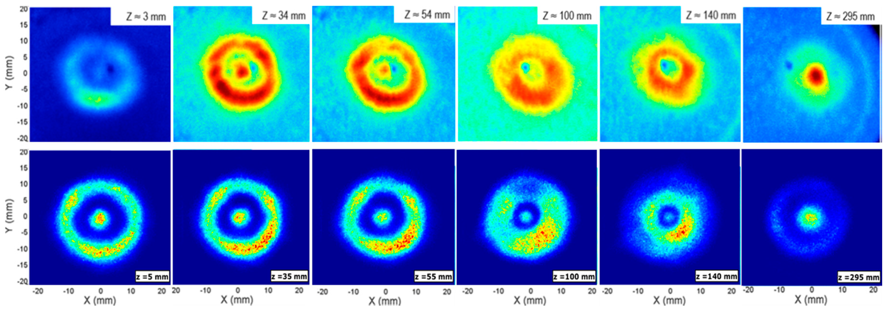
Using the improved setup described in the experimental section, a new APL visualization was performed of the same transducer as in [7] (Gymna 200 apparatus, operating at 3.3 MHz and 9.5 W acoustic power), this time measuring a cross section every 5 mm along the beam path rather than at a few positions. The images were combined into a movie, which can be viewed online (a link is included in the supplementary materials section). A selection of cross sectional APL images is compared with those obtained with the original setup in Figure 2.
From these pictures it is evident that the use of a sub-wavelength-thick sample results in a major improvement of the spatial resolution (for example see z = 295 mm or z = 100 mm) as interferences within the sample, wave attenuation and scattering, both of light and ultrasound, are minimized. It is also clear that the patterns are not perfectly symmetric, but have regions of higher intensity along the outer ring (especially visible in the near field of the transducer, at z < 200 mm). Rotating the sample had no visible effect on the observed pattern the patterns, thereby confirming that the asymmetry results from irregularities in the piezoelectric element or matching layer of the transducer.

3.2. Investigation of the APL Mechanism

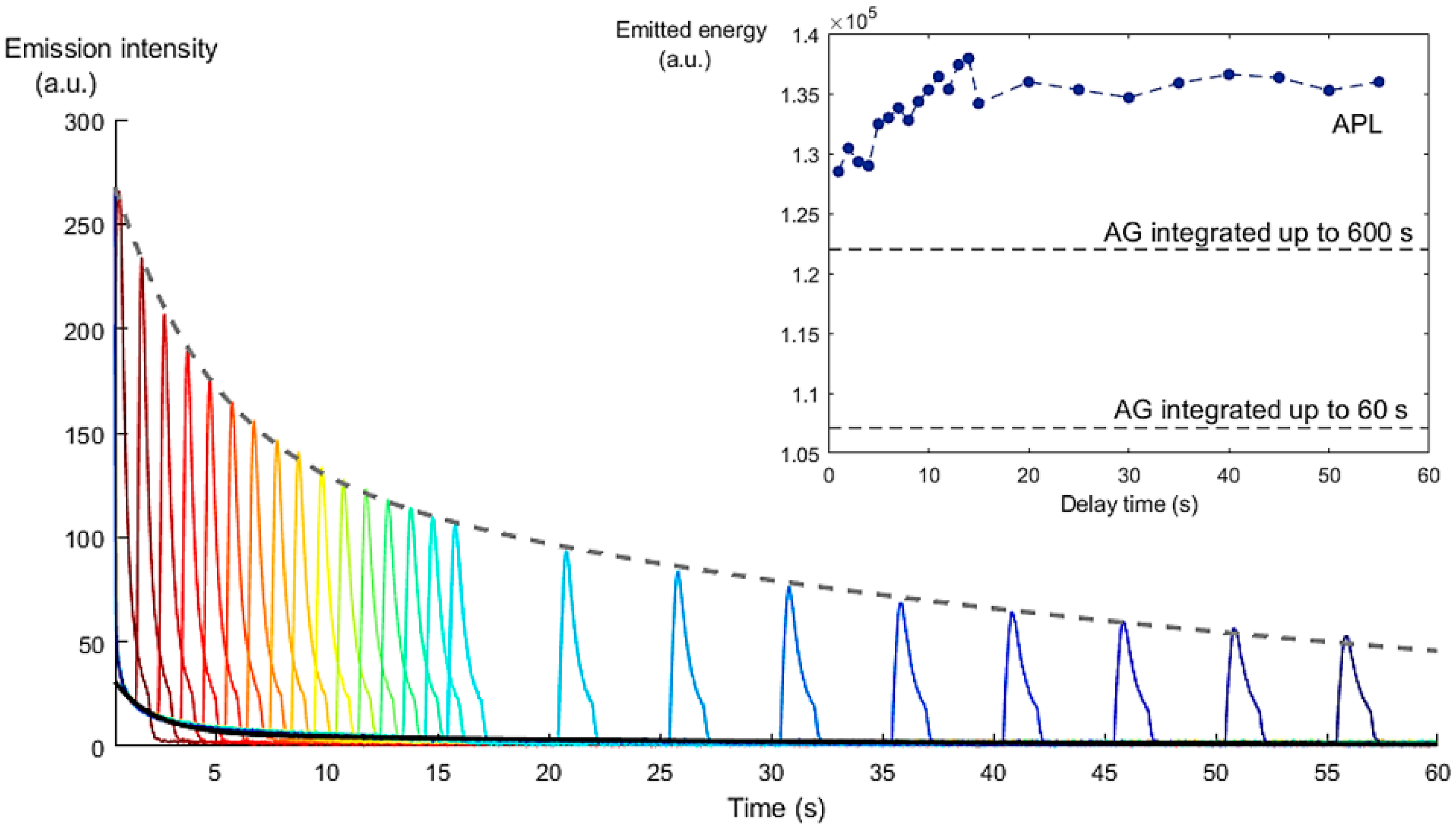
Figure 3 shows a combination of 24 APL experiments, each performed at a specific time delay after the end of optical excitation (t = 0). After this time delay, the sample was irradiated by a 1.5 second-long ultrasound burst at 4 MHz and 2.2 MPa acoustic pressure. The afterglow of the BaSiON sample (without mechanical stimulation) is depicted by the solid black line. For each measurement, the typical peak in emission is visible when the ultrasonic transducer is switched on. Then the APL emission reaches a peak saturation value and starts declining, until the ultrasonic stimulation is switched off and the intensity drops below the afterglow. The grey dotted line depicts the result of a double-exponential fit to the APL peak values. The inset shows the total area under the curve for each time delay, with respect to the afterglow level (as integrated for 60 s for this experiment, as well as for 600 s, from a reference measurement). This kind of integrated area under a curve can be related to the total emitted energy during one experiment.
It is clear that the APL peak intensity decreases with the delay time, in a similar fashion to the afterglow. Both can be described by a double-exponential fit of the form
I(t) = a × exp(−b × t) + c × exp(−d × t),
where the parameter b determines the fast part of the decay, and d the slow part (the tail). When we compare these two parameters for fits to the APL peak intensities and to the afterglow, we find that the former drop at approximately half the rate of the latter: bAPL = (0.2348 ± 0.0269) s−1 versus bAG = (0.5450 ± 0.0035) s−1 and dAPL = (0.0186 ± 0.0017) s−1 versus dAG = (0.0313 ± 0.0002) s−1. This indicates that APL emission has access to the same pool of trapped charges as the afterglow, with a similar trap depth distribution, but that it depletes this energy pool at a slower rate. This result is confirmed in the inset, where the total emitted light during an APL experiment is higher than that of the reference afterglow (when integrated up to 60 or 600 s). In addition, we see that the total energy that can be released by ultrasonic stimulation increases up to a time delay of 14 s, before reaching a plateau.
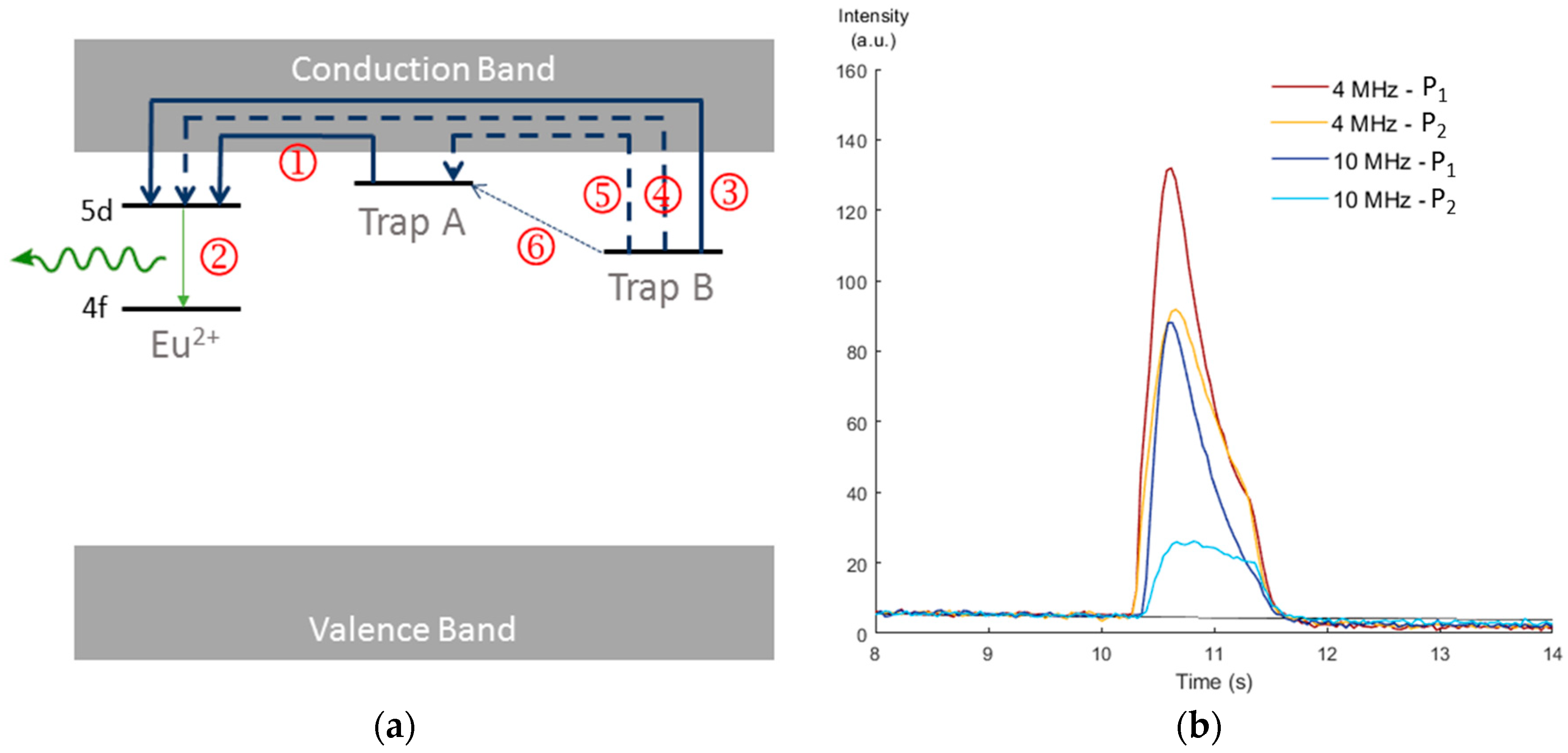
This behavior can be explained by using the so called “two trap level model” as introduced for BaSiON in [9], which models the distribution of trap levels present in the band gap by two levels: a “shallow” level A and a “deep” level B. Shown in Figure 4a, this model labels the relevant steps in the mechanism as follows:
  • 1-3-4: Thermally or mechanically assisted release of a trapped charge carrier towards the emitting center.
  • 2: Emission resulting from the arrival of a charge carrier through one of the other pathways.
  • 5: Retrapping in a shallow trap of a charge carrier previously released from a deep one.
  • 6: Mechanically assisted transfer from a deep trap to a shallow one.
The thermally assisted emptying of traps, causing the afterglow emission, happens in two phases as described by the double exponential in Equation (1). In the fast phase, mainly shallow traps A are emptied along with a small number of deep traps B, which can be understood as the detrapping probability p follows a Boltzmann law
p ~ exp(−kT/ΔE)
The detrapping probability depends on the energy barrier ΔE (corresponding to the vertical distance between the trap level and the conduction band). B traps contribute to the afterglow process on a slower timescale, since they have a larger energy barrier to overcome at a given temperature T. When the shallow traps are depleted, the afterglow enters the second (slow) phase with emission arising mainly from these deep traps. After ten minutes, only the deeper traps have not yet been fully depleted, contributing to a small, yet persistent emission intensity. When an ultrasonic stimulation is applied during the initial phase, pathway 1 causes a lot of “direct” emission and a large APL peak appears, with only a limited generation of afterglow (i.e., the tail in the APL emission peak after ending the ultrasound stimulation). The peak is thus narrower than when ultrasound is applied in a later stage, when the retrapping becomes more prominent. This can be explained as pathways 5 and 6 are initially happening at a lower rate compared to the direct recombination because their possible trapping levels are still largely occupied. These pathways become available in a later stage.
Finally, APL emission was recorded at two different ultrasonic frequencies and acoustic pressures (with P1 > P2). The resulting curves are shown in Figure 4b, showing that APL works for different ultrasonic frequencies and pressures. This provides a good indication that the APL visualization method can be used over a wide range of frequencies and, through proper calibration, for absolute measurements of ultrasonic intensities.

4. Conclusions

In conclusion, the APL visualization technique has been improved, allowing the radiation field of a transducer to be mapped in a short time. The mechanism behind this phenomenon has been explained using the two trap level model, showing that both deep and (thermally accessible) shallow traps can be addressed by an ultrasonic stimulation. This means it would be possible to use a suitable phosphor compound with a deeper overall trap distribution, thus reducing the afterglow during measurements (which acts as an interfering background for APL measurements). Finally, it was shown that APL works at frequencies between 3.3 MHz and 10 MHz. Our recent preliminary experiments indicate that the useful frequency range for APL might be even broader. Through proper calibration, the APL visualization method can be used to spatially map the absolute ultrasonic intensity in two dimensions for a range of transducers.

Supplementary Materials

The following are available online at www.APL.Ugent.be, Video: APL-3_3MHz.avi.

Author Contributions

All authors contributed to the design of the experiments. S.M. performed the experiments with the help of G.L. S.M. analyzed the data with the help of P.F.S. and M.K. S.M. wrote the draft of the paper, with all authors contributing to the final version.

Acknowledgments

Simon Michels acknowledges the financial support of Fonds voor Wetenschappelijk Onderzoek FWO-Vlaanderen (SB grant 1S33317N). The authors further acknowledge the BOF-GOA Enclose project at Ghent University.

Conflicts of Interest

The authors declare no conflict of interest.

References

  1. Dudley, N.J.; Griffith, K.; Houldsworth, G.; Holloway, M.; Dunn, M.A. A review of two alternative ultrasound quality assurance programmes. Eur. J. Ultrasound 2001, 12, 233–245. [Google Scholar] [CrossRef]
  2. Scorza, A.; Conforto, S.; D’Anna, C.; Sciuto, S.A. A Comparative Study on the Influence of Probe Placement on Quality Assurance Measurements in B-mode Ultrasound by Means of Ultrasound Phantoms. Open Biomed. Eng. J. 2015, 9, 164–178. [Google Scholar] [CrossRef] [PubMed]
  3. Van den Eeckhout, K.; Smet, P.F.; Poelman, D. Persistent Luminescence in Eu2+-Doped Compounds: A Review. Materials 2010, 3, 2536–2566. [Google Scholar] [CrossRef]
  4. Van der Heggen, D.; Joos, J.J.; Rodríguez Burbano, D.C.; Capobianco, J.A.; Smet, P.F. Counting the Photons: Determining the Absolute Storage Capacity of Persistent Phosphors. Materials 2017, 10, 867. [Google Scholar] [CrossRef] [PubMed]
  5. Chandra, V.K.; Chandra, B.P. Dynamics of the mechanoluminescence induced by elastic deformation of persistent luminescent crystals. J. Lumin. 2012, 132, 858–869. [Google Scholar] [CrossRef]
  6. Feng, A.; Smet, P.F. A Review of Mechanoluminescence in Inorganic Solids: Compounds, Mechanisms, Models and Applications. Materials 2018, 11, 484. [Google Scholar] [CrossRef] [PubMed]
  7. Kersemans, M.; Smet, P.F.; Lammens, N.; Degrieck, J.; Van Paepegem, W. Fast reconstruction of a bounded ultrasonic beam using acoustically induced piezo-luminescence. Appl. Phys. Lett. 2015, 107, 234102. [Google Scholar] [CrossRef]
  8. Zhan, T.Z.; Xu, C.-N.; Fukuda, O.; Yamada, H.; Li, C. Direct visualization of ultrasonic power distribution using mechanoluminescent film. Ultrason. Sonochem. 2011, 18, 436–439. [Google Scholar] [CrossRef] [PubMed]
  9. Botterman, J.; Van den Eeckhout, K.; De Baere, I.; Poelman, D.; Smet, P.F. Mechanoluminescence in BaSi2O2N2:Eu. Acta Mater. 2012, 60, 5494–5500. [Google Scholar] [CrossRef]
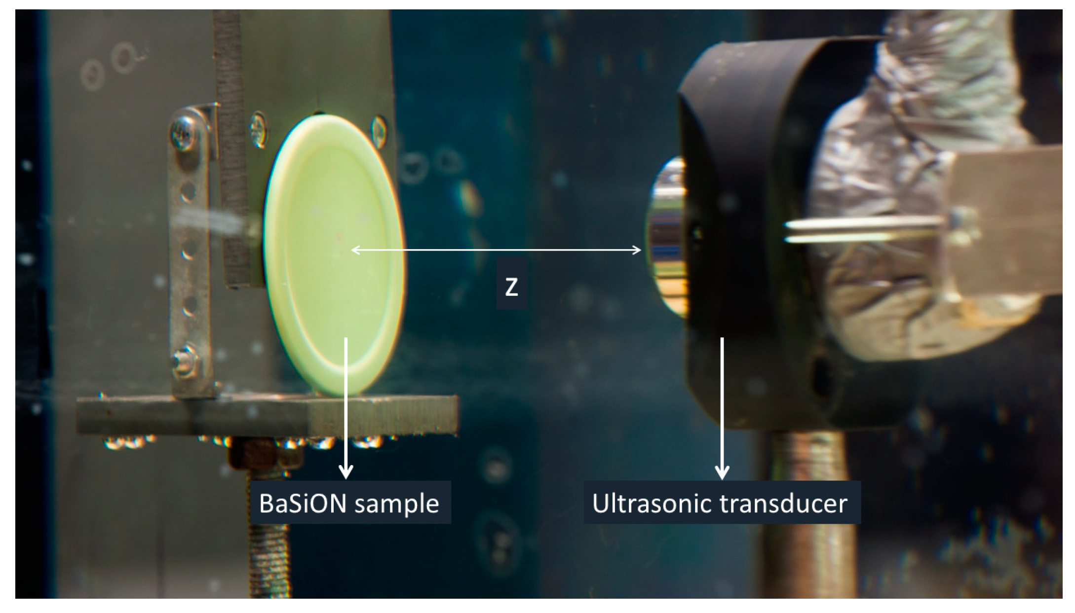
Figure 1. The experimental setup used for the APL visualization experiments.
Proceedings 02 00491 g001
Figure 2. Comparison of the obtained APL cross sectional images with the original experimental setup (top) and the new one (bottom). The distance between the transducer head and the phosphor layer is indicated by z.
Proceedings 02 00491 g002
Figure 3. APL experiments at different delay times. The inset shows the total emitted light during each experiment, with respect to the afterglow (AG).
Proceedings 02 00491 g003
Figure 4. (a) The two trap level model for ML/APL in BaSiON. The different numbers are explained in the main text. (b) APL emission curves at two different ultrasonic frequencies and pressures.
Proceedings 02 00491 g004
Publisher’s Note: MDPI stays neutral with regard to jurisdictional claims in published maps and institutional affiliations.