Proceeding Paper

Early-Stage Damage Detection in Advanced Multifunctional Aerospace Composites Using Embedded Carbon Nanotubes and Flocked Carbon Fibers †

1
The U.S. Army Research Laboratory, Aberdeen Proving Ground, MD 21005, USA
2
Department of Mechanical Engineering, University of Massachusetts Dartmouth, North Dartmouth, MA 02747, USA
*
Author to whom correspondence should be addressed.
Presented at the 18th International Conference on Experimental Mechanics, Brussels, Belgium, 1–5 July 2018.
Proceedings 2018, 2(8), 490; https://doi.org/10.3390/ICEM18-05386
Published: 24 June 2018
(This article belongs to the Proceedings of The 18th International Conference on Experimental Mechanics)

Abstract

:
Early-stage damage detection could provide better reliability and performance and a longer lifetime of materials while reducing maintenance time of a variety of structures and systems. We investigate the early-stage damage formation and damage evolution in advanced multi-functional laminated aerospace composites embedded with a very small amount of carbon nanotubes (CNTs) in the matrix material and short carbon fibers along the Z-direction to reinforce the interlaminar interfaces. The three-dimensional (3-D) conductive network formed by the CNTs and the flocked carbon fibers allows for sensitive in-situ damage detection in materials in addition to providing improved mechanical properties such as superior fracture toughness for damage tolerance. We optimize several parameters such as fiber length, diameter, and density to generate an effective 3-D electrical conductive network, and characterize the responses of these composites under mechanical loading to investigate damage formation and evolution, advancing science and technology towards superior damage-tolerant and zero-maintenance structural materials.

1. Introduction

Fiber reinforced polymer (FRP) composites have emerged as critical structural materials for aerospace applications due to outstanding fatigue performance, high specific stiffness and strength, and low density. However, even microscale damage such as fiber debonding, delamination, matrix cracking, and fiber breakage in laminated composites could lead to a compromise in structural integrity of the material, thus raising a critical need to monitor the wellness state of the structure. Damage detection in the early stages of formation could provide better reliability and performance and a longer lifetime of the structure while reducing maintenance time. This has led to an increased scientific and technical quest for physically stable, quick responding, and cost effective strain sensing materials, devices, and techniques with high sensitivity over a broad range of the practical levels of strain experienced by a structure or system of interest. Currently, metal foil strain gauges and optical fiber sensors are the most popular strain sensing mechanisms. Albeit high stability and cost-effectiveness, metal foil gauges can only be surface-mounted and have a low gauge factor [1]. The requirement of expensive instrumentation, lack of sensitivity to cracks parallel to the fiber orientation and the potential of crack initiation are serious challenges posed by the optical fiber sensor technique which are yet to be overcome [2,3,4,5]. Carbon nanotubes (CNTs), with the high aspect ratio and superior electrical, thermal, and mechanical properties have attracted much attention for sensing applications [6,7,8] as a variety of CNT configurations have shown stable and improved piezoresistive behavior [9,10,11,12,13,14].
The current work focuses on in-situ detection of early-stage damage formation and evolution in laminated glass fiber reinforced composite with superior fracture toughness for damage tolerance through the embedding of a very small amount of multi-wall CNTs in the matrix material and flocking short carbon fibers between the laminates. Earlier studies have demonstrated detectable change in the resistance of the composite made of CNTs and epoxy in response to mechanical loading [15]. Much is yet to be investigated regarding glass fiber composites with 3-D conductive network under tensile loading conditions. We optimize several parameters such as fiber length, diameter, and density to generate effective 3-D electrical conductive network, and measure electrical response under mechanical tensile loading for in-situ damage detection, getting us closer towards the realization of superior damage-tolerant and zero-maintenance structural materials.

2. Materials and Methods

2.1. Composite Coupon Fabrication

The glass fiber composite using the Thermoset epoxy 2000 system (obtained from Fiberglast, Brookville, OH, USA). Coupons of 3 mm thick and 150 × 150 mm2 were fabricated to obtain 5 test samples for measuring electrical and mechanical properties under quasi-static loading conditions. The epoxy which comes in two parts (resin and hardener) was mixed in the ratio is 1:0.27 (resin:hardener). The weight percentage of the CNTs used were 0.3% (for composites without carbon fiber flocking) and 0.1% (for composites with carbon fiber flocking), based on the total mass of epoxy resin and hardener. After initially hand-mixing the epoxy and CNTs for 5 min, the mixture was transferred to an ice bath to perform combined ultrasonication and shear mixing for one hour, with careful monitoring of the temperature of the mix to avoid reaching the flash point of epoxy. Then this mix was moved to a vacuum chamber to degas all air bubbles after which the hardener was added and shear mixed for 5 min. To remove any entrapped air during the hardener mixing, the mixture was vacuumed again and set aside. Further, 150 × 150 mm2 woven glass fabrics are put through a standard vacuum infusion process to infuse the prepared epoxy/CNT mix through the stacked glass fabric layers. After curing at room temperature for 48 h the unflocked samples were ready. In case of carbon fiber flocked composites, first the glass fabrics are wet with epoxy and then short carbon fibers of 350 µm are flocked using wet flocking technology developed at University of Massachusetts, Dartmouth (UMASSD) to obtain coupons with four different flock densities, 2000, 1500, 1000 and 500 fibers/mm2.

2.2. Electromechanical Characterization

Rectangular specimens with dimensions of 125 mm length, 19 mm width, and 4 mm thickness were tested under tensile loading conditions to obtain the average Young’s moduli of the specimens for carbon fiber flock length size of 350 microns for four different flock densities (500, 1000, 1500, and 2000 fibers/mm2). Volume resistivity measurements of composites were obtained using the four circumferential resistance measurement (FCRP) system as shown in Figure 1. A constant DC current was provided by the current source (Keithley Instruments, Cleveland, OH, USA, Model 6220). With a distance of 25 mm between the current probes and 12.5 mm between the voltage probes, the voltage at each inner probe was captured by two electrometers (Keithley Instruments, Model 6514. The voltage difference between two electrometers was then obtained using a digital multimeter (Keithley Instruments, Model 2000 DMM). The very high impedance of electrometers prevent current leakage into the multimeter. LabVIEW was used for data acquisition from the multimeter. Considering Ohm’s law:
R = V I
V represents the voltage difference between the inner probes, I is the constant current, and R is the resistance of composite between inner probes. A percentage change in resistance is simply calculated using this as reference (RRo)/Ro × 100.

3. Results and Discussion

Figure 2 shows the dependence of stress and electrical resistance on strain. The three distinct sections of the graph may be explained as follows: Section-I demonstrated no noticeable change in electrical resistance with very little change in stress values. Section-II shows linear change in electrical resistance as the load increases, which might be an indicator of the initiation and propagation of damage inside the material. Section-III indicates a decrease in the slope the electrical resistance compared to Section-II, probably due to the reduction of cross sectional area associated with the non-linear deformation of the stress strain curve, pushing the conductive network closer together at the same time the tensile load is pulling it apart.
The electro-mechanical response of carbon fiber flocked composite with a flock density of 1500 fibers/mm2 is shown in the Figure 3. Again, the plot consists of three distinct sections. Section-I shows a slight increase in resistance as the CNTs and the carbon fiber change their orientation and tend to separate, causing a decrease in electron hopping between conductive elements. Section-II, much different than that of the unflocked composite from Figure 2, indicates a steady increase in resistance which may be due carbon fiber pull out between the laminates. Section-III shows increasing slope of resistance change compared to that of the unflocked sample, unlike the decreasing slope of the resistance change in Figure 2. Thus flocked carbon fibers seem to have significant influence on the change in damage growth within the composite.
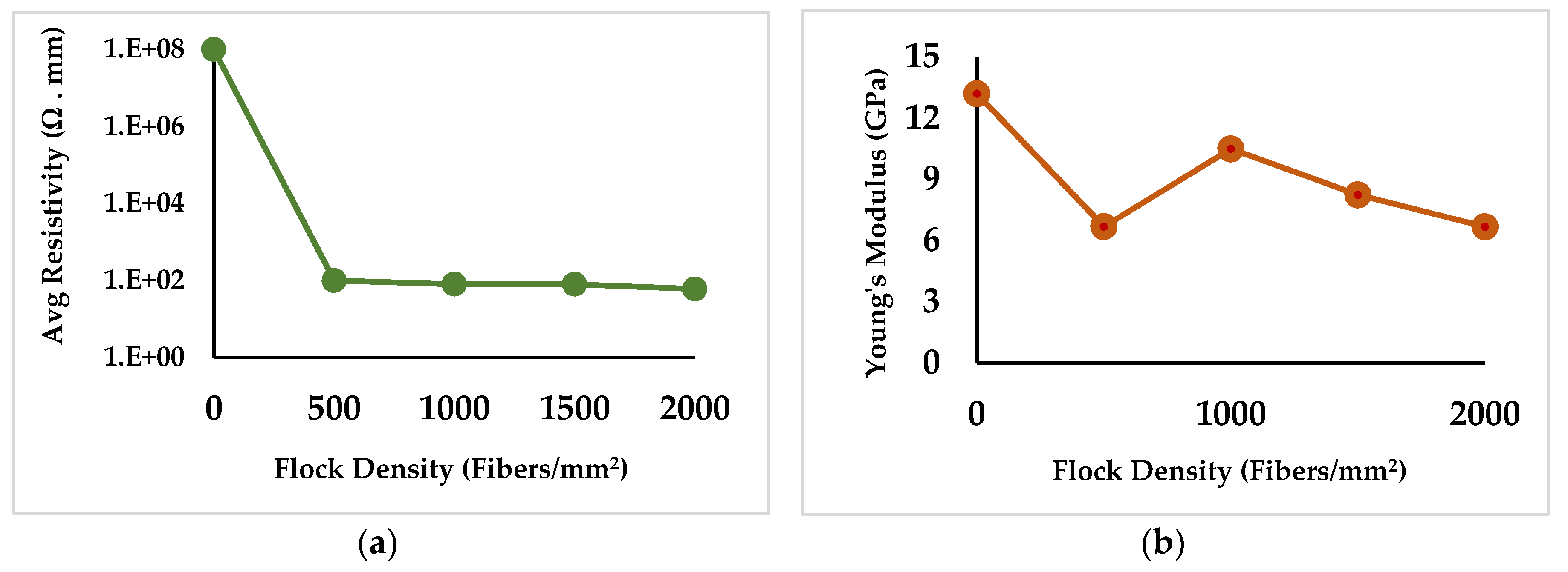
The volume resistivity values of glass fiber laminated composites of without flocking and carbon fiber flock density of various densities are shown in Figure 4a. The addition of carbon fibers with flocking between laminates drastically reduced the volume resistivity. The carbon fibers generated an effective three-dimensional conductive network neighboring CNTs in the composite system. Figure 4b shows the calculated Young’s modulus for each sample. As seen, the 500 flock density is an outlier and further investigation for this case is in progress. With 1000 carbon fiber flock per square millimeter a decrease of 3 GPa is observed in the Young’s modulus. Flock decreases the stiffness of the composite (as the carbon flock is normal to the loading direction) but as demonstrated in earlier studies, it does increase the overall fracture toughness [16,17].
In conclusion, we have optimized several parameters such as fiber length, diameter, and density to generate an effective 3-D electrical conductive network formed by the CNTs and the flocked carbon fibers for sensitive in-situ damage detection in materials in addition to providing improved mechanical properties such as superior fracture toughness for damage tolerance. We have characterized the electromechanical responses of these composites under mechanical loading to investigate damage formation and evolution. Further characterization and testing and correlation of data obtained from a variety of techniques is underway and is highly promising for superior damage-tolerant and zero-maintenance structural materials.

Author Contributions

V.C., A.H., and H.M. conceived and designed the experiments; R.S., J.O. fabricated the composites and performed electromechanical characterization; L.N. and M.C. performed more mechanical and electrical testing, L.N. wrote the paper.

Acknowledgments

This work is supported by a collaborative research agreement between the U.S. Army Research Laboratory and the University of Massachusetts, Dartmouth (W911NF-17-2-0198).

Conflicts of Interest

The authors declare no conflict of interest.

References

  1. Hehr, A.; Schulz, M.; Shanov, V.; Song, Y. Embedded carbon nanotube thread piezoresistive strain sensor performance. Sensor Rev. 2014, 34, 209–219. [Google Scholar]
  2. Li, Z.; Dharap, P.; Nagarajaiah, S.; Barrera, E.V.; Kim, J.D. Carbon nanotube film sensors. Adv. Mater. 2004, 16, 640–643. [Google Scholar] [CrossRef]
  3. Li, X.; Levy, C.; Elaadil, L. Multiwalled Carbon Nanotube film for strain sensing. Nanotechnology 2008, 19, 045501. [Google Scholar] [CrossRef] [PubMed]
  4. Hehr, A.; Schulz, M.; Shanov, V.; Song, Y. Micro-crack detection and assessment with embedded carbon nanotube thread in composite materials. Struct. Health Monit. 2014, 13, 512–524. [Google Scholar] [CrossRef]
  5. Song, Y.; Hehr, A.; Shanov, V.; Alvarez, N.; Kienzle, N.; Cummins, J.; Koester, D.; Schulz, M. Carbon nanotube sensor thread for distributed strain and damage monitoring on IM7/977-3 composites. Smart Mater. Struct. 2014, 23, 075008. [Google Scholar] [CrossRef]
  6. Li, C.; Chou, T.-W. Modeling of damage sensing in fiber composites using carbon nanotube networks. Comps. Sci. Technol. 2008, 68, 3373–3379. [Google Scholar] [CrossRef]
  7. Park, J.-M.; Kim, D.-S.; Kim, S.-J.; Kim, P.-G.; Yoon, D.-J.; De Veries, K. L. Inherent sensing and interfacial evaluation of carbon nanofiber and nanotube/epoxy composites using resistance measurement and micromechanical technique. Compos. Part B 2007, 38, 847–861. [Google Scholar] [CrossRef]
  8. Saafi, M. Wireless and embedded carbon nanotube networks for damage detection in concrete structures. Nanotechnology 2009, 20, 395502. [Google Scholar] [CrossRef] [PubMed]
  9. Loh, K.J.; Kim, J.; Lynch, J.P.; Kam, N.W.S.; Kotov, N. Multifunctional layer-by-layer CNT-polyelectrolyte thin films for strain and corrosion sensing. Smart Mater. Struct. 2007, 16, 429. [Google Scholar] [CrossRef]
  10. Alexopoulos, N.D.; Jaillet, C.; Zakri, C.; Poulin, P.; Kourkoulis, S.K. Improved strain sensing performance of glass fiber polymer composites with embedded pre-stretched polyvinyl alcohol–carbon nanotube fibers. Carbon 2013, 59, 65–75. [Google Scholar] [CrossRef]
  11. Sebastian, J.; Schehl, N.; Bouchard, M.; Boehle, M.; Li, L.; Lagounov, A.; Lafdi, K. Health monitoring of structural composites with embedded carbon nanotube coated glass fiber sensors. Carbon 2014, 66, 191–200. [Google Scholar] [CrossRef]
  12. Zhang, R.; Deng, H.; Valenca, R.; Jin, J.; Fu, Q.; Bilotti, E.; Peijis, T. Strain sensing behaviour of elastomeric composite films containing carbon nanotubes under cyclic loading. Compos. Sci. Technol. 2013, 74, 1–5. [Google Scholar] [CrossRef]
  13. De la Vega, A.; Sumfleth, J.; Wittich, H.; Schulte, K. Time and temperature dependent piezoresistance of carbon nanofiller/polymer composites under dynamic load. J. Mater. Sci. 2012, 47, 2648–2657. [Google Scholar] [CrossRef]
  14. Zetina-Hernández, O.; Duarte-Aranda, S.; May-Pat, A.; Canché-Escamilla, G.; Uribe-Calderon, J.; Gonzalez-Chi, P.I.; Avilés, F. Coupled electro-mechanical properties of multiwall carbon nanotube/polypropylene composites for strain sensing applications. J. Mater. Sci. 2013, 48, 7587–7593. [Google Scholar] [CrossRef]
  15. Cardoso, S.M.; Chalivendra, V.B.; Shukla, A.; Yang, S. Damage detection of rubber toughened nanocomposites in the fracture process zone using carbon nanotubes. Eng. Fract. Mech. 2012, 96, 380–391. [Google Scholar] [CrossRef]
  16. Pinto, M.; Chalivendra, V.B.; Kim, Y.K.; Lewis, A. Effect of Surface Treatment and Z-axis Reinforcement on the Interlaminar Fracture of Jute/Epoxy Laminated Composites. Eng. Fract. Mech. 2013, 114, 104–114. [Google Scholar] [CrossRef]
  17. Yang, S.; Chalivendra, V.B.; Kim, Y.K. Fracture and impact characterization of novel auxetic Kevlar/Epoxy laminated composites. Compos. Struct. 2017, 168, 120–129. [Google Scholar] [CrossRef]
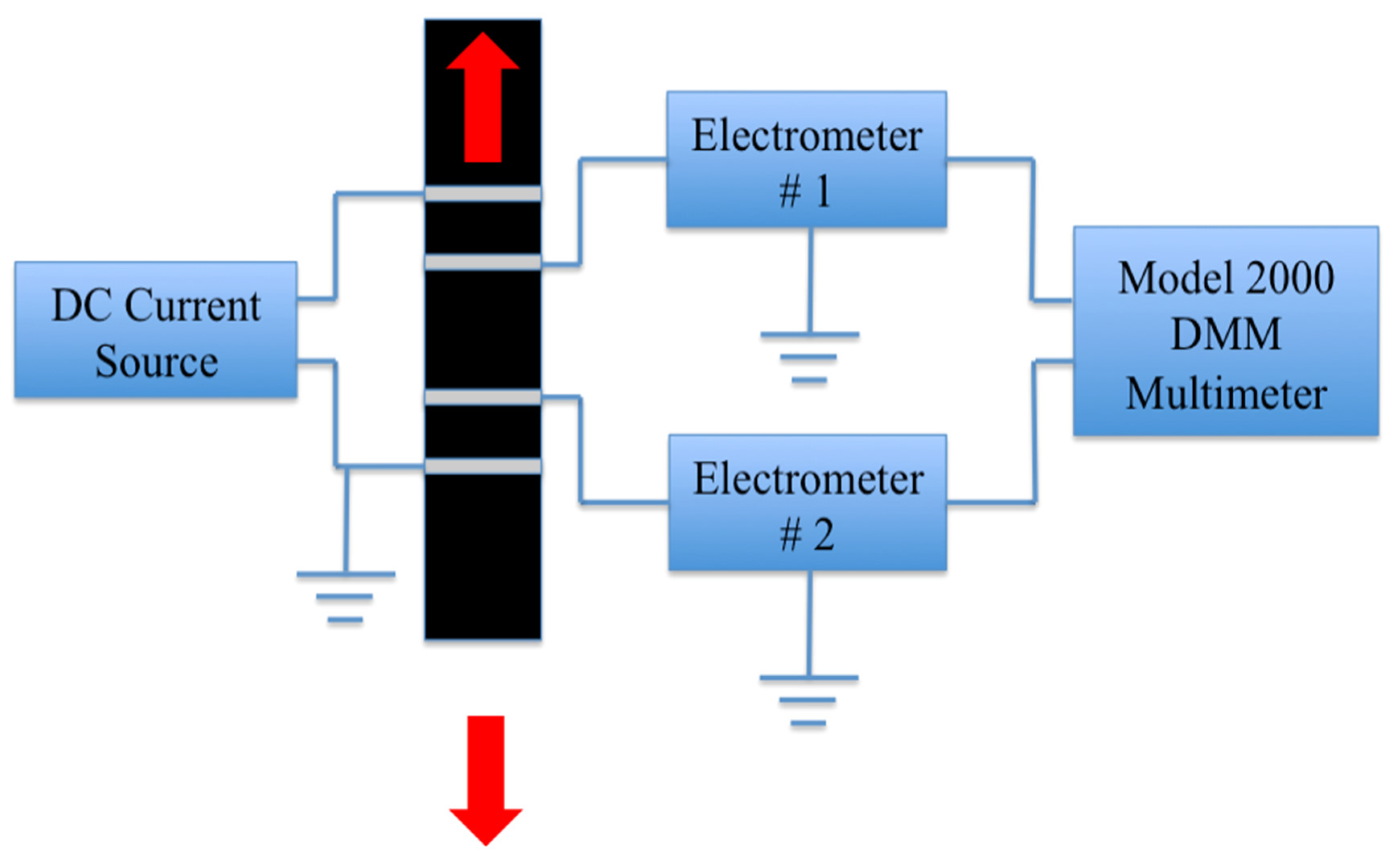
Figure 1. Schematic of four circumferential probe measurement system for test specimen under tensile loading conditions.
Proceedings 02 00490 g001
Figure 2. The electro-mechanical response of a glass fiber CNT .3%wt reinforced composite with no flock.
Proceedings 02 00490 g002
Figure 3. The stress strain curve of a glass fiber CNT. 1 wt % reinforced composite with 350 μm flock length and 1500 (fibers/mm2) flock density.
Proceedings 02 00490 g003
Figure 4. Impact of flocking densities on (a) Volume resistivity; (b) Young’s Modulus.
Proceedings 02 00490 g004
Publisher’s Note: MDPI stays neutral with regard to jurisdictional claims in published maps and institutional affiliations.