1. Introduction
Mass and heat transport in geothermal reservoirs is controlled by interconnected conductive fractures that are essential to ensure adequate supply of geothermal fluids and efficient thermal operation of the wells. In order to better understand the fluid flow patterns in the reservoirs, electrical resistivity methods are commonly used (e.g., [
1,
2,
3]) because electrical resistivity has been shown to be sensitive to changes in fluid conductivity and water content in reservoirs (e.g., [
4,
5]). However, modelling fractures deep in the ground is a difficult task and none of the geophysical exploration methods currently used to explore geothermal reservoirs is capable of providing an accurate high-resolution model of the reservoirs at the required scale, depth and cost for running the power plants in an optimal way.
This project focuses on investigating the possibility of using geothermal steel casings to transfer electric current deeper into the ground during resistivity surveys. The current and potential electrodes are generally arranged in a linear array in resistivity surveys but other set-ups can be used such as the cross-well method where one current and one voltage electrode is placed inside a well and the other electrodes are placed inside another well. This method can provide detailed information about the resistivity distribution between the wells as demonstrated by Daniels and Dyck [
6]. Another possibility is to use the Mise-A-La-Masse method which involves connecting the charged current electrode to a conductive structure that goes deep into the surface, such as the steel casing of a geothermal well. Then, the other current electrode is usually placed far from the survey area and the electric potentials are measured using one fixed electrode and one electrode that is moving radially around the borehole. For example, a Mise-A-La-Masse experiment was used to define the boundaries of a geothermal reservoir in Hawaii using the casing as an electrode and measuring electric potentials to a distance of 2 km from the well [
7]. Additionally, Mise-A-La-Masse was used to determine new production targets in the Sibayak field in Indonesia [
8]. In this study, the cross-well method is used in conjunction with the Mise-A-La-Masse method, i.e., steel casings are used as electrodes and the resistivity is studied between well pairs.
Measurements are performed at Reykjanes geothermal reservoir on several wells including the IDDP-2/RN-15 well that reached supercritical temperatures once it was deepened down to 4.7 km in January 2017 as part of the Iceland Deep Drilling Project (IDDP) [
9]. A direct current resistivity survey using casings as electrodes is performed and the electric potentials between casing pairs are measured. Two 12 V batteries are connected in series with the positive terminal connected to one casing and the negative terminal connected to another casing in order to inject current from one well to the other. A resistor is added to the circuit as well as an ammeter to measure the electric current and a voltmeter to measure the electric potential difference between the casings. One of the wells tested, well IDDP-2/RN-15 is not connected to any surface pipelines, thus ensuring the current only flows between the wells through the ground. However, well pairs connected vie surface pipelines are studied as well.
In addition, surface electrodes are used for comparison to using the steel casings as electrodes to infer whether the current is travelling deeper and giving more information regarding the flow connectivity of the fractures between wells when the steel casings are used instead of surface electrodes. Gaining knowledge of the fracture connectivity is extremely valuable to design the recovery strategy appropriately, optimize the placing of injection or production wells and increase the overall efficiency of the power production.
2. Materials and Methods
In electrical resistivity surveys, the resistivity of the subsurface is calculated from electrical measurements. First, a direct current is sent into the ground through current electrodes and the voltage differences between voltage electrodes are recorded. Then, the input current and measured voltage difference give information about the subsurface resistivity. Electrical current moving through the reservoir passes mainly through fluid-filled fractures and pore spaces because the rock itself is normally a good insulator. Hence, resistivity measurements can give information about the fracture connectivity.
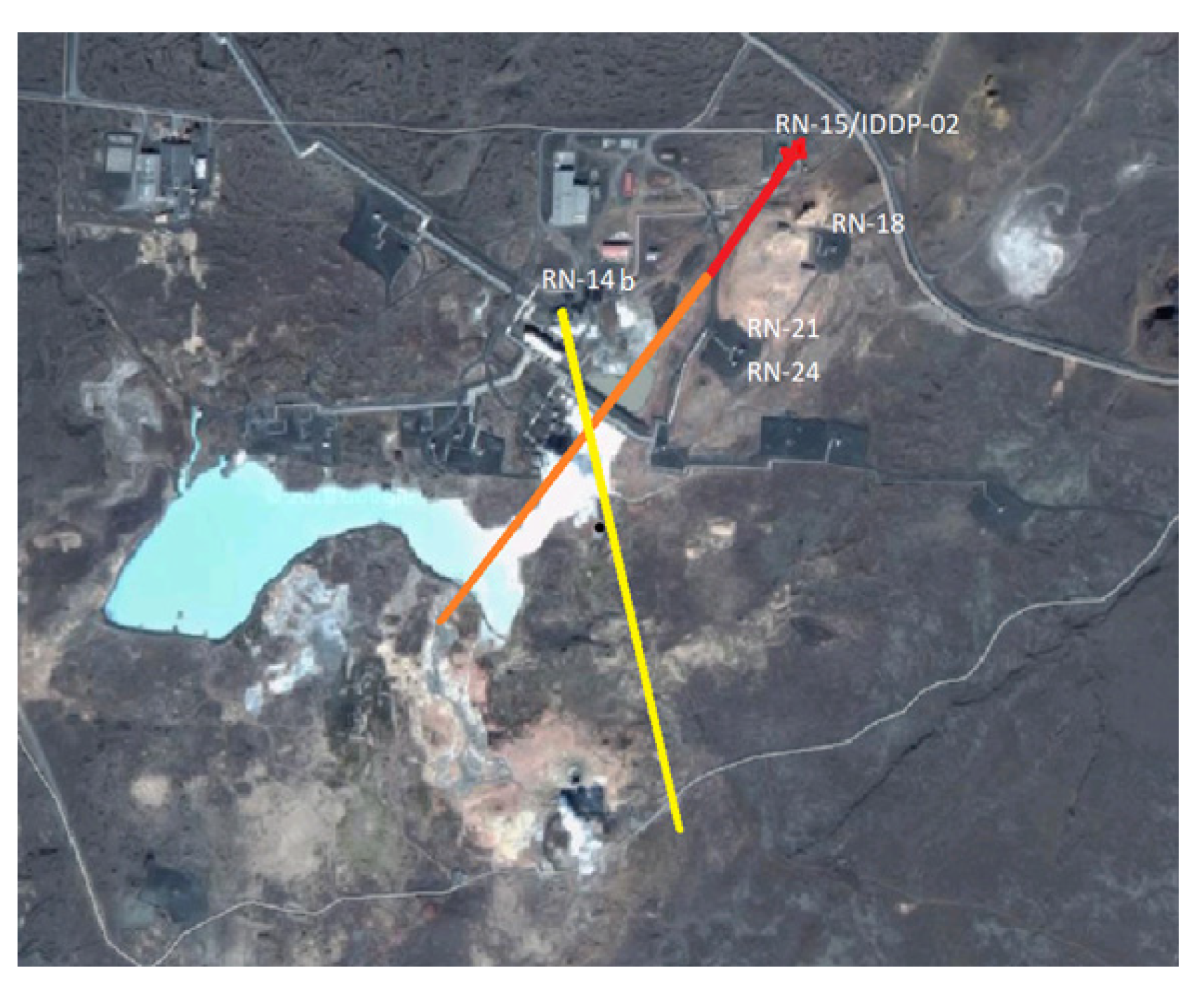
An overview of Reykjanes geothermal field and locations of wells IDDP-2, RN-14b, RN-18, RN-21 and RN-24 are shown in
Figure 1. Wells IDDP-2 and RN-14b are directionally drilled (approximate tracks are shown in
Figure 1) and wells RN-18, RN-21 and RN-24 are all drilled vertically. The depth of the wells in addition to the size and depth of the production casings are shown in
Table 1. Once well RN-15/IDDP-2 was deepened during the Iceland Deep Drilling Project (IDDP), it was disconnected from the surface pipelines. Therefore, during the following experiments, well IDDP-2 is not connected to the other wells via surface pipelines.
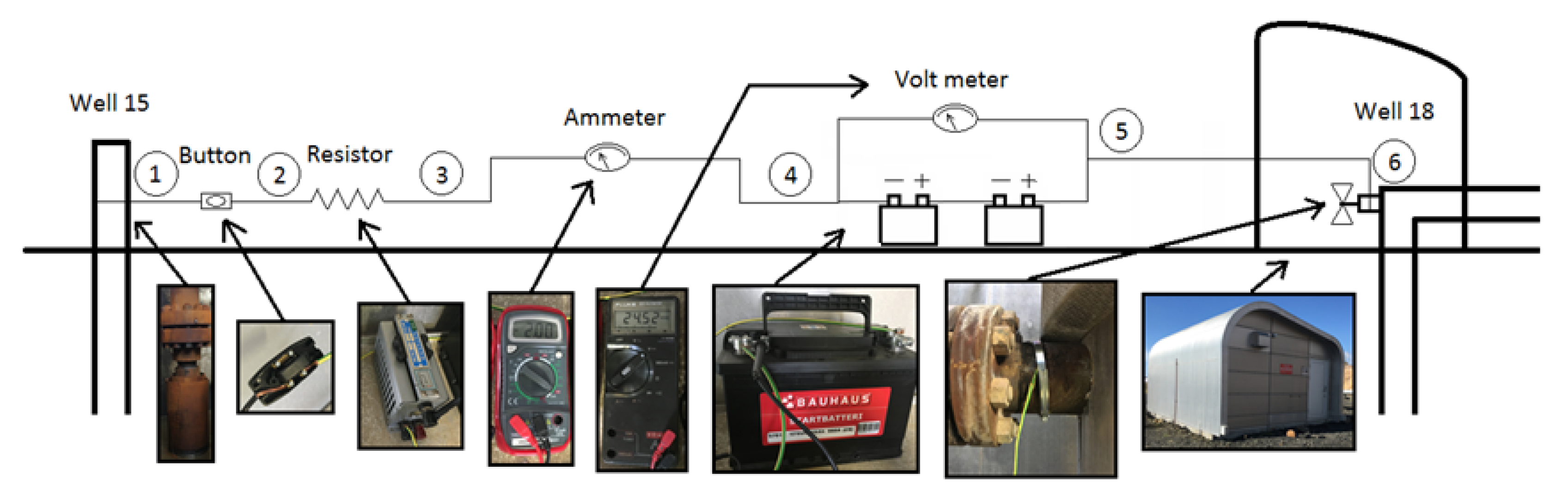
The setup for the measurements performed at the reservoir are shown in
Figure 2 for wells IDDP-2 and RN-18. The same setup is used for the other well pairs tested. First, an electric wire is attached to the production casing of well IDDP-2 with a hose clamp. Part of the casing surface is removed using a hand file and the resistance from the wire to the production casing is tested to assure a good electrical connection. Next, a button is attached to the wire from well IDDP-2 to ease the process of connecting and disconnecting the electric circuit. Then, a resistor is attached to the circuit to control the amount of current flowing through the circuit and the resistor’s resistance is measured as 10.6 ohm.
An ammeter is added to measure the current flowing through the circuit and a voltmeter to measure the electric potential difference over two batteries. The batteries were 12 V 72 Ah batteries and they are connected in series. The electric wire coming from well IDDP-2 is connected to the negative terminal and the positive terminal is connected to a valve on well RN-18 using a hose clamp after removing some of the surface of the valve to ensure a good electrical connection. The valve on RN-18 connects to the 13 3/8 inch production casing that goes down to a depth of 600 m. The same set-up is used for measurements on other well pairs and each time the resistance from the production casing to the wire connecting to it is measured to ensure a good electrical connection.
Ohm’s Law defines the relationship between the electric potential (voltage) across an ideal conductor, the current flowing through it and the resistance of the conductor as:
where
V is the voltage [V],
I is the current [A] and
R is the resistance [ohm]. Hence, the ammeter is used to measure the current, the voltmeter is used to measure the electric potential and the total resistance is calculated using Equation 1. Then, the ground resistance between well pairs is calculated by subtracting the resistance of the resistor in the circuit that is equal to 10.6 ohm.
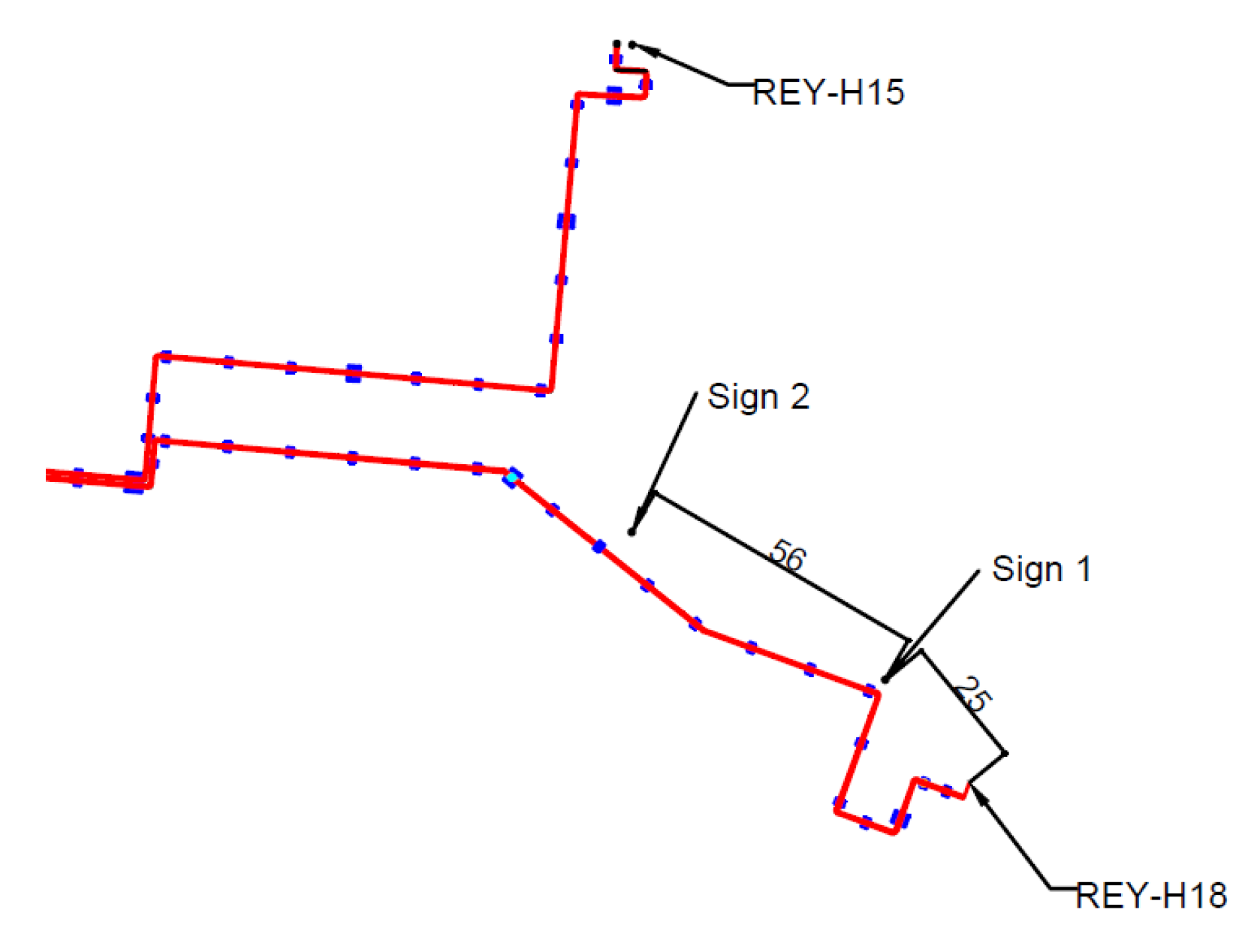
The same method is used when surface electrodes are studied except that three batteries are used instead of two to get a higher current and the resistor is 10.8 ohm. Two steel signs (Sign 1 and Sign 2) going below the frost line are used as surface electrodes to provide a good connection into the ground around them. The resistance is measured between well RN-18 and Sign 1, between Sign 1 and Sign 2, and between well RN-18 and Sign 2. The distance [m] of the signs from RN-18 is shown in
Figure 3.
Additionally, measurements are done to test whether the electric current is flowing from the production casing to the anchor casing and from there into the ground or if it is going through the production casing deeper into the ground.
3. Results
The resistance between a total of seven well pairs are studied. Well IDDP-2 is used for four of the tests because well IDDP-2 is not connected to any other wells via surface pipelines. Hence, the current travels from one casing to another through the ground instead of possibly traveling through the pipelines on the surface. Other wells tested are connected to separator stations at the power plant so it is possible for the current to travel between these well casings through the surface pipelines. The following sections show results for the resistance measurements between well pairs as well as measurements where surface electrodes are used.
3.1. Measurements between Well Pairs
Table 2 summarizes the measurement results for wells IDDP-2, RN-14b, RN-18, RN-21 and RN-24 and the calculated resistance after subtracting the 10.6 ohm resistance of the resistor included in the circuit. The resistance for well IDDP-2 that is not connected to the other wells via surface pipelines ranges between 2.30 and 4.56 ohm. This low resistance indicates that the current is traveling through water-filled fractures from one casing to another. The resistance is also in agreement with the distance between well pairs in the sense that the further the wells are from each other, the higher the resistance.
However, the change in resistance is not proportional to the distance between well-heads. For example, if the current traveling between wells IDDP-2 and RN-18 is going through the same type of medium as when it travels between wells IDDP-2 and RN-14b, the resistance between the latter well-pair should be approximately 2.4 times the resistance between wells IDDP-2 and RN-18 because that is the difference in distance between well-heads. The difference in resistance is only a factor of 2, indicating that the current is traveling deeper along the production casing towards well RN-14b. The same goes for the other wells tested with well IDDP-2.
Well IDDP-2 is drilled directionally in a direction going closer towards wells RN-14b, RN-21 and RN-24 so it is likely that the current is traveling deeper into the ground towards these wells instead of traveling along the surface. However, it is difficult to estimate how deep the current is traveling as several factors other than the distance affect the measured resistance. These factors include the ground resistivity affected by rock type, temperature, salinity and water content as well as the contact resistance between the soil and the electrode (i.e., casing) and resistance between the casing and the wire (usually a negligible part of the total resistance).
The last three well pairs in
Table 2 are connected via surface pipelines and the low resistance measured between these well indicates that the current is traveling through the pipelines instead of going through the ground. In order to further study if the current is traveling through the surface pipelines, the resistance is measured between RN-14b and a valve located on the surface pipeline in the middle between well RN-18 and the steam separator. The measured resistance is 2.03 ohm, which is in good agreement with the resistance measured as 3.00 ohm between well RN-14b and RN-18, if it is assumed that the current is flowing through the surface pipelines between the wells. The results for the resistance measured between well RN-14b and a valve on the surface pipeline close to the steam separator also indicate that the current is traveling through the surface pipelines instead of going through the ground.
For wells not connected via surface pipelines, the possibility of the current flowing from the production casing to the anchor casing and from there along the surface is tested as well. The electrical connectivity between the anchor casing and production casing of well RN-21 is measured to investigate whether the electric current flows from the production casing to the anchor casing. The resistance between the production casing and the anchor casing is high and the resistance between well RN-14b and the anchor casing of well RN-21 is high as well, or 9.39 ohm. Thus, the measurements indicate that the electric current is not flowing through the anchor casing in the experiments above and that the current is likely flowing deeper along the production casing.
3.2. Surface Electrodes
Surface electrodes are tested to further study whether the current between well pairs is traveling close to the surface. Steel signs (Sign 1 and Sign 2 shown in
Figure 3) going below the frost line are used as surface electrodes to provide good connection into the ground around it. In order to get a higher current three 12 V batteries are used instead of two. The results are shown in
Table 3. The calculated resistance between Sign 1 and Sign 2 is higher than between RN-18 and Sign 1 as expected since the distance between the two sings is larger than from RN-18 to Sign 1 and the casing of RN-18 conducts the current deeper into the ground. The resistance from RN-18 to Sign 1 added to the resistance from Sign 1 to Sign 2 is 319.3 ohm which is in good agreement with the measured resistance between RN-18 and Sign 2, equal to 324.7 ohm. Some difference could be explained by the current travelling directly towards Sign 2 from RN-18 instead of going through Sign 1 first. Also, the current likely travels closer to the surface from Sign 1 to Sign 2 instead of being conducted deeper into the ground through the casing of RN-18 to Sign 2. The high resistance measured when surface electrodes are used further supports the assumption that the current is traveling through the production casing deeper into the ground when the casing are used as electrodes than when surface electrodes are used.
4. Discussion
This study tests the possibility of using steel casings as electrodes in order to get the current deeper into the ground in a cross-well resistivity study. The resistance measured between well pairs where one well is not connected to the other via surface pipelines indicate that the current is traveling deeper into the ground than when surface electrodes are used. Additionally, the importance of having the well casings used in the resistivity study not connected via surface pipelines is demonstrated by measurements indicating that the current travels through surface pipelines if they connect the two casings. When at least one well is not connected to the surface pipelines, the current seems to be traveling through the ground from one well to the other. Next steps include testing this concept further by measuring the resistance between more well pairs not connected via surface pipelines. Additionally, more measurements will be performed of the resistance at several points along the surface pipelines for those well pairs that are connected.
Author Contributions
L.M. and M.T.J. designed and performed the experiments and analyzed the data; L.M. wrote the paper.
Acknowledgments
Gratitude goes to the Iceland Research Fund for funding this study.
Conflicts of Interest
The authors declare no conflict of interest. The founding sponsors had no role in the design of the study; in the collection, analyses, or interpretation of data; in the writing of the manuscript, and in the decision to publish the results.
References
- Soengkono, S. Geophysical techniques for low enthalpy geothermal exploration in New Zealand. Preview 2011, 2011, 37–40. [Google Scholar] [CrossRef]
- Arnason, K.; Karlsdottir, R.; Eysteinsson, H.; Flovenz, G.; Gudlaugsson, S. The Resistivity Structure of High-Temperature Geothermal Systems in Iceland. In Proceedings of the Short Course III on Exploration for Geothermal Resources, organized by UNU-GTP and KenGen, Lake Naivasha, Kenya, 24 October–17 November 2008. [Google Scholar]
- Harthill, N. A quadripole resistivity survey of the Imperial Valley, California. Geophysics 1978, 43, 1485–1500. [Google Scholar] [CrossRef]
- Binley, A.; Giorgio, C.; Middleton, R.; Winship, P. Vadose zone flow model parameterisation using cross-borehole radar and resistivity imaging. J. Hydrol. 2002, 267, 147–159. [Google Scholar] [CrossRef]
- Yeh, T.-C.J.; Liu, S.; Glass, R.J.; Baker., K.; Brainard, J.R.; Alumbaugh, D.L.; LaBrecque, D. A geostatistically based inverse model for electrical resistivity surveys and its applications to vadose zone hydrology. Water Resour. Res. 2002, 38, 12. [Google Scholar] [CrossRef]
- Daniels, J.J.; Dyck, A.V. Borehole resistivity and electromagnetic methods applied to mineral exploration. IEEE Trans. Geosci. Remote Sens. 1984, 22, 8087. [Google Scholar] [CrossRef]
- Kauahikaua, J.; Mattice, M.; Jackson, D. Mise-a-la-masse mapping of the HGP-A geothermal reservoir, Hawaii. In Proceedings of the Geothermal Resources Council 1980 Annual Meeting, Salt Lake City, UT, USA, 9–11 September 1980. [Google Scholar]
- Supriyanto, S.; Daud, Y.; Sudarman, S.; Ushijima, K. Use of a Mise-a-la-Masse Survey to Determine New Production Targets in Sibayak Field, Indonesia. In Proceedings of the Proceedings World Geothermal Congress 2005, Antalya, Turkey, 24–29 April 2005. [Google Scholar]
- Fridleifsson, G.O.; Elders, W.A.; Zierenberg, R.A.; Stefansson, A.; Fowler, A.P.G.; Weisenberger, T.B.; Hardarson, B.S.; Mesfin, K.G. The Iceland Deep Drilling Project 4.5 km deep well, IDDP-2, in the seawater-recharged Reykjanes geothermal field in SW Iceland has successfully reached its supercritical target. Sci. Dril. 2017, 23, 1–12. [Google Scholar] [CrossRef]
| Publisher’s Note: MDPI stays neutral with regard to jurisdictional claims in published maps and institutional affiliations. |
© 2018 by the authors. Licensee MDPI, Basel, Switzerland. This article is an open access article distributed under the terms and conditions of the Creative Commons Attribution (CC BY) license (https://creativecommons.org/licenses/by/4.0/).

