Proceeding Paper

Experimental and Numerical Analysis of Timber I-Joists with Cut-Outs †

Faculty of Engineering Technology, Hasselt University, Martelarenlaan 42, 3500 Hasselt, Belgium
*
Author to whom correspondence should be addressed.
Presented at the 18th International Conference on Experimental Mechanics (ICEM18), Brussels, Belgium, 1–5 July 2018.
Proceedings 2018, 2(8), 463; https://doi.org/10.3390/ICEM18-05375
Published: 20 June 2018
(This article belongs to the Proceedings of The 18th International Conference on Experimental Mechanics)

Abstract

:
This contribution presents the results of an experimental and numerical campaign evaluating the influence of cut-outs on the strength and stiffness of composite timber I-joists. These cut-outs are often introduced in the webs during the instalment of utility lines. The presence of these cut-outs will have an impact on the structural behaviour of the element. However, these influences are not taken into account in the current design standards. In order to evaluate the impact of the cut-outs, an experimental campaign was set up in which the structural behaviour of seven composite I-joist beam was analysed. The geometry and spacing of the cut-outs were varied along these seven beam elements. The experimental results clearly show the reduction in stiffness and the influence on the failure mechanism of the beam elements caused by the cut-outs. Additional to the experimental study, a numerical campaign in which the structural response of these I-joists is modelled is also performed. Nonlinear material behaviour is taken into account in the numerical models through the use of a gradient-enhanced damage model. Overall, good agreement is reached between the experimental and numerical data for the beam elements in the linear elastic regime. The ultimate load was also represented well by the numerical model for those elements which fail due to failure of the hardboard web.

1. Introduction

Composite timber I-joists find lots of usage in timber frame constructions as support structures for floors or in timber frame walls [1]. In order to run utility lines through these beams, cut-outs are often made in the webs of these elements. These cut-outs will affect the structural response of these beam elements. Depending on the shape of the cut-out, the stress distribution throughout the web of the I-joists will be altered, which may induce stress peaks which could severely reduce the load capacity of the beam [2]. Furthermore, by eliminating material in the web, these beams will get more critical with regard to shear failure [3]. Unfortunately, no provisions are available in Eurocode 5 which take into account the influence of these cut-outs on some key mechanical properties such as strength and stiffness of the beam [4].
In comparison, the structural behaviour of steel I-shaped beam elements with web cut-outs has been studied more extensively than for wood material [2,5]. Indeed, only a small number of studies can be found which focus on the structural impact of different web openings in timber joists. [2,3,5,6,7,8,9]. One of the earliest studies is performed by Wang and Cheng [6]. In this study, the shear response of I-joists with rectangular cut-outs was evaluated experimentally. Zhu et al. [7] and Afzal et al. [8] analysed the influence of the shape of the opening and the stress distribution around the cut-outs in more detail. It was found that the cracking failure initiated in the tension zones of the cut-outs and that these cracks became critical when they reached the flange of the I-section. It was also concluded that rectangular shaped cut-outs had a greater impact on the load carrying capacity in comparison with circular openings. Additionally, the influence of the spacing of the cut-outs was analysed using a numerical model with nonlinear material behaviour. It was concluded that shear failure becomes more critical as the cut-out spacing decreases.
Later on, an extensive experimental campaign of 38 commercial timber I-joists was performed by Morissey et al. [9]. The beam elements again showed different failure modes related to the cut-out size and spacing. Tension flange failure, compressive flange failure and web shear failure are all identified. The stress distribution throughout the web was also numerically assessed using finite element modelling. The decrease of stiffness is reflected in the numerical models when web openings are introduced in shear critical areas. However, since only linear elastic material behaviour was implemented, the ultimate load of the beams could not be evaluated with these models. Baylor and Harte [2,10] performed a similar experimental and numerical study on castellated timber I-joists. From their experimental tests, they concluded that the mechanical behaviour of the beam elements is linear until failure. Complementary to the experimental study, a numerical model with linear elastic material behaviour was established and a good correlation between the experimental and numerical data up to failure is achieved.
This contribution presents the results of an experimental and numerical campaign in which the influence of different in which the influence of different cut-out designs on the strength and stiffness of composite timber I-joists is investigated. During the experimental campaign, seven I-joist beams with a height of 300 mm and a length of 3 m are tested under three point bending. The flanges of the composite I-joist beams are constructed of laminated veneer lumber (LVL) whereas the webs are made from hard fibreboard (HB.HLA1). Six of the experimental specimens are provided with cut-outs in the webs varying in size, shape and spacing. The impact of the cut-outs on the structural properties of the beam elements are also evaluated numerically through using a nonlinear finite element model. The influence of material failure is taken into account through a gradient-enhanced damage model.

2. Experimental Campaign

2.1. Experimental Set-Up

A total of seven composite timber I joists are tested under three-point bending. Cut-outs of different size and spacing are introduced to six of these beams and one is kept without openings as a reference. The geometry of the specimens and an overview of the implemented cut-outs are presented in Figure 1. As can be seen, three different cut-out shapes, hexagonal, circular and square, are applied to the beams. An overview of the geometric properties including the cut-out spacing and surfaces are given in Table 1.
The total cut-out surface is varied along beams H1, H2 and H3 while the spacing and shape of the cut-outs is kept constant. Beam elements H1 and H4 share the same size cut-out geometry, yet the spacing is doubled. Finally, the influence of the shape of the cut-out can be analysed by comparing the experimental results of beams H1, CI and SQ since they have a similar area which has been eliminated at similar spacing. The load was applied using a manual hydraulic pump and the displacement in the centre of the beam was collected using LVDT’s.

2.2. Experimental Results

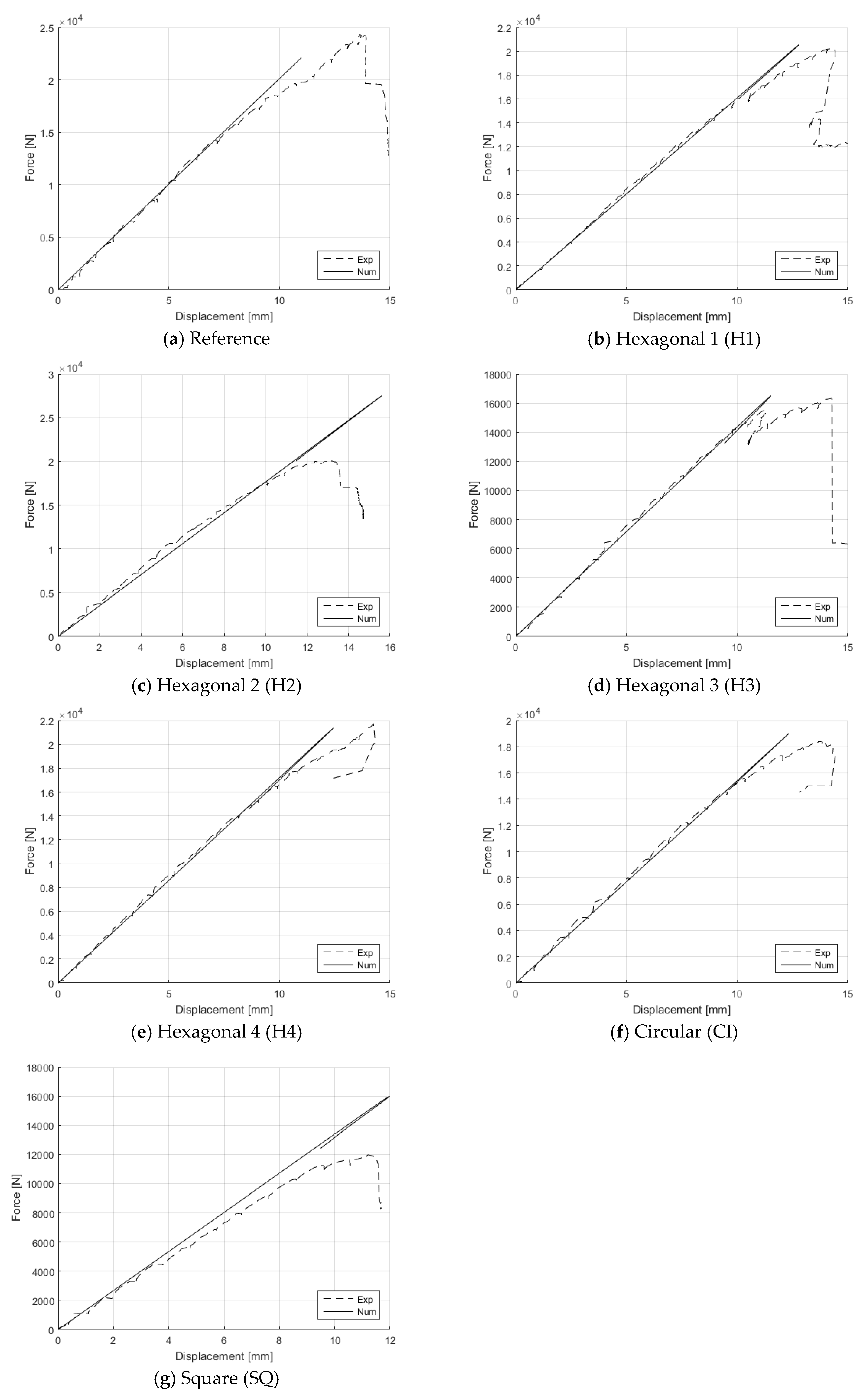
The load-displacement diagrams of the beam elements are presented in Figure 2. From Figure 2a,d, it can be concluded that the ultimate load of the beam elements decreases as larger cut-outs are introduced. Unfortunately, it is not possible to directly compare the ultimate loads of these beams since different failure modes were identified during loading. The reference beam element without cut-outs and the H2 element showed failure due to lateral torsional buckling, while beams H1 and H3 failed due to excessive cracking of the web. This shift in failure modes has also been recognised by other authors [2,6,9].
Furthermore, it can be seen from Figure 2b,e that the spacing of the cut-outs affects the ultimate load of the beam elements. The ultimate load of beam H4 is about 10% higher than that of H1. However, the initial cracking and start of the nonlinear phase in the load-displacement diagrams take place at roughly the same point, more specifically at a loading of about 18 kN and vertical displacement of 1 cm.
Lastly, it can also be seen from Figure 2f,g that the shape of the cut-out severely influences the ultimate strength of the I-joist. This is mainly due to the stress concentrations in the corners of the square-shaped cut-out. These stress concentrations will initiate the timber fracture more quickly and will therefore also lower the overall strength of the beam element.

3. Numerical Campaign

3.1. Numerical Model

Supplementary to the experimental campaign, finite element models are created to determine if the experimentally determined load-displacement diagrams can be realistically assessed by a numerical model. For the beams with cut-outs, nonlinear material behaviour of the fibreboard web is included in the numerical model according to a gradient enhanced damage model [11] in which a constant gradient parameter c = 100 mm² is used. Damage initiates after the first principal strain exceeds the damage threshold ft,web/Eweb = 0.0038 where the tensile strength and Young’s modulus of the web are, respectively, ft,web = 20 N/mm² and Eweb = 5300 N/mm². After damage initiation, an exponential damage evolution law is followed with a very high brittleness to simulate the brittle character of the fibreboard. The LVL flanges remain linear elastic (Young’s modulus Eflange = 13,000 N/mm² and Poisson’s ratio 0.2). Since the brittle material behaviour leads to a structural snap-back behavior, the force-displacement curve is traced using an energy release control algorithm [12].

3.2. Numerical Results

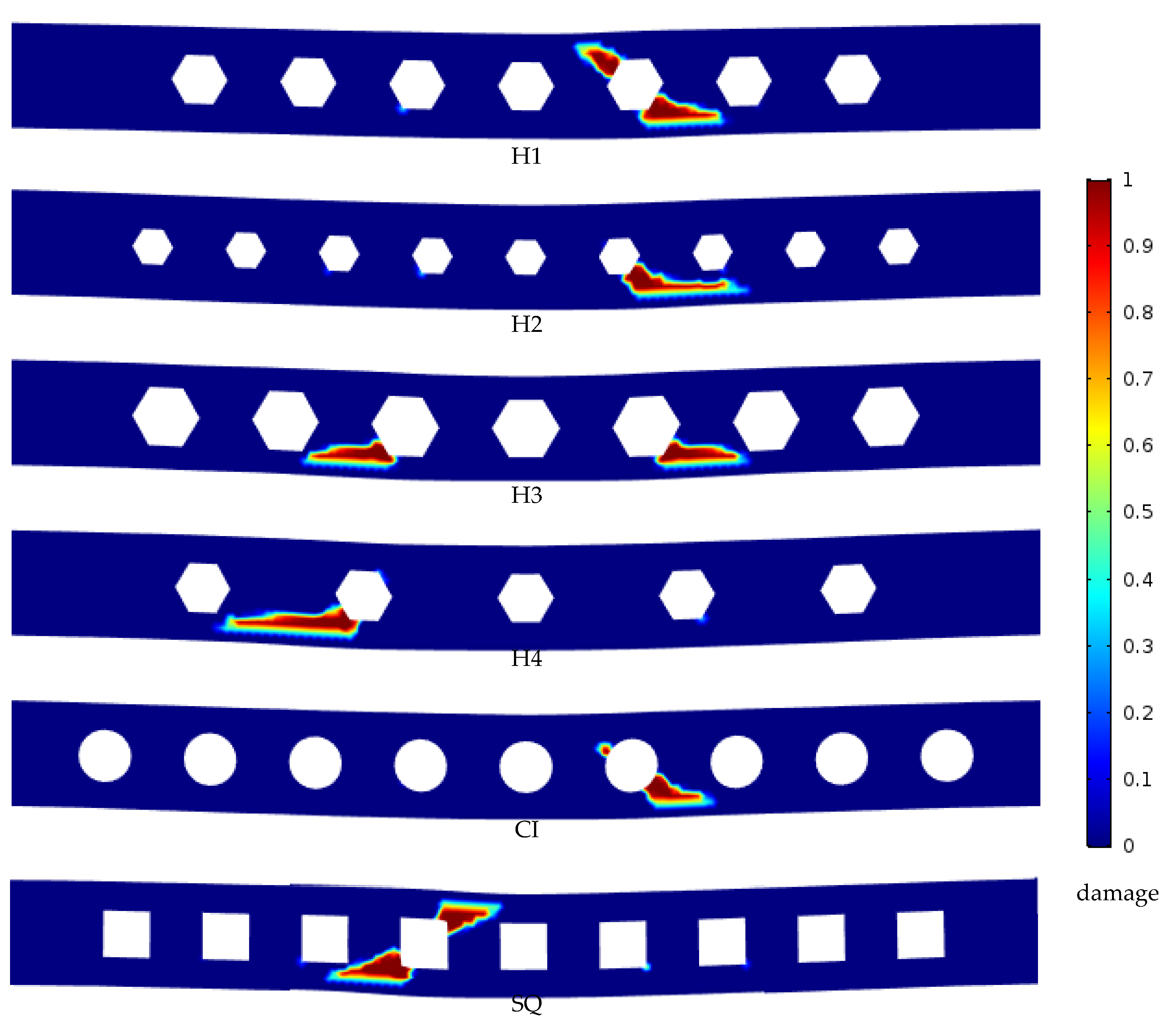
Overall, Figure 2 shows good agreement between the experimental and numerical data. Especially the initial stiffness and linear elastic behaviour of the beam elements is assessed well by the numerical model. The ultimate load is also in good agreement with the experimental value, except for the beams H2 and SQ, for which the numerical model overestimates the ultimate load (Figure 2c,g). For beam H2, this is associated with the failure mode which for this beam was due to lateral torsional buckling and not due to material failure of the hardboard web (geometric nonlinearities were not taken into account in the numerical model). Finally, Figure 3 depicts the failure mechanisms observed in the simulations, where it is noted that the asymmetric nature of these mechanisms (with the exception of beam H3) is caused by the asymmetric loading conditions of the beams: the exact, i.e., imperfect, roller positions of the experiments were also used in the simulations.

4. Conclusions

The impact of cut-outs on the mechanical behaviour of composite timber I-joists is investigated in a combined experimental and numerical study. The load-displacement diagrams of seven beams with different cut-out provisions are assessed experimentally and numerically using gradient enhanced finite element models. From the experimental tests, the influences on the ultimate load due to the cut-out size and shape is identified. Good agreement is reached between the experimental and numerical data for the elements for which the dominant failure mode is associated with material failure of the web.

Author Contributions

R.S. and B.V. conceived and designed the experiments; R.S. performed the experiments; R.S. and B.V. analysed the data; B.V. performed the numerical analyses; R.S. and B.V. wrote the paper.

Acknowledgments

This research was performed within the framework of the project SYNERGYTIMB, which is partially supported by Flanders Innovation & Entrepreneurship (VLAIO project number HBC.2016.0117).

Conflicts of Interest

The authors declare no conflict of interest. The founding sponsors had no role in the design of the study; in the collection, analyses, or interpretation of data; in the writing of the manuscript, and in the decision to publish the results.

References

  1. Leichti, R.J.; Falk, R.; Laufenberg, T.L. Prefabricated wood composite I-beams: A literature review. Wood Fiber Sci. 1990, 22, 62–79. [Google Scholar]
  2. Harte, A.M.; Baylor, G. Structural evaluation of castellated timber I-joists. Eng. Struct. 2011, 33, 3748–3754. [Google Scholar] [CrossRef]
  3. Polocoser, T.; Miller, T.H.; Gupta, R. Evaluation of Remediation Techniques for Circular Holes in the Webs of Wood I-joists. Masters Thesis, Oregon State University, Corvallis, OR, USA, 2012. [Google Scholar] [CrossRef]
  4. European Committee for Standardization. Eurocode 5: Design of Timber Structures—Part 1-1: Gereral—Common Rules and Rules for Buildings; European Committee for Standardization: Geneva, Switzerland, 2015. [Google Scholar]
  5. Kohnehpooshi, O.; Showkati, H. Numerical modeling and structural behavior of elastic castellated section. Eur. J. Sci. Res. 2009, 31, 306–318. [Google Scholar]
  6. Wang, S.; Cheng, J.J.R. Shear Behaviour of OSB Wood Composite I-Beams with Web Openings; Dept. of Civil Eng., Univ. of Alberta: Edmonton, AB, Canada, 1995. [Google Scholar]
  7. Zhu, E.C.; Guan, Z.; Pope, P.D.; Rodd, P.D. Finite element modelling of OSB webbed timber I-beams with interactions between openings. Adv. Eng. Softw. 2005, 36, 797–805. [Google Scholar] [CrossRef]
  8. Afzal, M.T.; Lai, S.; Chui, Y.H.; Pirzada, G. Experimental evaluation of wood I-joists with web holes. For. Prod. J. 2006, 56, 26–30. [Google Scholar]
  9. Morrissey, G.C.; Dinehart, D.W.; Dunn, W.G. Wood I-joists with excessive web openings: An experimental and analytical investigation. ASCE J. Struct. Eng. 2009, 135, 655–665. [Google Scholar] [CrossRef]
  10. Baylor, G.; Harte, A.M. Finite element modelling of castellated timber I-joists. Construct. Build. Mater. 2013, 47, 680–688. [Google Scholar] [CrossRef]
  11. Peerlings, R.H.; De Borst, R.; Brekelmans, W.A.; De Vree, J.H. Gradient enhanced damage for quasi brittle materials. Int. J. Numer. Meth. Eng. 1996, 39, 3391–3403. [Google Scholar] [CrossRef]
  12. Guttièrez, M.A. Energy release control for numerical simulations of failure in quasi-brittle solids. Commuun. Numer. Meth. Eng. 2004, 20, 19–29. [Google Scholar] [CrossRef]
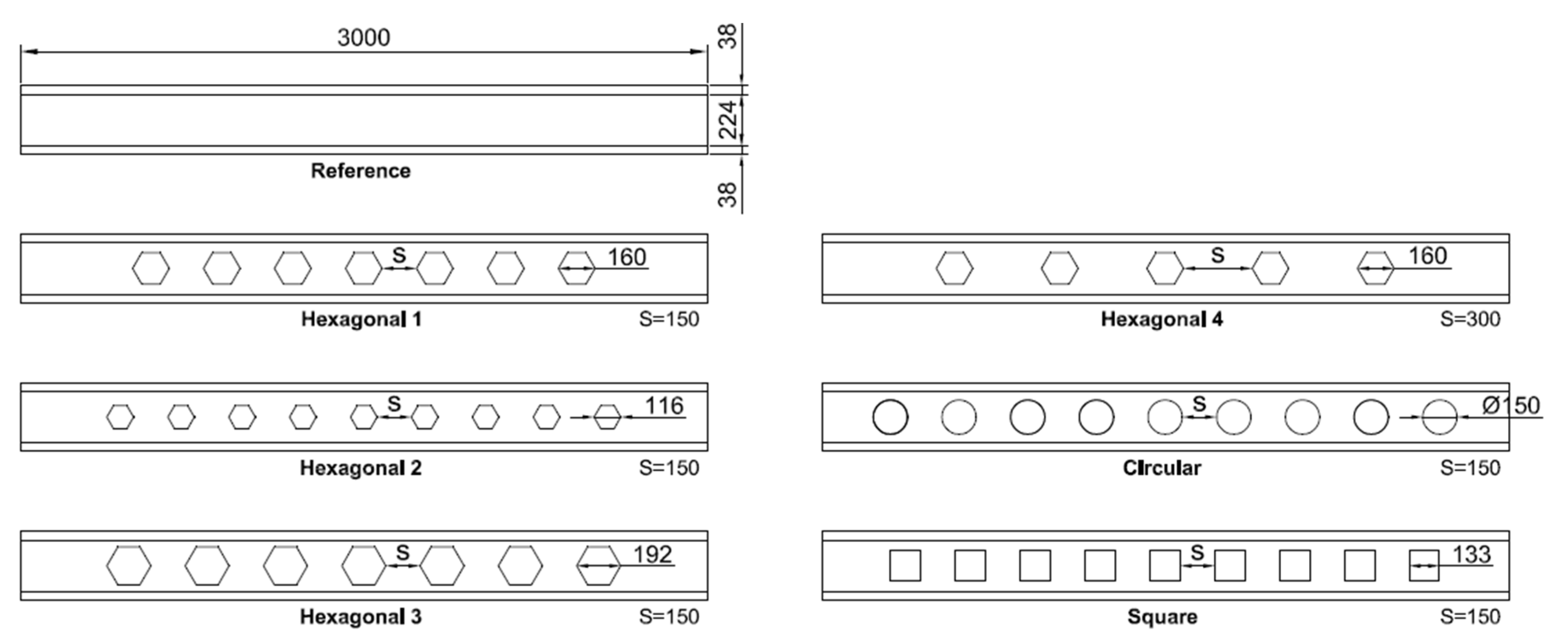
Figure 1. Overview of the geometries of the tested specimen, the applied cut-outs and spacing S.
Proceedings 02 00463 g001
Figure 2. Experimental and numerical load-displacement diagrams of the experimentally tested beam elements.
Proceedings 02 00463 g002
Figure 3. Numerical failure mechanisms of the beams.
Proceedings 02 00463 g003
Table 1. Overview of the geometric properties of the cut-outs for each associated beam element.
Beam ElementNumber of OpeningsSpacing [mm]Surface Area [mm²]
Hexagonal 1 (H1)715016,632
Hexagonal 2 (H2)91508691
Hexagonal 3 (H3)715024,142
Hexagonal 4 (H4)530016,632
Circular (CI)915017,689
Square (SQ)915017,689
Publisher’s Note: MDPI stays neutral with regard to jurisdictional claims in published maps and institutional affiliations.