Considerations of Failure Analysis in a Multi-Layered Composite Structure under Thermomechanical Loading †

Department of Non Destructive Testing and Physics, Vaal University of Technology, Vanderbijlpark 1900, South Africa
*
Author to whom correspondence should be addressed.
†
Presented at the 18th International Conference on Experimental Mechanics (ICEM18), Brussels, Belgium, 1–5 July 2018.
Proceedings 2018, 2(8), 447; https://doi.org/10.3390/ICEM18-05329
Published: 12 June 2018
(This article belongs to the Proceedings of The 18th International Conference on Experimental Mechanics)
Abstract
:The study seeks to investigate a failure of laminated composite structure subjected to a thermomechanical loading. Failure analysis of composite structures is an important design requirement. The stacking sequence of the structure investigated is restricted to ten thin layers. The fiber orientation, stacking sequence and material properties influence the response from the composite structure. Formulas are presented which are used to estimate the response of multi-layered composite structure to thermomechanical loads. A failure analysis is performed based on some known failure criteria. The values of the engineering properties for multi-layered composite structure and the results of the stress and strain distributions subjected to the forces and bending moments are presented. The numerical results were computed by using MATLAB script. Selected results of the numerical analysis have been presented.
1. Introduction
The composite materials are more important in internal combustion engines, machine components, thermal control and electronic packaging, automobile, train and aircraft structures [1]. They are also important for mechanical components such as brakes, pressure vessels, draft shafts, flywheels and tanks. Despite their significant advantages, composite materials suffer from different types of damage mechanism, such as fiber breakage, matrix crack, fiber matrix debonding, edge cracking and many more [2]. High performance-to-weight-ratio makes laminated composites contribute to a greater use in critical engineering structures which may be subjected to aggressive environments such as extreme temperatures [3,4]. A number of laminated composites consist of multi-directional layers of laminates to achieve certain mechanical properties and design requirements [3]. The laminates are formed by stacking two or more laminae with varying fiber orientations. This enables the structure to respond to complex states of stresses [5]. It is therefore crucial to have knowledge of the mechanical performance of these laminated composites when subjected to thermomechanical loading.
Quadratic failure theories such as Hoffman, Tsai-Wu and Tsai-Hill criteria are widely acknowledged for orthotropic materials [6]. For the purpose of this study, Tsai-Hill, Tsai-Wu and Hoffman theories are used for failure analysis in multi-layered graphite/epoxy structure exposed to thermomechanical loading. Interfiber failure or interfiber fracture (IFF) has been formulated depending on the Tsai-Wu and Chang-Chang failure theories. IFF analysis was considered in this study to account for delamination or matrix failure and also to predict the realistic behavior in graphite/epoxy material.
2. Mathematical Modeling
The approach used in this study relies on the classical lamination theory. It is therefore necessary to outline the elastic constants of a lamina and relate them to the engineering constants. The stress-strain relation of a composite lamina can be properly written in the matrix form defined in terms of Young’s modulus, shear modulus and Poisson’s ratio [7]
where are Young’s Moduli in directions 1 and 2; is the shear modulus in the 1-2 plane, are Poison’s ratios in the 1-2 and 2-1 planes. Thus, using the the lamina stress-strain relations can be given in a compact form as [6]
where is given in terms of stated in Equation (1) as follows
and . The laminate’s extensional stiffness, , coupling stiffness, and bending stiffness, are given respectively as follows [8]
where or . The forces per unit length, and and moments per unit length, and are considered. Using the forces per unit length and the moments per unit length, the vector of the mid-plane strains and the vector of mid-plane curvatures can be derived from the following equation [9].
with being the thermal load vector , is the thermal moment vector and is the inverse of . At this stage the stress-strain relation, accounting for mechanical and thermal effects can be outlined in the form [8]
where , , , gives the temperature change and are the thermal expansion coefficients given by [10]
and is the temperature distribution. The laminate constitutive equations are obtained by integrating Equation (6) over the thickness and used to obtain the mid-plane strains and mid-plane curvatures as follows:
where is the inverse of . The thermal stress and moment resultants on the right-hand side of Equation (8) can be stated in the form
and
respectively. The local stresses can be related to the global stresses by the following equation
3. Failure Analysis Criteria
3.1. Tsai-Hill Failure Criterion
Tsai-Hill equation for failure theory is stated in the form [11]
where and are .
If and , then the local stresses in Equation (11) can be written as , and . Applying the above to the Tsai-Hill failure theory the equation will possess only the global stress in the direction.
3.2. Tsai-Wu Failure Criterion
This failure criterion is based on total strain energy failure theory where failure is assumed to occur if the following condition is satisfied in the lamina [12];
where .
3.3. Hoffman Failure Criterion
Hoffman’s theory can be used for an orthotropic lamina with unequal tensile and compressive strengths where the equation is given by [13,14].
The equation for the interfiber failure can be derived as follows
The Tsai-Wu failure equation for the case of the interfiber failure/fracture where is given as
4. Numerical Experiment
An orthotropic graphite/epoxy lamina made up of ten layers is considered. The stacking sequence of the plies is [90;0;45;−45;90;90;−45;45;0;90]. The engineering constants and strength properties for this composite material are given in Table 1 below. The thickness of each ply is assumed to be 0.277 mm.
The orthotropic graphite/epoxy layer is assumed to be loaded by combined axial and shear stresses. Using the Tsai-Hill criterion, the strengths of the ply as a function of the fibre orientation is determined at r = 0.05.
5. Results and Discussion
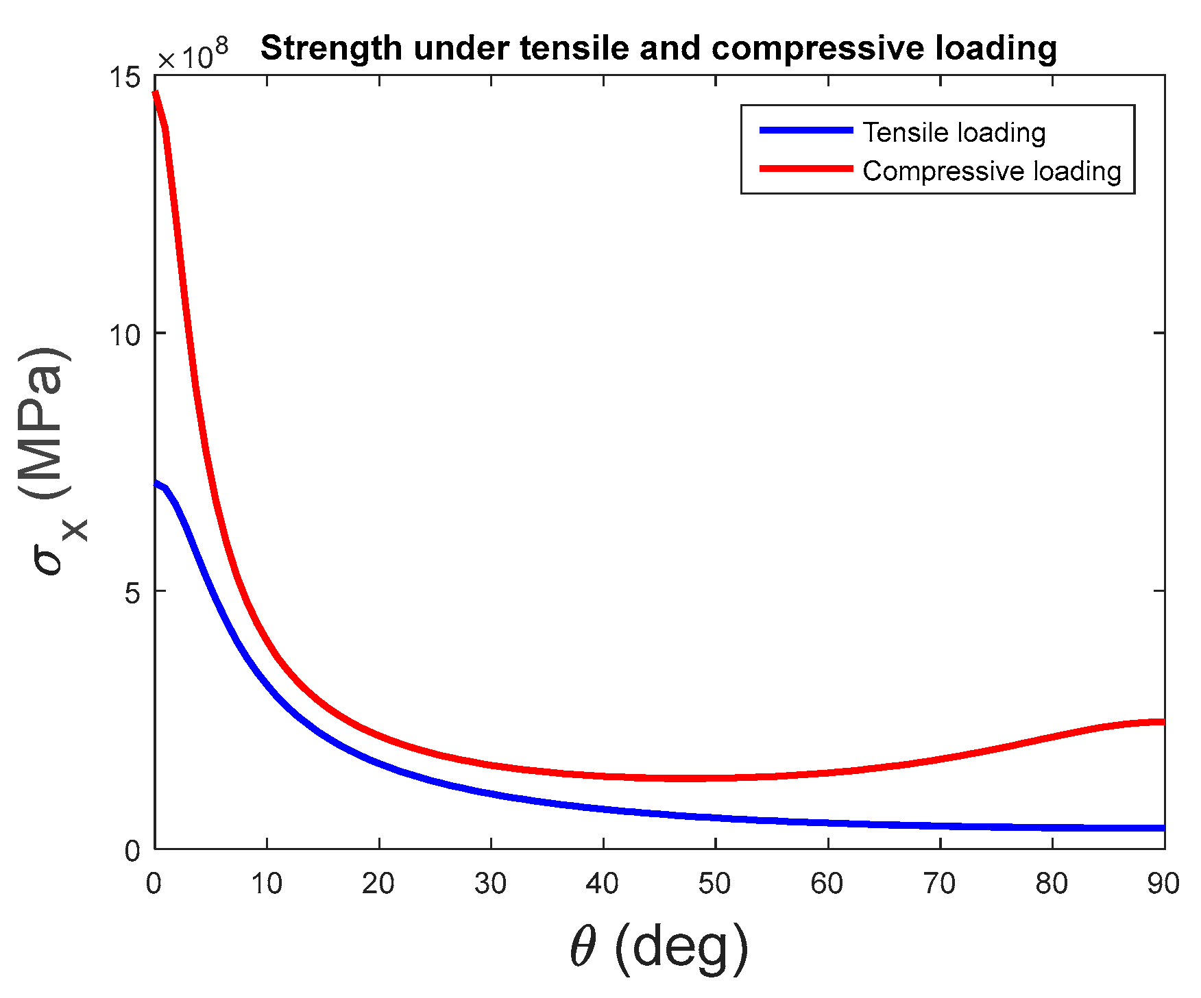
Figure 1 shows that at , Pa and Pa. The two values compare favourably with the health of the composite material since they are smaller than that of the ultimate strengths. However, when , the tensile and compressive loading are decreasing exponentially until at angle of 90°.
The results obtained after calculating for the Tsai-Hill, Tsai-Wu and Hoffmann failure criteria are shown in Table 2. Failure occurs when the set conditions are equal or greater than 1 for Tsai-Wu, Hoffman and Tsai-Hill failure criteria. From the results obtained, the structure will not fail according to Tsai-Wu and Hoffman as the values are less than 1. However, according to Tsai-Hill criterion, the graphite/epoxy structure will fail under the given strength and elastic properties.
Figure 2a shows that Tsai-Wu at has a maximum value of Pa at Pa For Chang-Chang at , the maximum value of Pa while that of Pa at .
For the Chang-Chang at and , the curves complement each other to form a curve similar to that of Tsai-Wu. The area outside the envelope indicates that interfibre failure occurs while the area inside the envelope indicates that interfibre failure does not occur. In Figure 2b, the value of Pa when and when Pa.
6. Conclusions
Failure analysis of multi-layered composite structure has been studied in the present work. The laminate considered for the present failure analysis is a ten-layered ply. The Tsai-Hill and Hoffmann failure criteria are in good agreement since the graphite/epoxy structure will not fail under the given set conditions. The results obtained indicate that the failure criteria used are good and can be used to predict interfiber failure in multi-layered composite structure.
References
- Zweben, C. Wiley Online Library (Composite Materials). Available online: http://onlinelibrary.wiley.com/doi/10.1002/9781118985960.meh110/pdf (accessed on 20 September 2016).
- Pawar, P.M.; Ganguli, R. On the effect of matrix cracks in composite Helicopter Rotor Blades. Compos. Sci. Technol. 2005, 65, 581–594. [Google Scholar] [CrossRef]
- Massabo, R.; Campi, F. Thermomechanical loading of laminates with imperfect interfaces. Procedia Eng. 2014, 88, 34–41. [Google Scholar] [CrossRef]
- Huang, Z.H. Modeling strength of multidirectional laminates under thermo-mechanical loads. J. Compos. Mater. 2011, 35, 281–304. [Google Scholar] [CrossRef]
- Dupir, I.; Țăranu, N.; Axinte, A. Effect of stacking sequence on the coefficients of mutual influence of composite laminates. IOP Conf. Ser. Mater. Sci. Eng. 2016, 161, 012052. [Google Scholar] [CrossRef]
- Greif, R.; Chapon, E. Investigation of successive failure modes in graphite/epoxy laminated composite beams. J. Reinf. Plast. Compos. 1993, 12, 602–603. [Google Scholar] [CrossRef]
- Yang, C.; Jiao, G.; Guo, H. Failure criteria for C/SiC composites under plane stress state. Theor. Appl. Mech. Lett. 2014, 4, 021007. [Google Scholar] [CrossRef]
- Uttam, S.; Koruche, S.F. Application of Classical Lamination Theory and Analytical Modeling of Laminates. Int. Res. J. Eng. Technol. 2015, 2, 958–965. [Google Scholar]
- Sundararaman, S.; Hu, J.; Chanrashekhara, K. Thermomechanical analysis of composite cylinders for hydrogen storage. In Proceedings of the SAMPE Conferene, Baltimore, MD, USA, 3–7 June 2007; pp. 1–12. [Google Scholar]
- Nettles, A.T. Basic Mechanics of Laminated Composite Plates; NASA: Huntsville, AL, USA, 1994. [Google Scholar]
- Engblom, J.J. Stress and Failure Analysis of Laminated Composite Structures; PDH Center: Faifax, VA, USA, 2012. [Google Scholar]
- Voyiadjis, G.Z.; Kattan, P.I. Mechanics of Composite Materials with MATLAB, 2005th ed.; Springer: Berlin, Germany, 2005; p. 189. [Google Scholar]
- Ryan, C. An Intelligible Software (CFA) Approach for Fiber-Reinforced Laminate Failure Analysis Including a Piecewise Representation of the Tsai-Wu Failure Criterion Using Excel and MatLab. Master’s Thesis, Master of Science, Schmidt Embry-Riddle Aeronautical University, Daytona Beach, FL, USA, 2009. [Google Scholar]
- Arafat, I.K. Progressive Failure Analysis of Laminated Composite Structures. Ph.D. Thesis, Doctor of Philosophy, Virginia Polytechnic Institute and State University, Blacksburg, VA, USA, 2015. [Google Scholar]
- Hallquist, J.O.; LS-Dyna, L.S. Theoretical Manual; Livermore Software Technology Corporation: Livermore, CA, USA, 2005. [Google Scholar]
- Chang, F.K.; Chang, K.Y. A progressive damage model for laminated composites containing stress concentration. J. Compos. Mater. 1987, 21, 834–855. [Google Scholar] [CrossRef]
Figure 1.
Comparison of tensile and compressive loading as the function of angle .

Figure 2.
Chang-Chang and Tsai-Wu interfibre fracture; (a) Comparing failure criteria for IFF when and . (b) IFF when .
Figure 2.
Chang-Chang and Tsai-Wu interfibre fracture; (a) Comparing failure criteria for IFF when and . (b) IFF when .


Table 1.
Table showing the stiffness and strength properties of a graphite/epoxy structure.
| Stiffness Properties | |||||||
| 0.28 | |||||||
| Strength Properties | |||||||
Table 2.
Results obtained from the Tsai-Hill, Tsai-Wu and Hoffmann failure theories.
| Tsai-Hill | Tsai-Wu | Hoffmann |
|---|---|---|
| −0.7441 |
Publisher’s Note: MDPI stays neutral with regard to jurisdictional claims in published maps and institutional affiliations. |
© 2018 by the authors. Licensee MDPI, Basel, Switzerland. This article is an open access article distributed under the terms and conditions of the Creative Commons Attribution (CC BY) license (https://creativecommons.org/licenses/by/4.0/).
Share and Cite
MDPI and ACS Style
Nyambeni, N.; Mabuza, B.R. Considerations of Failure Analysis in a Multi-Layered Composite Structure under Thermomechanical Loading. Proceedings 2018, 2, 447. https://doi.org/10.3390/ICEM18-05329
AMA Style
Nyambeni N, Mabuza BR. Considerations of Failure Analysis in a Multi-Layered Composite Structure under Thermomechanical Loading. Proceedings. 2018; 2(8):447. https://doi.org/10.3390/ICEM18-05329
Chicago/Turabian StyleNyambeni, Ngeletshedzo, and Boy Raymond Mabuza. 2018. "Considerations of Failure Analysis in a Multi-Layered Composite Structure under Thermomechanical Loading" Proceedings 2, no. 8: 447. https://doi.org/10.3390/ICEM18-05329