1. Introduction
Fiber-reinforced polymer (FRP) composite structures operating in open-air applications, such as wind turbine rotor blades, airplanes, and bridge decks, are subjected to different irregular loading profiles, in most cases including interrupted loading at high or low stress levels [
1].
The degradation of the cyclic-dependent mechanical properties of laminated composites occurs via several damage mechanisms, such as matrix cracking, debonding, delamination, transverse-ply cracking, and fiber failure, that are activated, either independently or synergistically, during fatigue loading [
2,
3]. In addition, due to the presence of the viscoelastic polymer matrix in a variety of laminated composites, the time-dependent mechanical properties of the material are also affected during cyclic loading, [
4]. The literature review showed that the effect of load interruption on the fatigue behavior of composite materials has not been extensively studied [
1,
5,
6]. Previous studies were based on very limited experimental programs, mainly investigating the interrupted fatigue behavior at only one stress level and without giving more information regarding the experimental conditions, and without providing any rational discussion regarding the interaction of the failure mechanisms and their influence on fatigue life
The objective of this work is to investigate the effect of loading interruption on fatigue behavior of ±45° angle-ply composite laminates.
2. Materials and Methods
Rectangular glass/epoxy [±45]
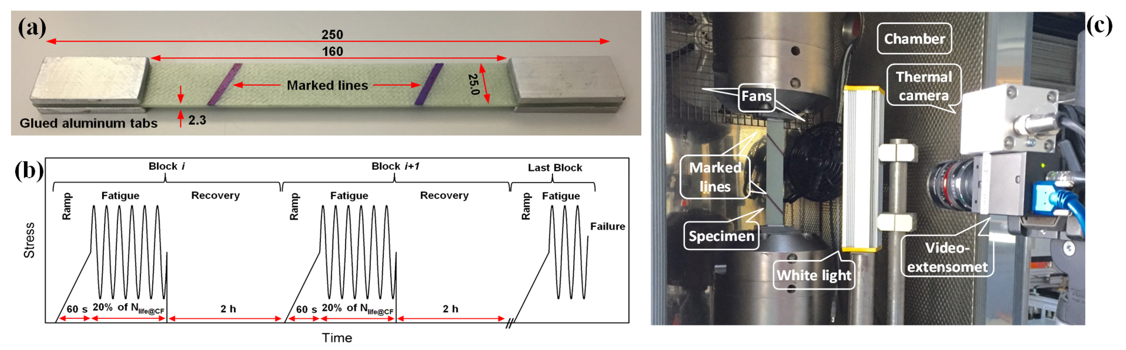
2s composite specimens with the average dimensions of 250 × 25 × 2.3 mm
3 (length × width × thickness) were prepared, according to ASTM D3039 as shown in
Figure 1a. Fatigue experiments were performed by applying two types of loading patterns. A continuous constant amplitude fatigue spectrum at different stress levels in order to derive baseline data in terms an S-N curve; and an second loading pattern during which the load was interrupted for two hours repetitively, after cycling for 20% of the fatigue life achieved under continuous loading at the same maximum cyclic stress level. A schematic representation of the interrupted loading program is shown in
Figure 1b. The duration of 20% of the fatigue life in each loading block was selected in order to obtain a significant number of interruptions in each fatigue experiment and a reasonable duration of the fatigue experiments. The transition from the mean fatigue loading to the zero-load intervals was achieved in one second.
The cyclic loading was performed in the range of maximum stress levels of 47 MPa–68 MPa in order to achieve lifetime between 10
3 and 10
6 cycles. The stress ratio,
R = σ
min/σ
max, was kept constant to 0.1 in order to apply tensile loads to the specimens. A loading rate of 30.5 kN/s was used for all tests. This loading rate was derived after preliminary experimental efforts in order to avoid self-generated temperature increases exceeding the glassy state during the fatigue loading [
7]. Different frequencies were thus selected in order to keep the loading rate constant for all stress levels. Four specimens were examined at each one of the six selected stress levels. All experiments were performed in an environmental chamber regulated at a constant temperature of 20 °C. Two fans were used to circulate the air inside the chamber and cool the specimen. The variation of the longitudinal strains was measured by a high-resolution video-extensometer with a frequency of acquisition of 160 images/s. An infrared (IR) thermal camera with an accuracy of 0.1 °C was also employed during the fatigue experiments to record the evolution of the specimen’s surface temperature. To detect the damage development in the translucent specimens at a macro-scale level, photographs were taken at regular intervals (depending on the life expectancy) with a digital camera. The experimental set-up is shown in
Figure 1c. After failure, the failure surfaces were examined using a digital handheld Dino-Lite microscope. The Ultraviolet Visible Near-Infrared (UV-Vis-NIR) spectroscopy technique was also used to measure the reflectance specimens. The reflectance of an undamaged specimen is caused by surface reflection and internal reflection due to the different reflectance indices of the matrix, fiber, and manufacturing imperfections, which cause the reflection at the boundary of two different media. Changes in the reflectance measurements for the same material indicate new interfaces in the path of the penetrated light that can be attributed to damage in the material volume [
8].
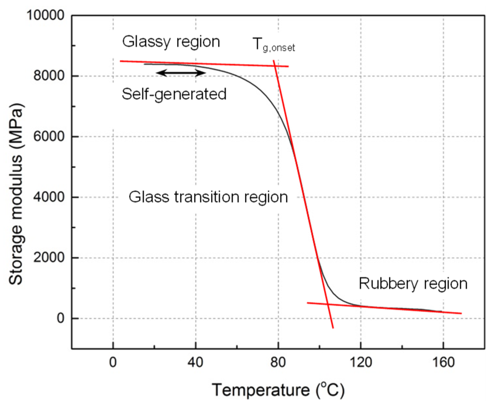
Dynamic Mechanical Analysis (DMA) was performed and shown in
Figure 2. It was observed that the storage modulus of the examined material was almost constant at temperatures lower than 45 °C.
3. Results and Discussion
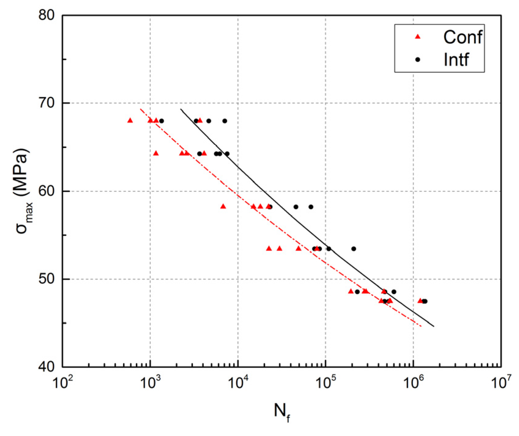
The fatigue behavior is shown in
Figure 3, where the maximum cyclic stress level,
σmax, is plotted versus the number of cycles to failure,
Nf. The specimens loaded under the interrupted fatigue pattern sustained significantly more cycles than those loaded continuously until failure. The effect was more pronounced at high stress levels, with average lifetime increases reaching 126% at the level of 68 MPa, while being much moderate at lower stress levels.
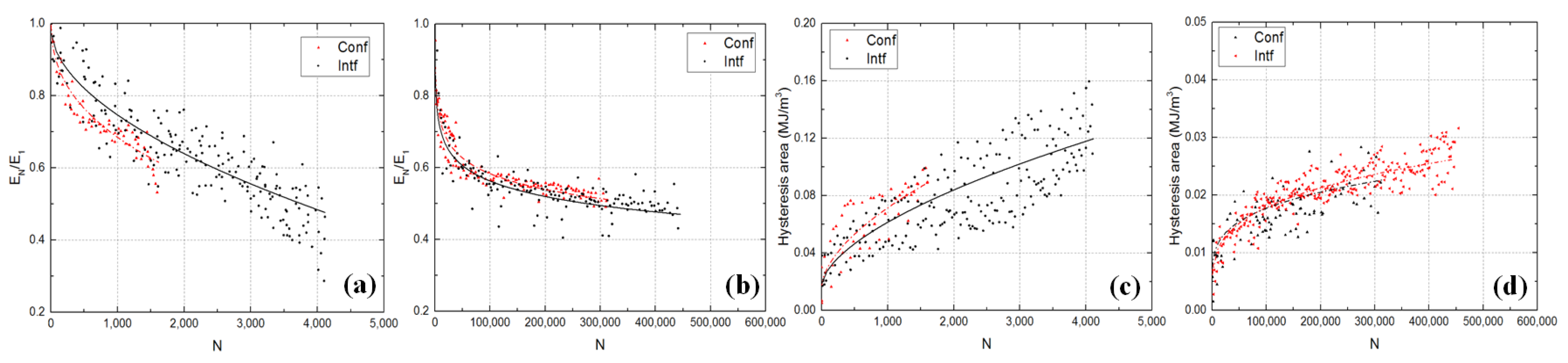
Figure 4a,b compares the fatigue stiffness degradation of specimens loaded under continuous and interrupted loading at high and low stress levels. A similar trend of stiffness degradation was observed at both stress levels as a result of damage formation and growth, i.e., an initial steep decrease during the first 10–15% of the lifetime followed by a steady state stiffness decrease up to specimen failure. At high stress level, by applying interrupted loading, the stiffness at failure decreased considerably more than in specimens subjected to continuous loading. This confirmed that the former specimens accumulated much more damage than the latter ones until failure. The rate of stiffness degradation was however lower under interrupted loading. At low stress levels, the stiffness difference and thus the effect of interruption almost disappeared.
The same comparison of the different loading patterns is shown for the evolution of the hysteresis loop areas in
Figure 4c for high and
Figure 4d for low stress levels. The hysteresis area (indicating energy dissipation) increased with the number of cycles at all stress levels. The values increased rapidly in the first loading block and then reached a steady state, which lasted for 80–90% of the fatigue life up to failure. Internal friction in damaged regions was the main cause of this energy dissipation [
9]. At high stress levels, much larger hysteresis loop areas before failure were observed for the specimens under interrupted loading, again indicating far greater energy dissipation and thus damage accumulation. The rate of damage accumulation was however lower under interrupted fatigue loading. At low stress levels, the differences again almost disappeared.
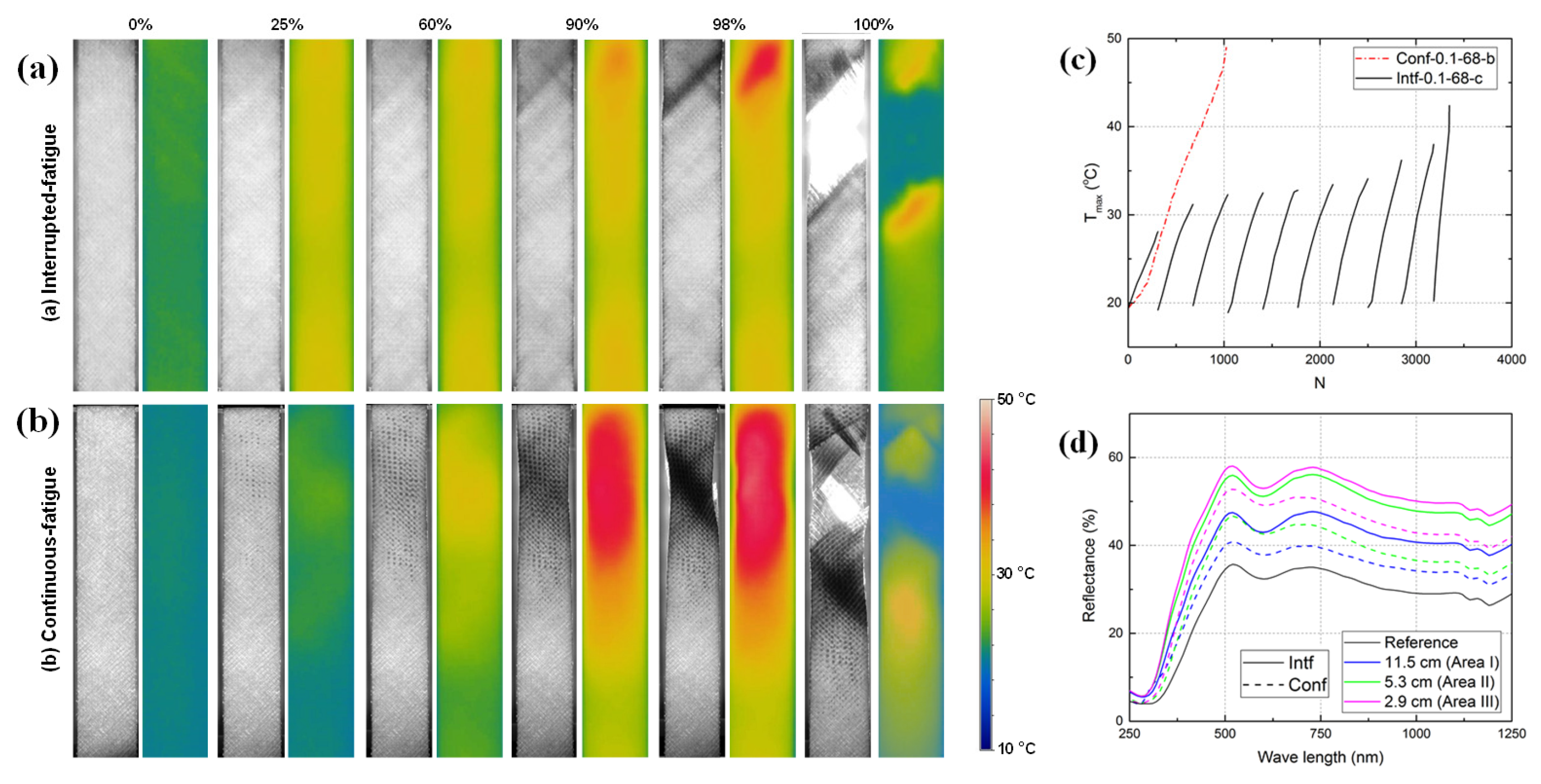
Figure 5a,b show the evolution of specimen translucency and the distribution of the self-generated temperature across the surface at different percentages of fatigue life for specimens loaded continuously and with interruptions at σ
max = 68 MPa. The creation of any form of cracks in the matrix and fiber matrix debonding, mainly when the crack surface was perpendicular to the beam of light, caused light scattering and changed the specimen translucency. Therefore, darker regions in the photos correspond to decreased light transmittance due to greater damage formation. As shown, for both cases with an increasing number of cycles, damage gradually appeared along the fibers, at around 45° with respect to the specimen longitudinal axis, which was thus attributed to matrix/fiber interface debonding. In addition, as thermal camera revealed, during the early stages of the fatigue life, a uniform distribution of surface temperature was observed, in both loading patterns. However, by increasing the number of cycles, the distribution of the temperature became more uneven, and hotspots, i.e., regions of high temperature concentrations, started appearing, which had an oval shape oriented in the fiber direction. These temperature increases were attributed to internal friction in damaged zones.
Comparison of the translucency and temperature distributions on the specimens’ surfaces in
Figure 5a,b revealed that damage was much more evenly distributed along the specimen under interrupted loading, while it was more concentrated, at the subsequent failure location, under continuous loading. This damage distribution throughout the whole specimen volume now explains why much more damage could be accumulated up to failure under interrupted loading, as described above. The effect of loading interruption on the damage distribution became negligible at low stress levels and it was more evenly distributed throughout the specimen volume.
Figure 5c shows the evolution of the maximum (hotspot) surface temperatures of selected specimens from each loading pattern. In continuous loading pattern, the maximum temperature showed an increasing trend while in interrupted loading pattern, the temperature dropped with load interruption and increased again when loading was restored in the next loading block. However, the rate of temperature rise increased with the number of loading blocks. Nevertheless, since temperatures remained clearly below the glass transition temperature in both cases, this effect was considered minor.
The reflectance results of the UV-Vis-NIR spectroscopy for the reference specimen are shown in
Figure 5d by the black solid line. In addition, measurements taken at different positions on the failed specimens at the same distance from the fracture surface are also presented in the same figure. The reflectance of the damaged specimen increased when the measurement was taken at regions closer to the failure location, indicating the accumulation of more damage in this region, with new interfaces and fatigue cracks. A comparison of the measured reflectance between specimens loaded interruptedly and continuously showed that by applying interrupted fatigue loading pattern the reflectance across the specimen length increased. Therefore, according to this technique and the assumption that increased reflectance can be interpreted as increased damage in the specimen volume, more damage was accumulated throughout the specimen, when loaded with interruptions. However, this method does not seem appropriate for capturing all the damage that has occurred; for example, small cracks across the beam of light may not reflect the light, particularly when they close after load removal.
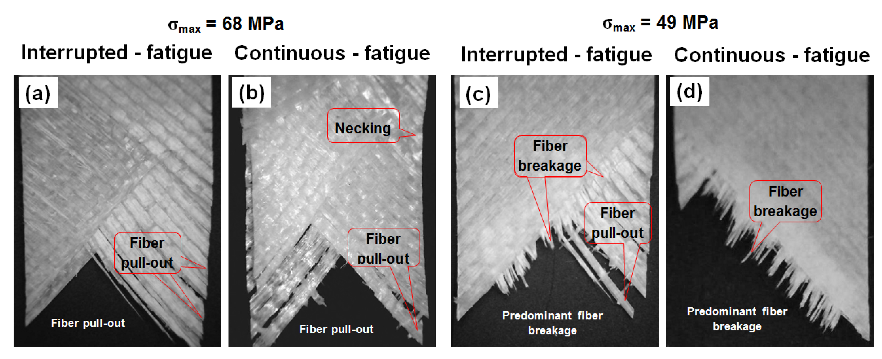
The fatigue fracture surfaces are shown in
Figure 6. For all cases, a diagonal damage pattern, following the 45° fiber direction, was observed. For higher stress levels in both loading patterns, the failure was characterized by extensive fiber pull-out, a consequence of the significant deterioration of the matrix/fiber interfaces, which hindered the transfer of the stresses from the matrix to the fibers at the concentrated damage zones. In addition, it was observed that the necking was more pronounced under continuous fatigue loading. At lower stress levels, a mixed-mode failure with fiber pull-out and fiber breakage was observed with predominant fiber breakage at the lowest stress level. The presence of fiber breakage at low stress levels was attributed to the more uniform and less severe damage distribution, which allowed the matrix and interface to transfer stresses to the fibers.
4. Conclusions
The tensile-tensile interrupted fatigue behavior of angle-ply, (±45)2s, glass/epoxy composite laminates has been experimentally investigated in this work. Different mechanical, thermal, and optical measurements were performed for the study of the specimens’ fatigue behavior at different stress levels and the following conclusions were drawn:
The specimens loaded under interrupted fatigue had longer fatigue lives than those continuously loaded at the same cyclic stress levels. This increase was more, and it was more considerable at higher stress levels.
By applying an interrupted fatigue loading pattern, the rate of stiffness degradation and energy dissipation per cycle decreased, while more uniform damage growth throughout the specimen volume was observed, which increased the specimen’s capacity to accumulate damage.
Under both loading patterns, failure was observed in the form of fiber pull-out; however, in specimens loaded continuously failure occurred with considerable necking. At low stress levels, failure with predominant fiber breakage under both loading patterns was observed


