Abstract
This paper presents an approach to model a ski jumper as a multi-body system for an optimal control application. The modeling is based on the constrained Newton-Euler-Equations. Within this paper the complete multi-body modeling methodology as well as the musculoskeletal modeling is considered. For the musculoskeletal modeling and its incorporation in the optimization model, we choose a nonlinear dynamic inversion control approach. This approach uses the muscle models as nonlinear reference models and links them to the ski jumper movement by a control law. This strategy yields a linearized input-output behavior, which makes the optimal control problem easier to solve. The resulting model of the ski jumper can then be used for trajectory optimization whose results are compared to literature jumps. Ultimately, this enables the jumper to get a very detailed feedback of the flight. To achieve the maximal jump length, exact positioning of his body with respect to the air can be displayed.
1. Introduction
Within this paper, the development of a multi-body simulation model (MBS) [1] for the optimal control (OC) of a ski jumper is presented. This model features a nonlinear dynamic inversion (NDI) feedforward-feedback controller approach [2] with nonlinear reference models to control the bodies [3]. Basically, the NDI approach will provide an interface between the reference models for the movement that are based on the muscle dynamics of each body and the overall dynamics of the MBS. This structure has the benefit of providing both the capability to model the complex interaction between the muscle movement and the movement of the bodies, while it also retains a simple representation for the OC as the NDI controller circuit linearizes the behavior from the muscle movement to the body movement.
Current models of ski jumpers are mainly based on simple representations given by a point-mass or a rigid-body: The first model was invented by Straumann [4] and features a simple symmetric point-mass approach to get an insight into the dynamics of the jump and its influence parameters. Study [5] provides a symmetric rigid-body model for the trajectory optimization of a ski jumper considering the maximal jump length with wind. A four-link model of a ski jumper is developed in [6] and was compared to experimental data. Finally, the study in [7] provides a large scale MBS of the in-run and take-off for a ski jumper.
This paper illustrates the development of a MBS for the flight phase of a ski jumper suitable for OC. We develop the model as a MBS since only by this we can show an influence characterization and give valuable insights for the athletes in a sophisticated way. Therefore, we combine a model of the movement kinematics of a ski jumper with the muscle activation dynamics by a NDI controller approach. This framework represents the jumper’s movement, while maintaining a structure that is easy to solve for the OC task. This OC tasks will be carried out by the MATLAB-based toolbox FALCON.m [8].
2. Multi-Body Model
Using the Principle of Jourdain [1] and the coupled equations of motion (EoM) of a rigid-body [2], we get the following systems of equations, which represents the MBS:
The symbols are defined as: the unity matrix, is the mass of the body (frame and origin for each body ), the moment of inertia matrix, the mass matrix, the linear, and the rotational acceleration. The forces are , the moments , the rotational velocity with its skew-symmetric matrix , and the linear velocity is . and are the jacobians for translation and rotation respectively. The body index is with being the maximal number of bodies in the system.
Using a dependence between the generalized and physical coordinates, , and velocities, , we end with a coupled systems of ordinary differential EoM [1]:
It should be noted that the body properties, e.g., inertia or mass, are dependent on the human body model introduced in [9]. The aerodynamics are based on the models provided in [10,11].
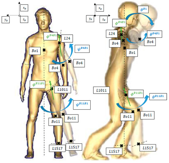
Equation (2) is used to set up the EoM. Figure 1 gives an example for a set of four bodies (torso, leg, arm, and ski) and their movement as a symmetric MBS. This model is used for the OC with the following generalized coordinates and velocities:

Figure 1.
MBS model of ski jumper with several bodies and movement directions.
Here, are the relative orientation angles (roll, pitch, yaw) between the bodies. The local earth frame is fixed on the take-off table (the x-axis points in hill direction, while the z-axis points up). The distances to the table are given by and with their velocities and respectively. The derivative of the first body angle is the pitch rate , while the other body angles are directly differentated with respect to time.
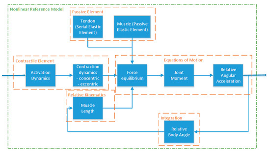
The muscles are modeled using a Hill-type model [12], including tendon, elastic, and contractile element [13,14,15]. Figure 2 illustrates the workflow of the nonlinear reference model, including the muscle model that commands the NDI controller of Section 3.

Figure 2.
Subsystems and interactions between parts of nonlinear reference model based on Hill-type muscle model.
3. Nonlinear Dynamic Inversion
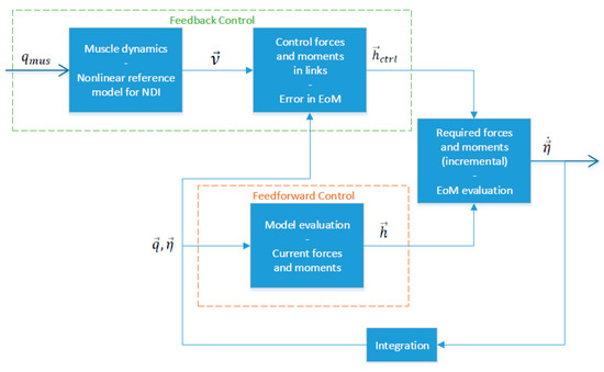
NDI is a well-established theory in aircraft control: Its main feature is the provision of a nonlinear control law that renders linear behavior between input and output of the system [2]. The usage of the NDI strategy in OC applications has recently been proven to be successful in order to make the solution of large systems more efficient [16]. Generally, NDI introduces a pseudo-control that the dynamic model must follow. In our approach, the pseudo-control will be the acceleration of the relative angles, e.g., , between the body parts, whose movements will be shaped by the muscle models of Section 2. Note that we will use a feedforward-feedback NDI in this work, which is illustrated in Figure 3. Within the feedforward control (dashed, orange box), we evaluate the model at the current state to calculate the left- and right-hand side of the EoM and use this to incorporate all the current physical movement capabilities within the model. By this, the controller is relieved of heavy duty as the ski jumper is an underactuated system and therefore, couplings are imminent. The feedback part solves the EoM at the current pseudo control for all controllable elements of the dynamics (ctrl):

Figure 3.
Structure of feedforward-feedback NDI control approach with nonlinear reference model for the MBS ski jumper OC model.
If we are already achieving the desired trajectory, the control deficiency is zero. The control deficiency is added to the right-hand side, when solving the EoM in the last step of Figure 3. This leads to a feasible trajectory and achieves the desired trajectory:
Here, the zero vector is of appropriate size for the non-controllable states and symbolizes the underactuation of the system. Note that inserting the calculation of the control deficiency (Equation (3)) in the augmented EoM (Equation (4)) directly yields the desired linear decoupling property of the NDI for the controllable states. Further on, we augment our pseudo control with standard PD error controllers to account for disturbances and model uncertainties [2,16]. The proportional gain is chosen to be , while the derivative gain is .
4. Optimal Control
In general, the model developed in Section 2 and Section 3 is used to solve the following OC problem:
In Equation (5), the cost functional is depicted by , including Mayer term and Lagrange term , the equality constraints are while the inequality constraints are . Additionally, the optimized trajectory must fulfill the state dynamics , which are represented by the MBS EoM in this work (Section 2.1). These are depending on the states (containing and ) and controls (containing the muscle activations ). The symbols and are the initial and final time respectively.
We model the EoM within the FALCON.m framework [8] and use a direct collocation method to transcribe the problem into a NLP [17]. This problem will then be solved using the NLP solver IPOpt [18] with tolerances of . We examine a cost functional that is trying to achieve a maximal flight length, while also trying to minimize the control effort. This minimal control effort symbolizes the jumper’s desire to fly as calm as possible to achieve a high judge score. The number of collocation points is linearly spaced and 101. The following initial condition that corresponds to the beginning of the flight phase at Okurayama hill in Sapporo is used [5] ():
5. Illustrative Example
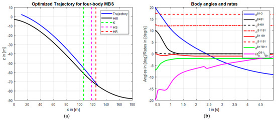
Figure 4 depicts an illustrative example for the OC results of the developed MBS (jumper mass: ; jumper height: ). In Figure 4a the optimized trajectory (solid blue) on Okurayama hill is shown. The dashed lines symbolize the length of K-point (K), hill size (HS), and hill record (HR) respectively. We can see that the optimized trajectory is slightly further than the hill record. This shows the capabilities of OC. Part (b) of the figure illustrates the time development of the body angles and the upper body rate. These angles are similar to the results published in [5], which confirms the validity of the developed model. From Figure 4b we see that the upper body angle (solid blue) decreases over time by the angular rate (solid magenta) such that the jumper in the end is almost parallel to the jumping hill. During this period the jumper decreases the arm angle such that the arms are parallel to the upper body. This increases his surface area and therefore the lift. He also closes the gap to the skis (solid green), while the ski opening angle (dashed-dotted red) remains almost constant.

Figure 4.
Optimized trajectory (a) and body angles and upper body rate over the flight time (b) for four-body MBS on Okurayama hill.
6. Conclusions and Perspective
This paper proposed a multi-body modeling technique for the OC of a ski jumper. The technique is based on the formulation of the MBS of a ski jumper by the constrained Newton-Euler-Equations. The model was combined with a NDI approach that linked the nonlinear muscle reference models with the dynamic movement of the ski jumper. The nonlinear muscle models provided a physical trajectory that the dynamic ski jumper followed due to the NDI control law. The OC was conducted using the Matlab-based toolbox FALCON.m. The setup allowed an easy solution of the OC problem, because the NDI decoupled the dynamics. Additionally, it provided a meaningful trajectory. The results showed that a MBS model is superior to the standard point-mass or rigid-body models, which are normally used for OC, as we gain a more detailed insight into the jumper’s movement.
Further research is directed into the development of a more sophisticated multi-body model: Here, at first the influence of a different number of bodies should be considered and the most realistic combination for the ski jumper should be described. Additionally, a system identification, for the aerodynamics and body properties, must be conducted to enhance the performance of the multi-body model. With this enhanced model, the conduction of a sensitivity analysis should be considered to get an even more detailed characterization of the influences.
Supplementary Materials
FALCON.m is available from www.falcon-m.com.
Acknowledgments
This research was supported by the Deutsche Forschungsgemeinschaft (DFG) through the TUM International Graduate School of Science and Engineering (IGSSE).
Conflicts of Interest
The authors declare no conflict of interest.
References
- Leitner, R.; Koppitz, P. Quick Modeling of Fixed- and Rotary-Wing Aircrafts using a synthetic tree structured Multibody Approach. In Proceedings of the AIAA Modeling and Simulation Technologies Conference, Minneapolis, MN, USA, 13–16 August 2012. [Google Scholar]
- Stevens, B.L.; Lewis, F.L. Aircraft Control and Simulation, 2nd ed.; Wiley: Hoboken, NJ, USA, 2003. [Google Scholar]
- Peter, F.; Leitao, M.; Holzapfel, F. Adaptive Augmentation of a New Baseline Control Architecture for Tail-Controlled Missiles Using a Nonlinear Reference Model. In Proceedings of the AIAA Guidance, Navigation and Control Conference, Minneapolis, MN, USA, 13–16 August 2012. [Google Scholar]
- Straumann, R. Vom Ski-Weitsprung und seiner Mechanik. Ski: Jahrbuch des Schweizerischen Ski-Verbandes = Annuaire de l’Association Suisse des Clubs de Ski; Volume 21, p. 1926.
- Seo, K.; Murakami, M.; Yoshida, K. Optimal flight technique for V-style ski jumping. Sports Eng. 2004, 7, 97–103. [Google Scholar] [CrossRef]
- Hubbard, M.; Hibbard, R.L.; Yeadon, M.R.; Komor, A. A multisegment dynamic model of ski jumping. J. Appl. Biomech. 1989, 5, 258–274. [Google Scholar] [CrossRef][Green Version]
- Hermsdorf, H.; Hildebrand, F.; Hofmann, N.; Müller, S. JUMPICUS—Computer Simulation in Ski Jumping (P95). In The Engineering of Sport 7; Estivalet, M., Brisson, P., Eds.; Springer: Paris, Germany, 2008; Volume 1, pp. 491–497. [Google Scholar]
- Rieck, M.; Bittner, M.; Grüter, B.; Diepolder, J. Fast and Free Optimal Control for MATLAB®. Available online: http://www.fsd.mw.tum.de/software/falcon-m/ (accessed on 22 May 2016).
- De Leva, P. Adjustments to Zatsiorsky-Seluyanov’s segment inertia parameters. J. Biomech. 1996, 29, 1223–1230. [Google Scholar] [CrossRef]
- Meile, W.; Reisenberger, E.; Mayer, M.; Schmolzer, B.; Muller, W.; Brenn, G. Aerodynamics of ski jumping: Experiments and CFD simulations. Exp. Fluids 2006, 41, 949–964. [Google Scholar] [CrossRef]
- Seo, K.; Watanabe, I.; Murakami, M. Aerodynamic force data for a V-style ski jumping flight. Sports Eng. 2004, 7, 31–39. [Google Scholar] [CrossRef]
- Hill, A.V. The Heat of Shortening and the Dynamic Constants of Muscle. Proc. R. Soc. Lond. B Biol. Sci. 1938, 126, 136–195. [Google Scholar]
- Günther, M. Computersimulationen zur Synthetisierung des Muskulär Erzeugten Menschlichen Gehens Unter Verwendung Eines Biomechanischen Mehrkörpermodells. Dissertation, Eberhard-Karls-Universität, 1997. [Google Scholar]
- Van Soest, A.J.; Bobbert, M.F. The contribution of muscle properties in the control of explosive movements. Biol. Cybern. 1993, 69, 195–204. [Google Scholar] [CrossRef] [PubMed]
- Gordon, A.M.; Huxley, A.F.; Julian, F.J. The variation in isometric tension with sarcomere length in vertebrate muscle fibres. J. Physiol. 1966, 184, 170–192. [Google Scholar] [CrossRef] [PubMed]
- Diepolder, J.; Bittner, M.; Piprek, P.; Grüter, B.; Holzapfel, F. Facilitating aircraft optimal control based on numerical nonlinear dynamic inversion. In Proceedings of the 2017 25th Mediterranean Conference on Control and Automation (MED), Valletta, Malta, 3–6 July 2017; pp. 141–146. [Google Scholar]
- Betts, J.T. Practical Methods for Optimal Control and Estimation Using Nonlinear Programming, 2nd ed.; Society for Industrial and Applied Mathematics: Philadelphia, PA, USA, 2010. [Google Scholar]
- Wächter, A.; Biegler, L.T. On the implementation of an interior-point filter line-search algorithm for large-scale nonlinear programming. Math. Program. 2006, 106, 25–57. [Google Scholar] [CrossRef]
Publisher’s Note: MDPI stays neutral with regard to jurisdictional claims in published maps and institutional affiliations. |
© 2018 by the authors. Licensee MDPI, Basel, Switzerland. This article is an open access article distributed under the terms and conditions of the Creative Commons Attribution (CC BY) license (https://creativecommons.org/licenses/by/4.0/).