Development of a Simulation Model for Swimming with Diving Fins †

1
Department of Systems and Control Engineering, Tokyo Institute of Technology, Tokyo 152-8552, Japan
2
Department of Mechanical Sciences and Engineering, Tokyo Institute of Technology, Tokyo 152-8552, Japan
3
Development Department, Tabata Co., Ltd., Tokyo 340-0813, Japan
*
Author to whom correspondence should be addressed.
†
Presented at the 12th Conference of the International Sports Engineering Association, Brisbane, Queensland, Australia, 26–29 March 2018.
Proceedings 2018, 2(6), 288; https://doi.org/10.3390/proceedings2060288
Published: 12 February 2018
(This article belongs to the Proceedings of The 12th Conference of the International Sports Engineering Association)
Abstract
:The simulation model to assess the performance of diving fin was developed by extending the swimming human simulation model SWUM. A diving fin was modeled as a series of five rigid plates and connected to the human model by springs and dampers. These plates were connected to each other by virtual springs and dampers, and fin’s bending property was represented by springs and dampers as well. An actual diver’s swimming motion with fins was acquired by a motion capture experiment. In order to determine the bending property of the fin, two bending tests on land were conducted. In addition, an experiment was conducted in order to determine the fluid force coefficients in the fluid force model for the fin. Finally, using all measured and identified information, a simulation, in which the experimental situation was reproduced, was carried out. It was confirmed that the diver in the simulation propelled forward in the water successfully.
1. Introduction
Scuba diving is becoming popular as a leisure activity. Although manufacturers produce various types of diving fin, these developments are based on qualitative methods because of the difficulty in estimating the fin efficiency quantitatively. In order to assess the performance of diving fins quantitatively, an experimental method was proposed [1]. However, it is difficult to establish an experimental method which can assess the diving fins quantitatively, since experimental methods using actual divers are affected by unexpected variations of human motion. As an alternative approach, computer simulation is considered to be promising. Indeed, the simulation model for the monofin swimming has been already developed [2] by extending the swimming human simulation model SWUM [3]. The objective of this study was to develop the simulation model to assess the performance of diving fin by extending the swimming human simulation model SWUM. If such simulation model is established, it will be a useful tool for the assessment of not only diving fins but also diving motions [4].
2. Methods
2.1. Construction of the Simulation Model
The simulation model in the present study was constructed by extending the swimming human simulation model SWUM [3]. SWUM was designed to solve the six degrees-of-freedom absolute movement of the whole swimmer’s body as a single rigid body by time integration using the inputs of the swimmer’s body geometry and relative joint motion. The swimmer’s body is represented by a series of 21 rigid body segments as follows: lower and upper waist, lower and upper chest, shoulders, neck, head, upper and lower hips, thighs, shanks, feet, upper arms, forearms and hands. Each body segment is represented by a truncated elliptic cone. The unsteady fluid force and gravitational force are taken into account as external forces acting on the whole body. The unsteady fluid force is assumed to be the sum of the inertial force due to the added mass of the fluid, normal and tangential drag forces and buoyancy. These components are assumed to be computable, without solving the flow, from the local position, velocity, acceleration, direction, angular velocity, and angular acceleration for each part of the human body at each time step. The coefficients in this fluid force model were identified using the results of an experiment with a limb model and measurements of the drag acting on swimmers taking a glide position in the previous studies [3]. As a result of the identification, the fluid force model was found to have satisfactory performance. Many other studies by SWUM, including its validation and application, have been already conducted to date [5,6,7,8,9,10].
In the present study, a diving fin blade was modeled as a series of five rigid plates and connected to the human model by springs and dampers, as shown in Figure 1a. These plates were connected to each other by virtual springs and dampers [8], and fin’s bending property was represented by rotational springs as well [2], as shown in Figure 1b.
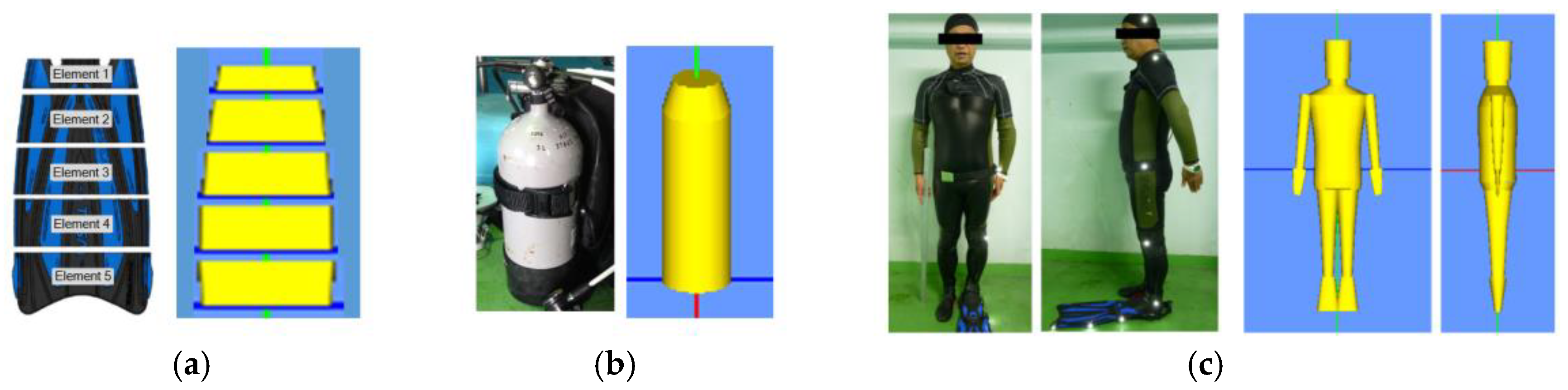
The diving fin targeted in the present study was SF-22, Tabata Co., Ltd. (Tokyo, Japan). The shape of the fin model was determined based on the actual dimensions of that fin, as shown in Figure 2a. The thickness of the fin model was determined from the mass of the actual fin, assuming that the density of the fin was equal to that of the surrounding water. The shape of the tank model was determined based on the dimensions of the actual tank, as shown in Figure 2b. For the diver model, photographs of one male experienced diver with a diving suit were taken, as shown in Figure 2c. The shape of the diver model was determined from the photographed images.
2.2. Acquistion of input Data for the Model
2.2.1. Swimming Motion of the Diver
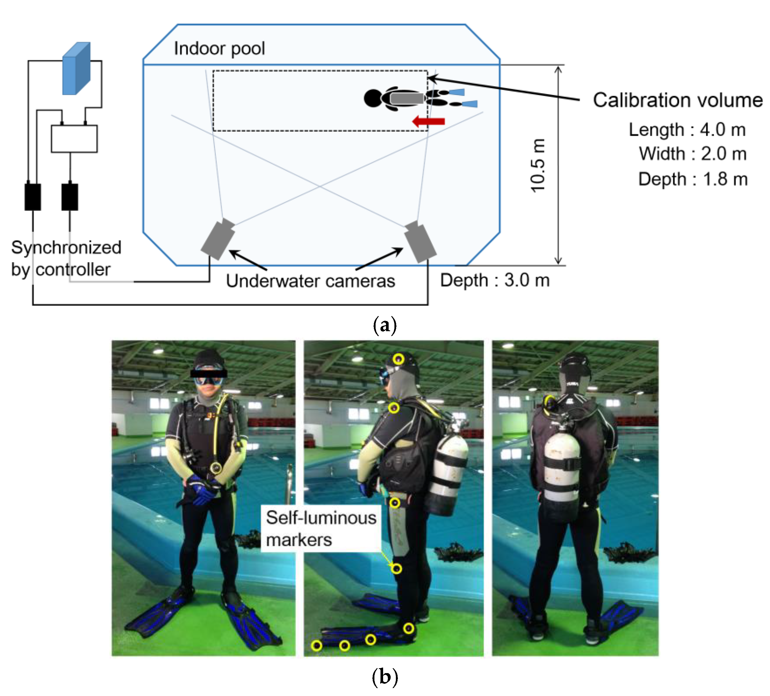
The swimming motion of the diver with fins was acquired by a motion capture experiment. The experimental setup is schematically shown in Figure 3a. In this experiment, the male experienced diver, who was photographed to determine the shape of the diver model, swam in an indoor pool horizontally at a constant depth and at a constant speed. Eight self-luminous markers were attached to the left side of the diver and the fin, as shown in Figure 3b. The swimming motion of the diver was filmed by two underwater cameras. Two sample images filmed by the cameras are shown in Figure 4. By using filmed images, three-dimensional coordinates of the markers and the resultant joint angles of the diver were calculated.
2.2.2. Bending Property of the Fin
In order to identify the bending property of the fin, two bending tests were conducted. One test was stationary and the other was dynamic. In the stationary test, a weight was added to the tip of the fin so that the fin could bend overall, as shown in Figure 5a. The displacements of six markers (No. 0~6) were measured by a scale. The spring constants of the rotational springs as bending stiffness in the simulation were determined so that the displacements of the markers in the simulation reproducing the experimental situation were sufficiently consistent with those in the experiment. An example of the results in the experiment and simulation is shown in Figure 5b. It can be seen that the experimental and simulated displacements were consistent with each other. Next, in the dynamic test, the weight at the tip of the fin was suddenly detached and the unsteady displacements of the markers were filmed by a camera. The damping coefficients of the rotational dampers in the simulation were determined so that the displacement behaviors of the markers in the reproducing simulation became close to the measured ones in the experiment.
2.2.3. Fluid Force Coefficients of the Fin
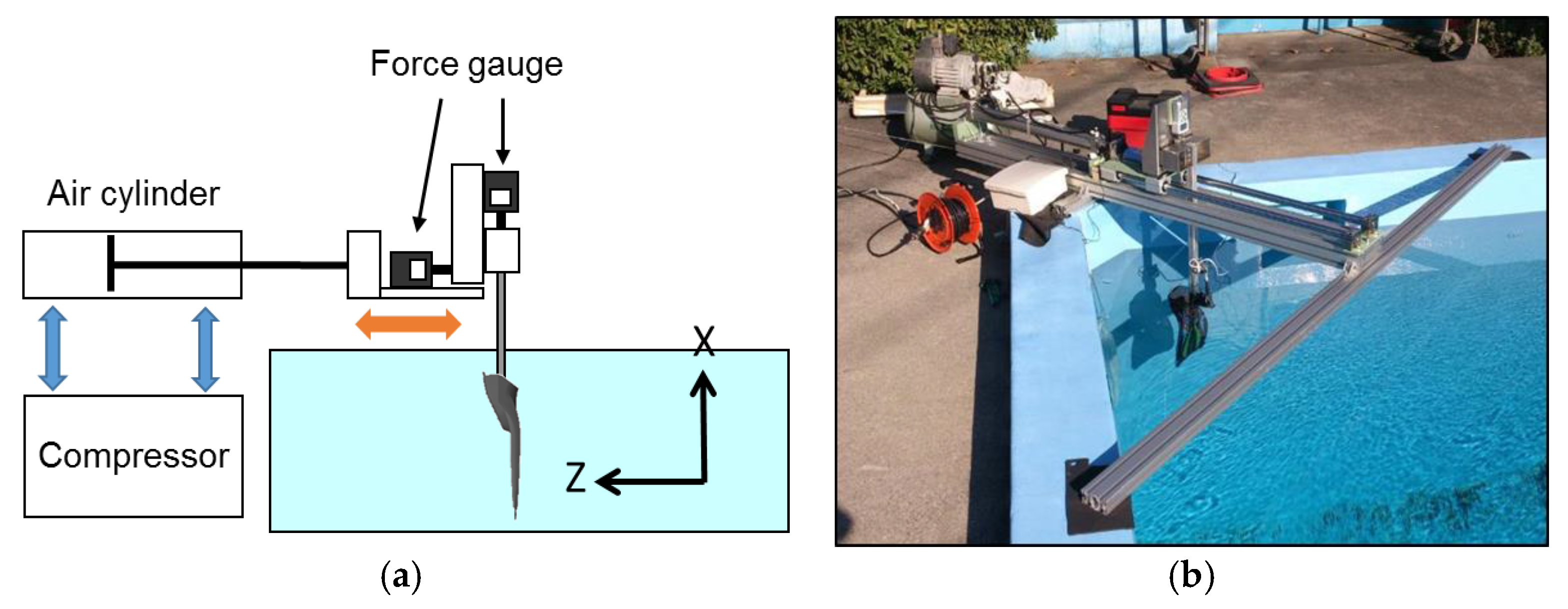
In order to determine the fluid force coefficients in the simulation, an experiment, in which the fin was moved in a water tank, was conducted. The schematic figure and photograph of the experimental setup are shown in Figure 6. The fin was moved in the horizontal direction by an air cylinder and a compressor. The horizontal and vertical forces acting on the fin were measured by two force gauges. This experimental situation was reproduced in the simulation as well. Two kinds of fluid force coefficients, the coefficient for the inertial force due to added mass of fluid and the coefficient for normal drag force, were adjusted and finally determined so that the resultant forces acting on the fin in the simulation became close to the measured ones in the experiment. The results are shown in Figure 7. Although some discrepancies were seen especially regarding the phase, the measured curves were considered to be reproduced in the simulation.
2.2.4. Fluid Force Coefficients of the Diver
In the SWUM formulation, the drag force which acts on the swimmer’s body is basically represented by the ‘tangential drag force’ in the fluid force model. Although the coefficient for the tangential drag force was determined in the previous study [3], this value was for a swimmer with a competitive swimwear. In the present study, a diver put on additional diving equipment, such as buoyancy control jacket, regulator set, wetsuit and mask. Therefore, the fluid force coefficient for the tangential drag force of the diver was determined so that the average swimming speed in the simulation reproducing the propulsion of the diver was consistent with the measured one.
3. Results and Discussion
Using all the input data acquired in the previous section, the simulation reproducing the propulsion of the diver was carried out. Kicking cycle was 1.65 s in this case. Three kicking cycles were computed in the simulation. The initial swimming speed was set to 0 m/s. The animation images of the swimming motion in the simulation is shown in Figure 8. It was found that the diver in the simulation successfully propel forward by the propulsive force produced by the fins. It was also found that the fins successfully bent during kicking. The swimming velocity in the simulation is shown Figure 9. The average swimming speed of the third cycle was 0.51 m/s. The peak-to-peak fluctuation during the third cycle was 0.091 m/s. This was 17.8% of the average swimming speed. The same quantity was calculated for the experiment and was found to be 17.8% as well. Therefore, it was suggested that the present simulation model can predict not only the bending movement of the fins but also the unsteady velocity fluctuation of the diver.
4. Conclusions
The simulation model for swimming with diving fins were developed in the present study. The input data for the simulation were acquired by various experiments. The results of simulation suggested that the model was promising to become a tool for assessment of diving fins as well as diving motions.
Conflicts of Interest
The authors declare no conflict of interest.
References
- Minak, G. Evaluation of the performance of free-diving fins. Sports Eng. 2004, 7, 153–158. [Google Scholar] [CrossRef]
- Nakashima, M.; Suzuki, S.; Nakajima, K. Development of a simulation model for monofin swimming. J. Biomech. Sci. Eng. 2010, 5, 408–420. [Google Scholar] [CrossRef]
- Nakashima, M.; Satou, K.; Miura, Y. Development of swimming human simulation model considering rigid body dynamics and unsteady fluid force for whole body. J. Fluid Sci. Technol. 2007, 2, 56–67. [Google Scholar] [CrossRef]
- Zamparo, P.; Pendergast, D.R.; Termin, B.; Minetti, A.E. How fins affect the economy and efficiency of human swimming. J. Exp. Biol. 2002, 205, 2665–2676. [Google Scholar] [CrossRef] [PubMed]
- Nakashima, M. Mechanical study of standard six beat front crawl swimming by using swimming human simulation model. J. Fluid Sci. Technol. 2007, 2, 290–301. [Google Scholar] [CrossRef]
- Nakashima, M. Simulation analysis of the effect of trunk undulation on swimming performance in underwater dolphin kick of human. J. Biomech. Sci. Eng. 2009, 4, 94–104. [Google Scholar] [CrossRef]
- Kiuchi, H.; Nakashima, M.; Cheng, K.B.; Hubbard, M. Modeling fluid forces in the dive start of competitive swimming. J. Biomech. Sci. Eng. 2010, 5, 314–328. [Google Scholar] [CrossRef]
- Nakashima, M.; Kiuchi, H.; Nakajima, K. Multi agent/object simulation in human swimming. J. Biomech. Sci. Eng. 2010, 5, 380–387. [Google Scholar] [CrossRef]
- Nakashima, M. Modeling and simulation of human swimming. J. Aero Aqua Bio-Mech. 2010, 1, 11–17. [Google Scholar] [CrossRef]
- Nakashima, M.; Suzuki, S.; Ono, A.; Nakamura, T. Development of the transfemoral prosthesis for swimming focused on ankle joint motion. J. Biomech. Sci. Eng. 2013, 8, 79–93. [Google Scholar] [CrossRef]
Figure 1.
Schematic figure of the simulation model for swimming with diving fins: (a) Overall view; (b) Detailed representation of the fin part.
Figure 1.
Schematic figure of the simulation model for swimming with diving fins: (a) Overall view; (b) Detailed representation of the fin part.
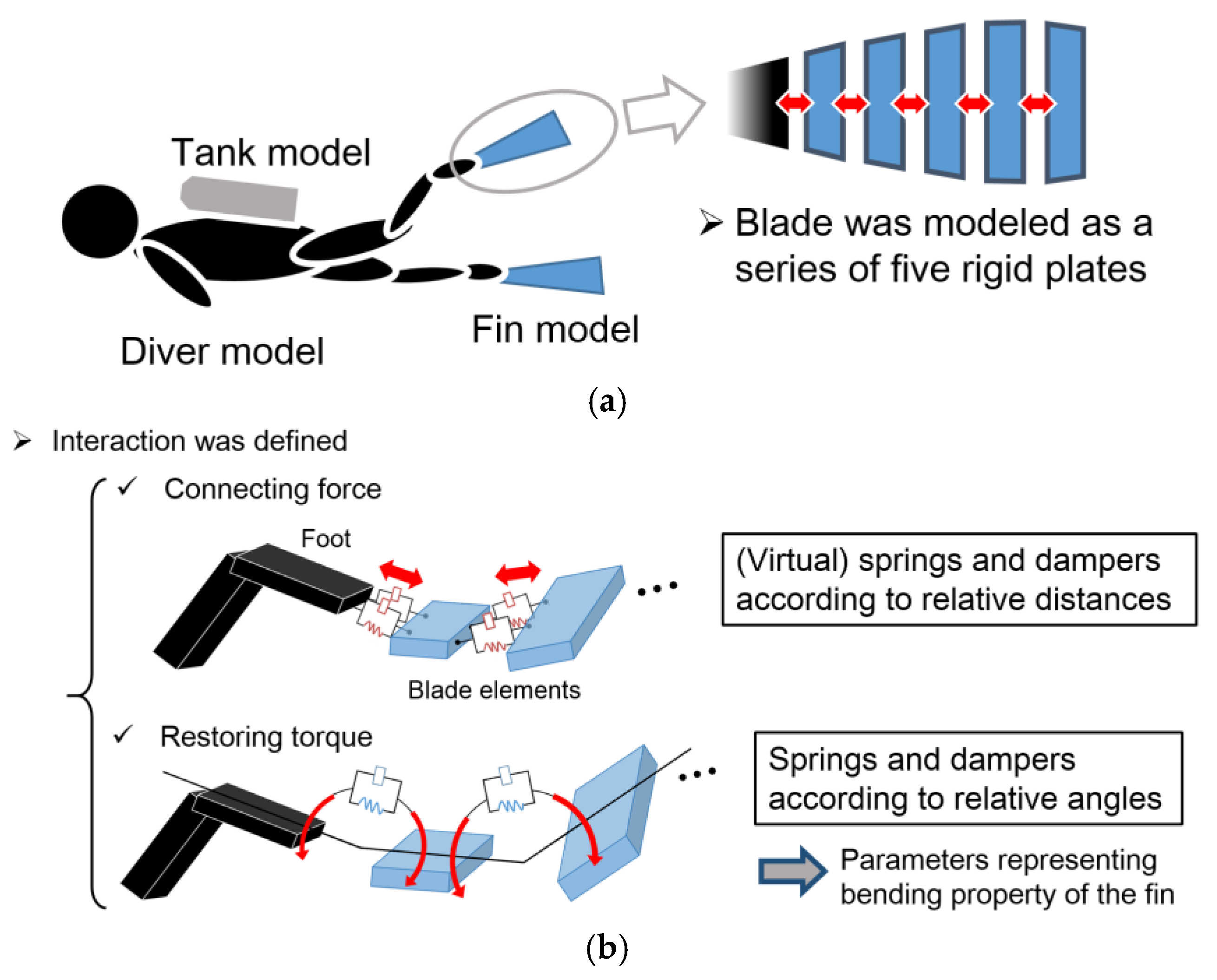
Figure 2.
The shapes of the simulation model. In each figure, the left side is the photographed image and the right side is the model: (a) Fin model; (b) Tank model; (c) Diver model.
Figure 2.
The shapes of the simulation model. In each figure, the left side is the photographed image and the right side is the model: (a) Fin model; (b) Tank model; (c) Diver model.

Figure 3.
Schematic figure of the experimental setup and photographs of the diver: (a) Experimental setup; (b) Photographs of the diver.
Figure 3.
Schematic figure of the experimental setup and photographs of the diver: (a) Experimental setup; (b) Photographs of the diver.

Figure 4.
Images filmed by the two underwater cameras.
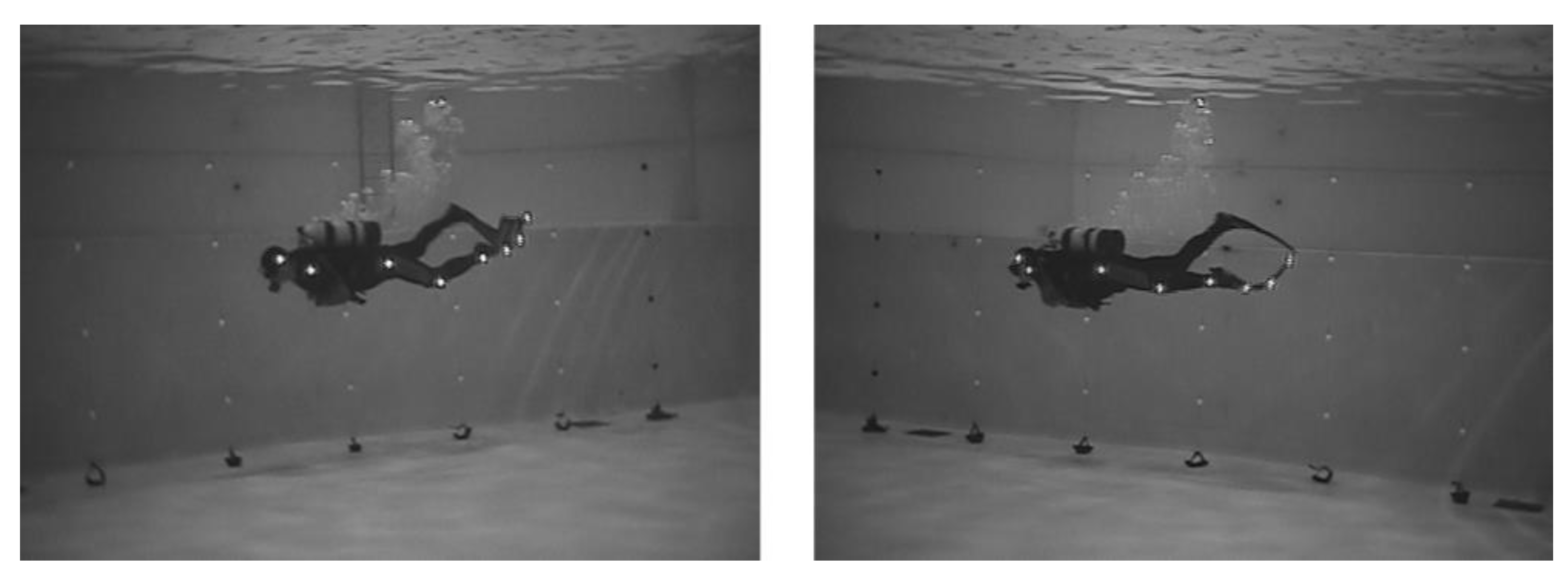
Figure 5.
Stationary test to determine the bending stiffness of the fin: (a) Experimental setup; (b) An example of the results for the experimental and simulated displacements. The weight was 3 kg in this case.
Figure 5.
Stationary test to determine the bending stiffness of the fin: (a) Experimental setup; (b) An example of the results for the experimental and simulated displacements. The weight was 3 kg in this case.
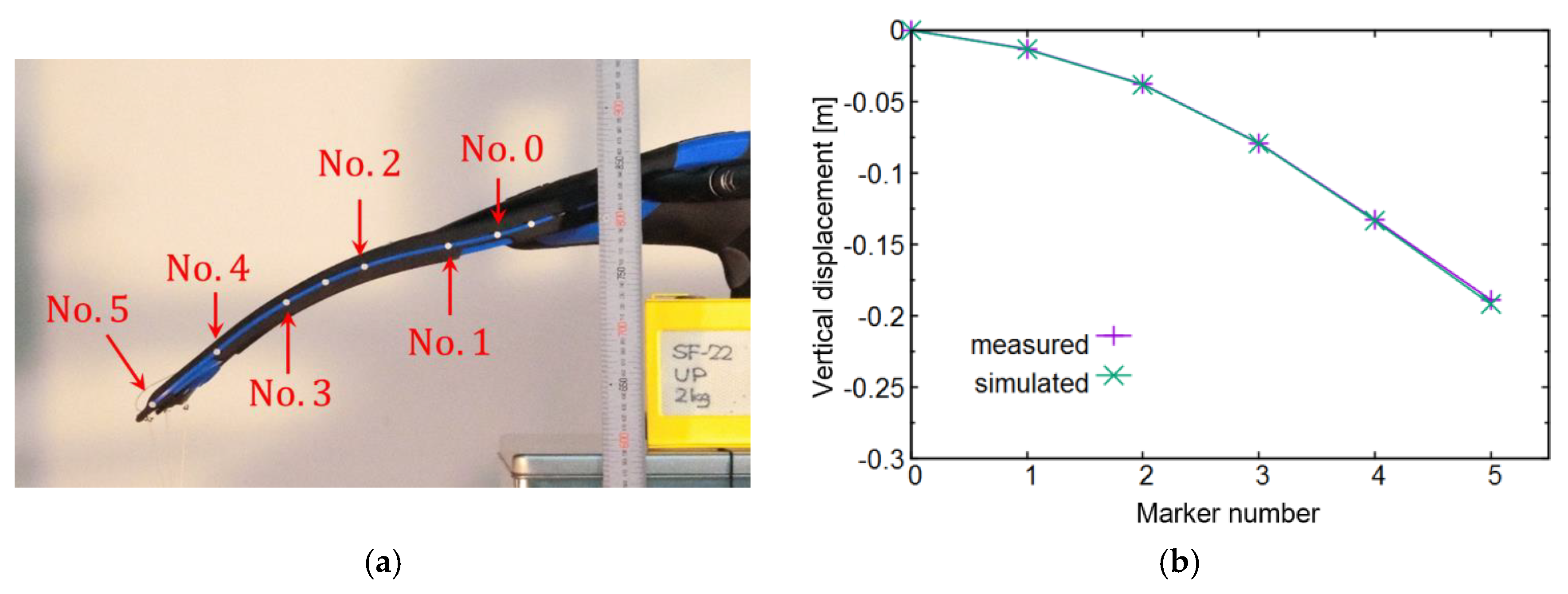
Figure 6.
Experimental setup in order to determine the fluid force coefficients of the fin: (a) Schematic figure; (b) Photograph.
Figure 6.
Experimental setup in order to determine the fluid force coefficients of the fin: (a) Schematic figure; (b) Photograph.

Figure 7.
The measured and simulated forces acting on the fin: (a) Horizontal force when the fin moved in +Z direction; (b) Vertical force when the fin moved +Z direction; (c) Horizontal force when the fin moved in −Z direction; (d) Vertical force when the fin moved in −Z direction.
Figure 7.
The measured and simulated forces acting on the fin: (a) Horizontal force when the fin moved in +Z direction; (b) Vertical force when the fin moved +Z direction; (c) Horizontal force when the fin moved in −Z direction; (d) Vertical force when the fin moved in −Z direction.

Figure 8.
Animation images of the swimming motion in the simulation. Kicking cycle was 1.65 s in this case: (a) Time t = 0.00 s; (b) t = 0.21 s; (c) t = 0.42 s; (d) t = 0.63 s; (e) t = 0.84 s; (f) t = 1.06 s; (g) t = 1.27 s; (h) t = 1.48 s.
Figure 8.
Animation images of the swimming motion in the simulation. Kicking cycle was 1.65 s in this case: (a) Time t = 0.00 s; (b) t = 0.21 s; (c) t = 0.42 s; (d) t = 0.63 s; (e) t = 0.84 s; (f) t = 1.06 s; (g) t = 1.27 s; (h) t = 1.48 s.
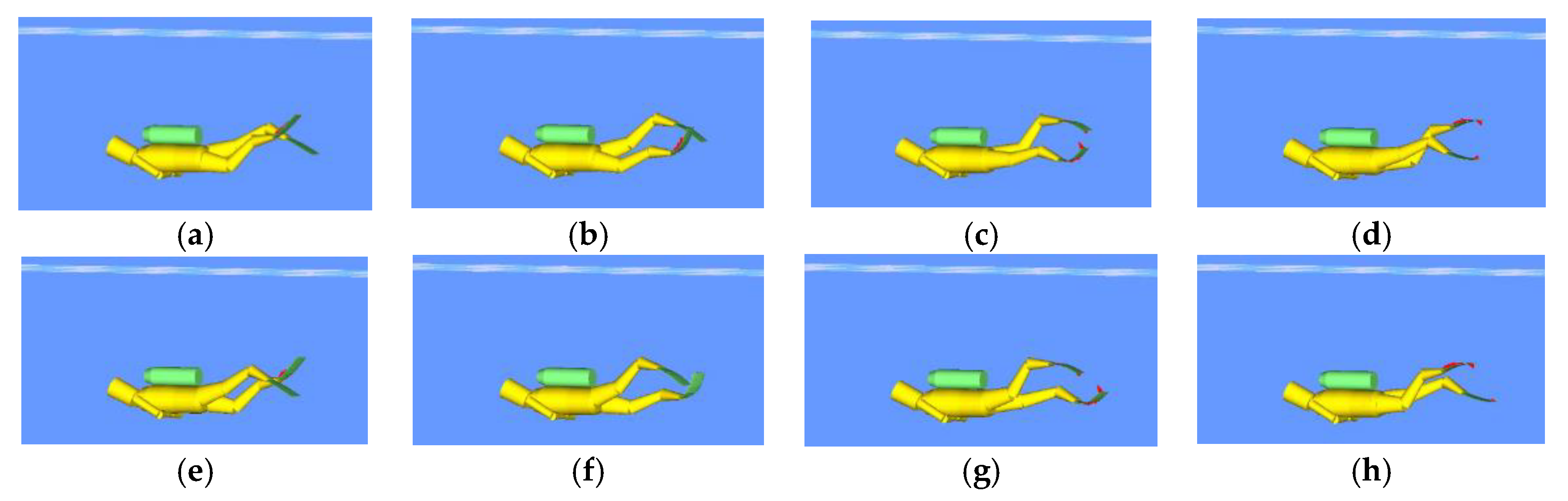
Figure 9.
Result of swimming velocity in the simulation. The average swimming speed of the third cycle was 0.51 m/s. The peak-to-peak fluctuation during the third cycle was 0.091 m/s (17.8% of the average swimming speed).
Figure 9.
Result of swimming velocity in the simulation. The average swimming speed of the third cycle was 0.51 m/s. The peak-to-peak fluctuation during the third cycle was 0.091 m/s (17.8% of the average swimming speed).

Publisher’s Note: MDPI stays neutral with regard to jurisdictional claims in published maps and institutional affiliations. |
© 2018 by the authors. Licensee MDPI, Basel, Switzerland. This article is an open access article distributed under the terms and conditions of the Creative Commons Attribution (CC BY) license (https://creativecommons.org/licenses/by/4.0/).
Share and Cite
MDPI and ACS Style
Nakashima, M.; Tanno, Y.; Fujimoto, T.; Masutani, Y. Development of a Simulation Model for Swimming with Diving Fins. Proceedings 2018, 2, 288. https://doi.org/10.3390/proceedings2060288
AMA Style
Nakashima M, Tanno Y, Fujimoto T, Masutani Y. Development of a Simulation Model for Swimming with Diving Fins. Proceedings. 2018; 2(6):288. https://doi.org/10.3390/proceedings2060288
Chicago/Turabian StyleNakashima, Motomu, Yosuke Tanno, Takashi Fujimoto, and Yutaka Masutani. 2018. "Development of a Simulation Model for Swimming with Diving Fins" Proceedings 2, no. 6: 288. https://doi.org/10.3390/proceedings2060288