Abstract
The forgiveness of golf putters is traditionally achieved through weight distribution. Higher MOI (moment of inertia) putters will show less ball speed loss on impacts away from the sweet spot. A very large MOI putter, however, may not be desired by a golfer due to weight or appearance. The relationship between ball speed and impact location is affected by the mass properties of the putter (i.e., CG location, mass, moments of inertia, products of inertia) and the putter face. It has been shown that certain face properties, such as milling patterns, grooves, or soft inserts, can have small effects on ball speed. This paper proposes a method to normalize the ball speed on laterally miss-hit putter impacts using a “model-specific” milling pattern of variable depth and pitch, resulting in the largest possible region of the face providing consistent putt distances, thus improving performance given the average player’s impact pattern.
1. Introduction
Golf putters, like drivers and irons, are designed with strong consideration for forgiveness. Amateur golfers tend to impact the putter face over a relatively large area, increasing the need for performance on poor strikes. For a golfer of handicap 18 and greater, this impact zone approximately resembles an oval with width of 1.5 in and height of 0.75 in [1] (p. 394).
The primary metric for forgiveness in golf clubs is MOI (moment of inertia). The MOI is a measure of an object’s resistance to angular acceleration (rotation) around an axis for a given torque. It is a function of an object’s mass distribution relative to the axis of rotation. Most modern putters use perimeter weighting to increase MOI around the vertical axis. A golf club with large MOI will twist less when presented with a torque due to an off-center strike [2] (p. 90). As a result, more energy (velocity) will be transferred to the ball, essentially decreasing the penalty for a poor swing.
Golf manufacturers, however, cannot simply maximize the moments of inertia on every putter. They must also consider the weight and shape of the putter to ensure it’s comfortable for the target consumer. Additionally, golfers have a wide variety of tastes when it comes to their preferred putter size, shape, and weight. For this reason, the market contains many different types of putters, all of which have their own unique mass distribution.
It has also been shown that the material properties of the clubhead can also have a small influence on the energy transfer to the golf ball [1] (pp. 429–431). Putters with polymer inserts or deep grooves on the face, for example, perform slightly differently than those with no insert or milling. Efforts have been made by manufacturers to exploit this for performance, with varying success. This paper explores using precise face milling, along with the mass properties of the clubhead, to maximize forgiveness by normalizing the energy transfer to the golf ball across a large horizontal region of the putter face.
1.1. Ball Speed and MOI
The forgiveness of a putter can be visualized through simulation using a rigid body mathematical model [3]. With this model, various parameters can be isolated. Normalized ball speed is plotted as a function of impact position for high and low MOI putters (Figure 1a) and as a function of heel-toe MOI at different impact locations (Figure 1b).
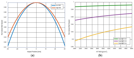
Figure 1.
Rigid body putter ball speed simulation (a) as a function of impact position for two putters and (b) as a function of heel-toe moment of inertia for 3 impact locations.
For the two curves in Figure 1a, only horizontal impact location is varied; vertical impact location is held constant. Ball speed is maximum at the sweet spot (impact position = 0 mm). In general, a putter with large MOI will experience less ball speed loss on off-center impacts compared to one with smaller MOI. The curve for both putters, however, will strongly resemble a parabola using this model.
One can see in Figure 1b, the MOI has a larger effect depending on impact location. At 10 mm from center (green line), the putters at 3000 and 5000 both lose approximately 1% ball speed relative to a center strike. At 30 mm away from center (yellow line), the 3000 putter loses over 10% while the 5000 putter loses only 6.5%.
1.2. Putter Face Milling
Face milling is a common process applied to metal putter heads. It is used to ensure the face is perfectly flat and at the desired loft. Generally, a CNC machine is used with a circular tool that passes across the face at high RPM.
Certain parameters of this process can be modified to create unique and different patterns across the putter face. Some of these include: cutter geometry, tool diameter, tool path, pitch (distance between cuts), and depth. Although often cosmetic, changing the pattern on the face can also result in performance and feel differences. In general, patterns that result in a rougher face feel softer at impact to the golfer.
2. Method
Five face milling patterns were tested to determine their effects on ball speed (Figure 2). A putter pendulum was used to create consistent impact conditions for each putter. Additionally, a putter chassis was used where a face cap can be swapped in and out. This allowed us to ensure each putter tested had identical mass properties, helping isolate any performance differences caused by the face milling. Launch conditions for impacts were captured with a high speed camera system.
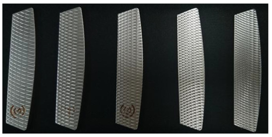
Figure 2.
Face caps (Patterns 1–5) used to test relationship between milling pattern and ball speed.
There are countless variations of the face milling pattern that could be tested. For simplicity, many parameters were held constant for our test. Only one size tool and cutter were used, and the tool path was kept horizontal at a constant offset from the center of the putter face.
Each of these face caps were tested using the setup described previously. The putter pendulum was set to a release height that creates an impact head speed of approximately 3.5 mph. Depending on the green conditions, this represents an approximate 3 m putt. 10 impacts were captured for each pattern, and the median ball speed was recorded. Results are shown in Table 1.

Table 1.
Ball speed of putters tested with different face milling patterns.
The patterns were designed to represent a transition from smooth to rough. One can see that as the milling pattern got deeper and more tightly spaced, the resulting ball speed decreased. The shallowest pattern of these (Pattern 1) resulted in a median ball speed 4% higher than that of the deepest pattern (Pattern 5). These test results can also be plotted in 3D space (Figure 3).
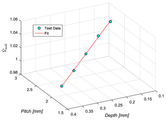
Figure 3.
3D visualization of ball speed as a function of pitch and depth.
The ball speed, , was normalized to the minimum (Pattern 5). It appears from this graph that the subspace was approximately linear. The red curve represents a total least squares linear fit of the test results and can be represented parametrically,
where and are the cutting specs in mm, is the normalized ball speed, and is the parameter.
As mentioned previously, a rigid body mathematical model can be used to predict the ball speed of a putter impact as a function of impact location. The model is an impulse-momentum balance, where face texture is not considered. Unlike the linear results from the pendulum test, this curve (regardless of head speed) is well represented by a parabola (see Figure 1a) of the form,
where is the predicted ball speed in mph and is the impact location horizontally from the sweet spot of the face in mm. For the test putter with known mass properties and matching impact conditions, the coefficients for this equation can be found in Table 2.
Table 2.
Coefficients for ball speed curve from math model with test putter properties.
A new milling pattern is proposed where the depth and pitch vary across the face of the putter. By staying within the linear subspace shown in the robot testing, we can predict the exact effect on ball speed. To make the resulting ball speed curve flat (maximum forgiveness), the following criteria must be met:
It follows that the required pitch and depth, as a function of horizontal position along the face can be calculated from (1)–(3), (6) and (7):
For the example putter, the pitch and depth progression across the face can be plotted together (Figure 4).
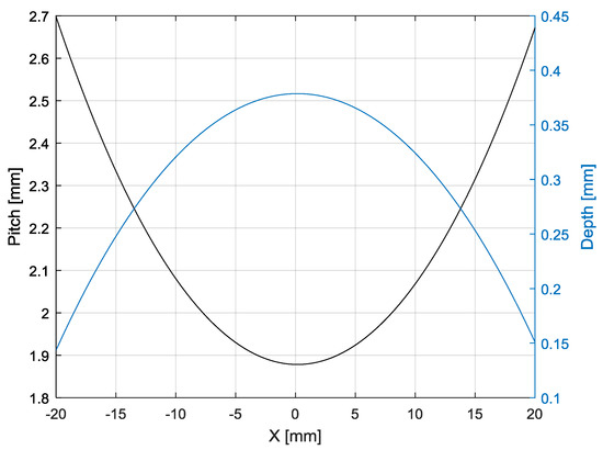
Figure 4.
Pitch and depth progression to normalize ball speed curve.
The result is normalized ball speed curve that is flat over a maximum lateral region of the putter face. The end of normalization occurs at a distance when we are no longer within the pitch/depth model (). Using (8), we can determine the bounds to be for this putter head.
To achieve a flat ball speed curve, the required depth and pitch progression is unique depending on the mass properties of the head. A visualization of this approach applied to multiple putters with different mass properties is shown below (Figure 5). The normalization region extends to 17 mm from center with the low MOI putter and 24 mm from center with the high MOI putter.
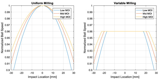
Figure 5.
Normalization for putters with different mass/inertia properties.
3. Results
The variable pitch and depth milling pattern was applied to one head, with known mass properties. Two versions of the head were created, one with the variable milling and one with a traditional, uniform, light milling. These two putters are shown below (Figure 6).
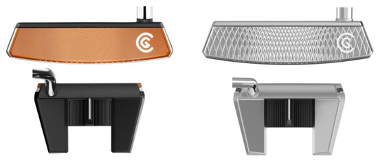
Figure 6.
Putter with light uniform milling (left) and variable milling (right).
Pendulum testing was used to create consistent impacts for each putter at various locations across the face. The impact location and roll-out distance were captured with a camera system. Results are shown below (Figure 7).
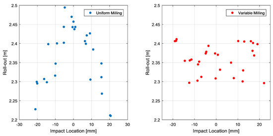
Figure 7.
Roll-out testing for variable milling putter.
As expected, the putter with uniform milling had an approximately parabolic distance dispersion plot (with constant rolling friction, roll-out distance is proportional to the square of the ball’s launch velocity, so this plot would be theoretically represented by a quartic function). The version with variable milling, however, showed a much more linear shape.
4. Discussion
A normalized ball speed curve can have a positive effect on performance. For higher handicap players, who tend to impact the putter with more variation, this effect should be greatest. Poor impacts away from the sweet spot of the putter may travel approximately the same distance as if they were hit at the sweet spot.
The variable milling approach used here can be applied in many other ways. With face milling, there are many properties that can be changed and explored. Horizontal and vertical grooves could be created to achieve a similar performance effect as well. Additionally, a linear model is not necessary. It greatly simplifies things for CNC programming and calculation, but any accurate model of ball speed vs. milling properties could be used to normalize the ball speed curve. Finally, a multi-material face could potentially achieve the same result as well, however it may be more expensive to manufacture.
Assumptions
Although test results appear positive, there are many assumptions that must be kept in mind. The face milling model created with pitch, depth, and ball speed is based on one pendulum test setup (3.5 mph swing speed). It is assumed that this curve holds for other swing speeds, but it certainly will have limitations, especially as head speed increases. The model is also created assuming a center vertical impact. In reality, golfers have a tendency to miss horizontally and vertically. Depending on the shape and path of the variable milling pattern, there could be unintended consequences of high or low impacts on the face.
The milling progression is based on a mathematical rigid body model. Because there are many properties ignored within the model, it may not be as accurate as FEA simulations or empirical testing. Finally, the ball speed normalization does not affect changes in azimuth angle at impact. The torque created from an off-center impact will still exist, and the directional launch angle may be affected.
5. Conclusions
There is much variety in the market for putter shapes and sizes. These putters all have different amounts of forgiveness based on their mass distribution. Many golfers prefer certain putter shapes while disregarding forgiveness. In addition, even the most forgiving putters can result in significant ball speed loss on strikes far from center.
Using a variable depth and pitch milling pattern, ball speed normally lost on off-center hits can be recovered. By considering the exact relationship between the milling properties and ball speed, along with the putter’s inertial response on off-center impacts, this curve can be made perfectly flat within our model. The milling progression required for this normalization is unique to each putter. Robot testing was performed with two identically shaped putters, one with and one without the variable milling pattern. Test results showed a significantly flatter roll-out curve for the variable milled putter.
A putter without ball speed loss on off-center impacts can be beneficial for all players. For high handicap players in particular, gross miss-hits should have better results with a variable milling face optimized for the putter’s mass properties.
Conflicts of Interest
The authors declare no conflict of interest.
References
- Maltby, R. The Complete Book Of Golf Club Fitting & Performance; The GolfWorks: Newark, OH, USA, 2011. [Google Scholar]
- Jorgensen, T.P. The Physics of Golf, 2nd ed.; Springer: New York, NY, USA, 1999; ISBN 0-387-98691. [Google Scholar]
- Petersen, W. Dynamics of Impact Between Golf Club Head and Ball; University of Waterloo: Waterloo, ON, Canada, 2007. [Google Scholar]
Publisher’s Note: MDPI stays neutral with regard to jurisdictional claims in published maps and institutional affiliations. |
© 2018 by the authors. Licensee MDPI, Basel, Switzerland. This article is an open access article distributed under the terms and conditions of the Creative Commons Attribution (CC BY) license (https://creativecommons.org/licenses/by/4.0/).