Abstract
Previous studies have shown how finite element analysis (FEA) can be used to support designers and frame builders in the selection of butted tubes to tune the stiffness and strength behaviour of steel bicycles. The aim of this paper was therefore to analyse the effects of tube butting on the stiffness, stress distribution and energy absorption behaviour of bicycle frames using numerical simulations. Butted tubes were shown to provide a highly effective means to decrease mass whilst producing a disproportionately small change in stress compared with a straight gauge tubeset with a maximum material condition although there was no added benefit in terms of stiffness or strain energy. Conversely, decreasing the wall thickness produced an increase in stress at the tube ends that was disproportionate to the change in mass. This work can now be extended to analyse a fuller set of butted profiles for a range of tube types.
1. Introduction
For over 100 years, frame builders have used off the shelf butted tubing with variable wall thicknesses with the aim to reduce the weight of steel bicycle frames without sacrificing joint strength. Furthermore, recent decades have seen considerable progress in the development of high performance steels, allowing further reductions in frame weight with minimal effect on frame strength. While in this time it has been possible for large scale manufacturers to customise butted tubing profiles for mass produced bicycles, in recent years, customised tubing profiles have become more accessible to small scale frame builders for specialist one-off frame projects [1]. To complement the progress made in materials and manufacturing technologies, the use of numerical simulations is also becoming more common amongst bicycle designers to analyse frame behavior and, where possible, assist in designing more lightweight and fit for purpose bicycles [1,2,3,4,5,6,7,8,9,10,11,12,13,14,15,16,17,18]. Previous studies have shown how finite element analysis (FEA) can be used to support designers in the selection of individual tubes to tune the stiffness and strength behaviour of frames [1,13,15,17,19]. Furthermore, FEA has recently been used to inform the design of individually customised tubes and components using both traditional manufacturing [1] and additive manufacturing technologies [18]. Such tools make it possible to simulate how products perform in the real world and if used appropriately can be used to improve the structural performance of the bicycle. The aim of this paper is therefore to analyse the effects of tube butting on the stiffness, stress distribution and energy absorption behaviour of bicycle frames using numerical simulations.
The steel tubes used to manufacture bicycle frames come in various lengths and diameters for circular, ovular, teardrop and other profiles, and these can be straight gauge, single butted, double butted, triple butted and even quadruple butted profiles. Tubes are typically categorised as either head tube, seat tube, seat stay, chain stay, down tube or top tube. Wide ranges in tube length (up to 780 mm), diameter (typically between 25.4 and 44.5 mm but can be down to 12.8 mm in the seat stays) and wall thickness (down to 0.3 mm in butted tubes) are available through the four main international tube manufacturers Reynolds (UK), Columbus (Italy), True Temper (US) and Tange (Taiwan). A summary table of typical tube options available from these manufacturers can be seen below in Table 1, with the range of strength data for the various steel types can be seen in Table 2. While we were unable to identify published studies which quantify the effects of specific butting profiles on the structural behavior of bicycle frames, a useful introductory account of the effects of material and tube geometry on bending stiffness is provided by [19].

Table 1.
Typical tube details from the four main international tube manufacturers (Reynolds (UK), Columbus (Italy), True Temper (US), Tange (Taiwan)) [19,20,21,22,23,24].
Table 2.
Strength data for various types of steel available through the four main international tube manufacturers (Reynolds (UK), Columbus (Italy), True Temper (US), Tange (Taiwan)) [19,20,21,22,23,24].
2. Methods
Two separate finite element models were created in order to investigate the effects of butting on the stiffness, strength and strain energy of bicycle frames of both the single joint and a whole frame: Model 1—a finite element model of a single brazed joint; and Model 2—a finite element model of a whole frame.
2.1. Model 1—Finite Element Model of a Single Joint
Firstly, a model was created for a single brazed joint of a 60° down tube-head tube assembly in order to isolate the effects of butting on a single joint structure. Figure 1a,b show the geometry/boundary conditions for this model which included a fixed 4 mm brass fillet around the mitred joint to simulate the brazed connection and a set of fixed aluminium bearing cups to hold the head tube in place. There was a surface to surface no-penetration contact between the cups and head tube. Loads were applied through a fixed cylindrical insert into the down tube. This configuration was chosen as it matches an experimental rig created to characterise test joints manufactured by frame builders, although the experimental data is not included in this study.
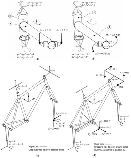
Figure 1.
Geometry/boundary conditions for Model 1 (single down tube-head tube joint with 1-down tube; 2-head tube) in (a) bending and (b) torsion in the down tube; and for Model 2 (whole frame) subjected to (c) in-plane bending due to a road bump at the front wheel, and (d) out of plane bending/torsion due to climbing out of the saddle. Both (c) and (d) were based on loads from [2,3,17].
Linear elastic material properties were assigned to the AISI 4130 steel downtube, head tube and cylindrical insert (E = 205 GPa, ν = 0.29), the 6061-T6 aluminium bearing cups (E = 69 GPa, ν = 0.33) and a representative Ag/Cu/Zn brazing alloy (E = 110 GPa, ν = 0.37) for the fillet. In order to quantify the effects of butting on this single joint, this model was run for three geometric conditions: (i) butted tube profiles for the down tube (t = 0.8/0.5/0.8 mm); (ii) straight gauge tubes using the largest wall thickness (t = 0.8 mm, referred to as the maximum material condition, MMC); and (iii) straight gauge tubes using the smallest wall thickness (t = 0.5 mm, referred to as least material condition, LMC). Solid tetrahedral elements were used to account for the tapered butted profiles in the tubes and a mesh refinement was applied until the results converged within 98% of a target accuracy in the fillet area [25]. In the first instance, a 1 N in-plane bending force was applied to the end surfaces of the cylindrical insert in the direction normal to the long axis of the downtube. In a separate study, a 1 N·m moment was applied to the same location around the same long axis of the downtube. These load cases are depicted in the free body diagrams in Figure 1a,b.
For each load case, the stiffness (k) was calculated by dividing the force or moment load by the deflection or rotation at the end of the downtube, the maximum Von-Mises stress (σ) was noted at an area of interest around the junction between down tube and head tube, and the total strain energy (U) in the tubes was calculated by adding the strain energy in all elements.
2.2. Model 2—Finite Element Model of a Whole Frame Assembly
A whole frame finite element model was also created to understand the effects of butting on the stiffness, stress and strain energy of a complete bicycle frame. This model was used previously in [17], and was extended in this study to allow for tube butting profiles to be accounted for in the top tube, downtube and seat tube and again a mesh refinement was applied until the results converged within 98% of a target accuracy in the fillet area [25]. The frame material properties were the same as in 2.1 above, and the load cases were based on those presented in [2,3,17] for the in-plane bending due to a road bump at the front wheel, and out of plane/torsion due to climbing out of the saddle. These load cases are depicted in the free body diagrams in Figure 1c,d.
3. Results and Discussion
Table 3 shows the effects of butting and tube wall thickness on various performance measures for Model 1 (single joint) and Model 2 (whole frame) subject to in-plane bending and out of plane/torsion loading conditions. Since it was the relative changes in stiffness, stress and strain energy that were of interest here, results have been presented as (i) the % change from the 0.8/0.5/0.8 butted tube benchmark model e.g., Δk % which is unbracketed; and (ii) the ratio of this change to the % change in mass, e.g., (Δk/Δm) which is bracketed. This was in order to understand the overall effect of the changes, but also to understand how these changes are reflected when normalised against the % change in mass.
Table 3.
Influence of tube butting profiles on stiffness (k), stress (σ), strain energy (U) and mass (m) for Model 1 (single joint: mass of down tube + head tube = 0.354 kg) and Model 2 (whole frame: total mass = 2.19 kg), for in-plane bending and torsion loading conditions. Since the relative changes are of interest here, results are presented as (i) a % change from the 0.8/0.5/0.8 butted tube benchmark model , e.g., Δk % which is unbracketed; and (ii) the ratio of this change to the % change in mass, e.g., (Δk/Δm) which is bracketed (apart from the mass column where the actual mass is presented in brackets).
The results suggest that using butted tubes generally provided a highly effective means to decrease mass with a disproportionately small change in stress although the effects on the stiffness and the total strain energy were mixed. Decreasing the wall thickness to a straight gauge LMC (0.5 mm) produced a disproportionately large increase in bending stress at the tube ends of 67.7% and 39.3% for the single joint and whole frame respectively. Similar results were obtained for the LMC in torsion, with stress increasing by 47.7% and 41.2% for the single joint and whole frame respectively when compared with the butted tubes. Conversely, increasing the wall thickness to the straight gauge MMC throughout (0.8 mm) produced almost no changes in the stresses in bending or torsion apart from the single joint in bending which produced only a 16.2% reduction in stress (for a 25.6% increase in mass).
In terms of bending stiffness, the difference between butted and straight gauge tubing was less dramatic than that of the stress results which were presented in the previous paragraph. The change in bending stiffness was limited to a maximum of 25.7% (whole frame), while the change in torsional stiffness was limited to only 27.0% (single joint). Overall, the reduction in these stiffness values was in line with the reduction in second moment of area, I, since the bending moment in these load cases was linear along the tube length, which was also noted in [2]. Similarly for the out of plane/torsion load cases, the constant 1 N · m torque along the length of the tube resulted in an overall reduction in stiffness that was in line with the changes in the polar second moment of area, J.
In terms of strain energy, the magnitude of the difference between butted and straight gauge tubing was similar to that of bending stiffness, since the strain energy is inversely proportional to the stiffness. The change in strain energy was limited to 27.1% in bending (whole frame) and 23.3% in torsion (single joint). As such, there appears to be no real advantage gained in using butted tubing when considering the energy absorbed within the frame. Thinner tubing will absorb more strain energy in line with the changes in I and J.
It is worth noting that in Model 2 (whole frame) the influence of butting on both the stiffness and strain energy was approximately double that of the single joint scenario. In this model only the tubes in the front triangle were butted, and those tubes made up just over half of the total frame mass (55.2%), yet these tubes contribute the most to the overall frame stiffness and strain energy of a bicycle frame in these load conditions [3]. One of the limitations here was that only a single butting profile has been considered here in isolation. As Table 1 suggests, there are a wide variety of butting profile combinations of wall thickness that can be used to ‘tune’ the structural behavior of the bicycle frame. Varying combinations of tube diameter and steel strength are also means to further influence the frame behaviour and we have not considered such combinations in this study, however our approach could now be extended to include such combinations and compared to other numerical models such as [9] and analytical models also.
4. Conclusions
Butted tubes can provide a highly effective means to decrease mass whilst producing a disproportionately small change in stress although there was no advantage in terms of stiffness and the total strain energy in this study. Conversely, decreasing the wall thickness to LMC (0.5 mm) produced a disproportionately large increase in stress at the tube ends, with similar increases to MMC (0.8 mm) producing a disproportionately small decrease in stress. While only a single butting profile has been considered in this study, our approach could now be applied to a wide range of parametric combinations of butting wall thicknesses, tube diameters and steel strengths to support bicycle designers in the selection of individual tubes to tune the stiffness and strength behaviour of frames.
Conflicts of Interest
The authors declare no conflict of interest.
References
- Paulus, J. Designing the Ultimate Bicycle, Presentation: Bespoked Bristol. 7 April 2017. [Google Scholar]
- Soden, P.; Millar, M.; Adefeya, B.; Wong, Y. Loads, stresses and deflections in bicycle frames. J. Strain Anal. 1986, 21, 185–195. [Google Scholar] [CrossRef]
- Peterson, L.; Londry, K.; A New Tool for Bicycle Frame Design: The Strain Energy Design Method. In Bike Tech: Bicycling Magazine's Newsletter for the Technical Enthusiast; 1986. Available online: https://www.sheldonbrown.com/rinard/fea.htm (accessed on 1 August 2017).
- Hull, M.; Bolourchi, F. Contributions of rider-induced loads to bicycle frame stress. J. Strain Anal. 1988, 23, 105–114. [Google Scholar] [CrossRef]
- Lessard, L.; Nemes, J.; Lizotte, P. Utilization of FEA in the design of composite bicycle. Composites 1995, 26, 72–74. [Google Scholar] [CrossRef]
- Maestrelli, L.; Falsini, A. Bicycle frame optimization by means of an advanced gradient method algorithm. In Proceedings of the 2nd European HTC, Strasbourg, France, 30 September–1 October 2008. [Google Scholar]
- Finn, J. Application of optimisation tools to the design of advanced carbon fibre bicycle: Factor 001. In Proceedings of 6th Altair CAE Technology Conference, Warwickshire, UK, 14 April 2009. [Google Scholar]
- Liu, T.; Wu, H. Fiber direction and stacking sequence design for bicycle frame made of carbon/epoxy composite laminate. Mater. Des. 2010, 31, 1971–1980. [Google Scholar] [CrossRef]
- Reynolds Technology Ltd. eReynolds Manual for eReynolds Software; Provided by Reynolds Technology through Correspondence; Reynolds Technology Ltd.: Birmingham, UK, 2011. [Google Scholar]
- Callens, A.; Bignonnet, A. Fatigue design of welded bicycle frames using multiaxial criterion. Procedia Eng. 2012, 24, 640–645. [Google Scholar] [CrossRef]
- Dwyer, F.; Shaw, A.; Tombarelli, R. Material and Design Optimization for an Aluminium Bike Frame. BSc Project Thesis, Worcester Polytechnic Institute, Worcester, MA, USA, 2012. [Google Scholar]
- Miles, P.; Archibald, M. Experimental investigation of bicycle frame FEA models. In Proceedings of the IMECE, San Diego, CA, USA, 15–21 November 2013. [Google Scholar]
- Covill, D.; Begg, S.; Elton, E.; Milne, M.; Morris, M.; Katz, T. Parametric finite element analysis of bicycle frame geometries. Procedia Eng. 2014, 72, 441–446. [Google Scholar] [CrossRef][Green Version]
- Daugherty, C.; Follstaedt, G.; Archibald, M. Light Alternative Vehicle Frame Fatigue Failure prediciton and prevention. In Proceedings of the ASEE Conference, Indianapolis, IN, USA, 15–18 June 2014. [Google Scholar]
- Covill, D.; Blayden, A.; Coren, D.; Begg, S. Parametric finite element analysis of steel bicycle frames: The influence of tube selection on frame stiffness. Procedia Eng. 2015, 112, 34–39. [Google Scholar] [CrossRef]
- Tayade, B.; Deshmukh, T. A comparative study on structural health of bicycle frame using finite element analysis—A review. Int. J. Pure Appl. Res. Eng. Technol. 2015, 3, 176–183. [Google Scholar]
- Covill, D.; Allard, P.; Drouet, J.-M.; Emerson, N. An assessment of bicycle frame behaviour under various load conditions using numerical simulations. Procedia Eng. 2016, 147, 665–670. [Google Scholar] [CrossRef]
- Colins, P.; Leen, R.; Gibson, I. Industry case study: Rapid prototype of mountain bike frame section. Virtual Phys. Prototyp. 2016, 11, 295–303. [Google Scholar] [CrossRef]
- Brown, B. Engineering: Material Myths. 2007. Available online: http://www.bobbrowncycles.com/eng.htm (accessed on 1 August 2017).
- Tange International Ltd. Available online: https://www.tange-design.com/tubing_list.php (accessed on 1 August 2017).
- True Temper Sports. Available online: http://www.henryjames.com (accessed on 1 August 2017).
- Columbus Tubing Catalogue. Available online: http://www.columbustubi.com/pdf/Columbus-Tubi-2017-Catalogue-V2.pdf (accessed on 1 August 2017).
- Reynolds technology Ltd. Cycle Frame Tube Price List; Reynolds Technology Ltd.: Birmingham, UK, 2015. [Google Scholar]
- Strong Frames Custom Bicycles. Bicycle Frame Tube Information. Available online: http://www.strongframes.com/tubing-information/ (accessed on 1 August 2017).
- Abambres, M.; Arruda, M. Finite element analysis of steel structures—A review of useful guidelines. Int. J. Struct. Integr. 2016, 7, 490–515. [Google Scholar] [CrossRef]
Publisher’s Note: MDPI stays neutral with regard to jurisdictional claims in published maps and institutional affiliations. |
© 2018 by the authors. Licensee MDPI, Basel, Switzerland. This article is an open access article distributed under the terms and conditions of the Creative Commons Attribution (CC BY) license (https://creativecommons.org/licenses/by/4.0/).