1. Introduction
In a world in which living without electricity is almost unconceivable, wind energy represents a power source becoming cheaper and more competitive in the course of time. Nowadays, more than 3% of the world energy consumption is supplied by wind energy. This number is expected to rise above 5% in 2020 [
1]. It is inexhaustible, renewable and non-contaminant. In addition, the use of wind energy helps to reduce the dependence on fossil fuels. For all these reasons, the development of improvements and innovations regarding wind turbines and the aerodynamic airfoils employed to build the blades is a topic of great interest. Wind turbines may be classified with respect to the orientation of the rotor axis in horizontal and vertical axis wind turbines (HAWTs and VAWTs). Although research has been traditionally focused on HAWTs, VAWTs present important advantages, being the main one that they are capable of working independently of the wind direction.
In this work, an airfoil shape optimized for vertical-axis wind turbine applications is proposed. Different airfoil shapes have been analyzed with a panel method, using the results from the analysis in order to optimize the performance of a new airfoil shape. This airfoil presents a high lift-to-drag ratio and a delayed stall angle with respect to the previously analyzed airfoils, which makes it suitable for vertical-axis wind turbine applications.
2. Airfoil Aerodynamics
The force exerted by an incoming wind flow on an airfoil may be decomposed into a component in the direction of the wind (drag) and another perpendicular to it (lift). Following this force decomposition, vertical axis wind turbines may be divided in drag-driven and lift-driven turbines. Nowadays, lift-driven VAWTs are of much greater interest because the magnitude of lift forces on an airfoil is generally 2 orders of magnitude higher than drag forces. Thus, the main focus of research is the maximization of lift and the reduction of drag in airfoils.
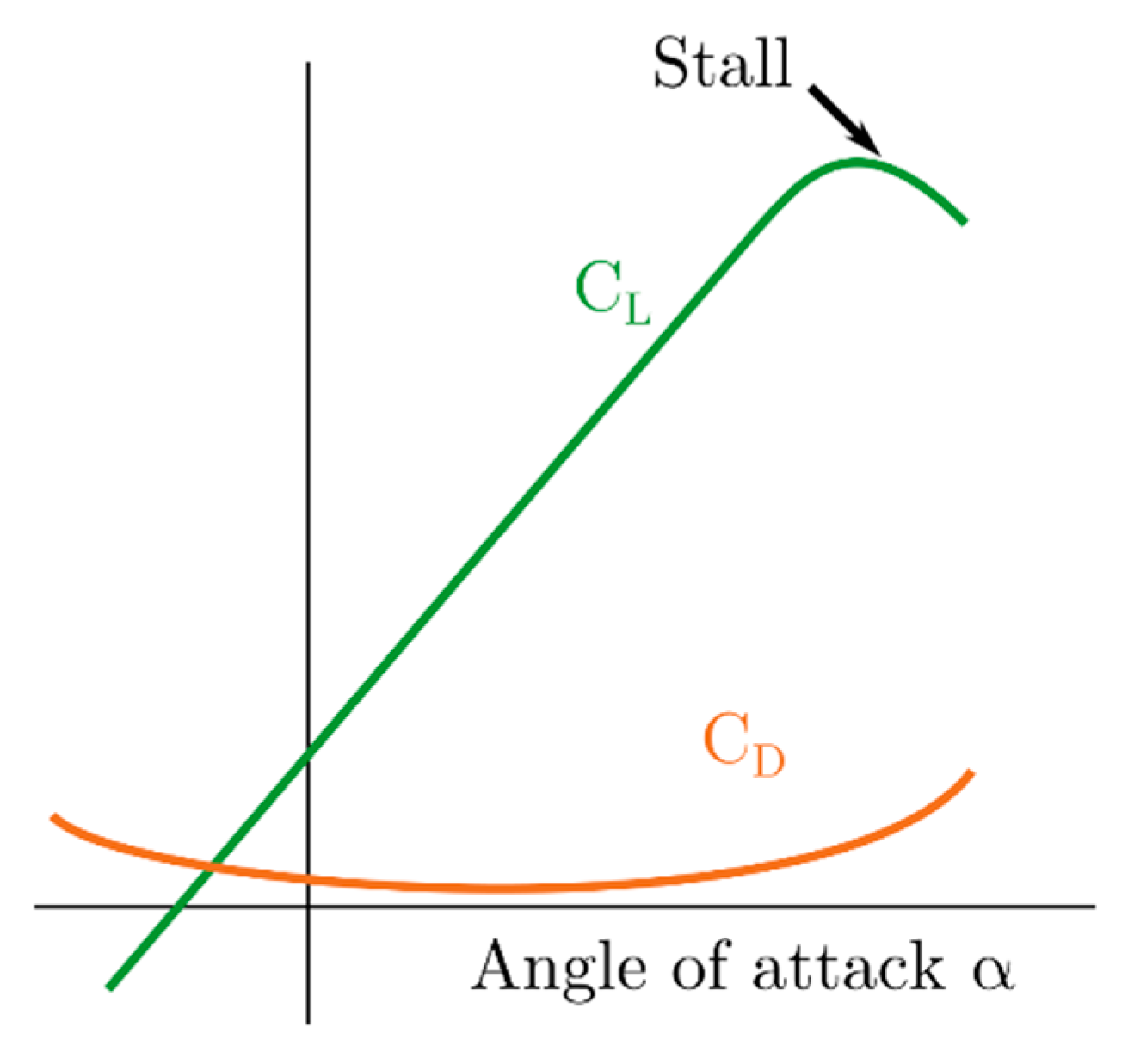
Figure 1 shows the typical evolution of lift and drag coefficients with the angle of attack. Regarding the airfoil geometry, the main geometrical characteristics affecting the performance of an airfoil are its maximum thickness, maximum camber and their situation with respect to the leading edge of the airfoil.
3. Methodology: Panel Methods
Panel methods are a type of numerical method for the resolution of potential flow problems. They start from the discretization of the surface of the object under study, introducing an unknown potential term in every surface segment. Then, the influence of the free stream and the relative influences of every potential term are collected in an influence matrix. Finally, solving the equation system formed by this matrix and a vector of geometrical coefficients, the pressure over each segment is obtained and the problem is solved [
2].
In this work, a free software (JavaFoil [
3]) that combines the potential flow method with a boundary layer analysis has been applied. It has been proved that this software is capable of achieving a good prediction of the aerodynamic behavior of airfoils at low angles of attack.
A total of 17 airfoils selected from the bibliography have been analyzed in this study, in order to provide insight into the desirable geometrical features of an airfoil for lift-driven VAWTs. The main characteristics of these airfoils are collected in
Table 1.
The verification of the panel method has been performed by verifying the independence of the discretization of the geometry. Afterwards, the results have been compared with experimental results [
4,
5] for the final validation of the methodology. The results obtained with JavaFoil, although starting to distance from the experimental results as the airfoil reaches the stall angle, are accurate enough at the linear part of the lift curve, and thus may be considered as valid for the purpose of preliminary airfoil design and comparison of different airfoil geometries.
4. Results
It was found that an increase on the airfoil thickness led to more significant lift production and a delay on the stall angle of the airfoil. Higher Reynolds numbers were related to an improvement in the performance of the airfoils. Finally, the addition of a small amount of camber to a symmetrical airfoil increases the lift and decreases the drag values with respect to the symmetrical one, but at the cost of a slight decrease in the stall angle. It was found that thickness values around 18 and 21% and camber values below 4% offer the best results. The airfoils showing the best performances are the NLF(1)-0115, FX-63-137 and S1012.
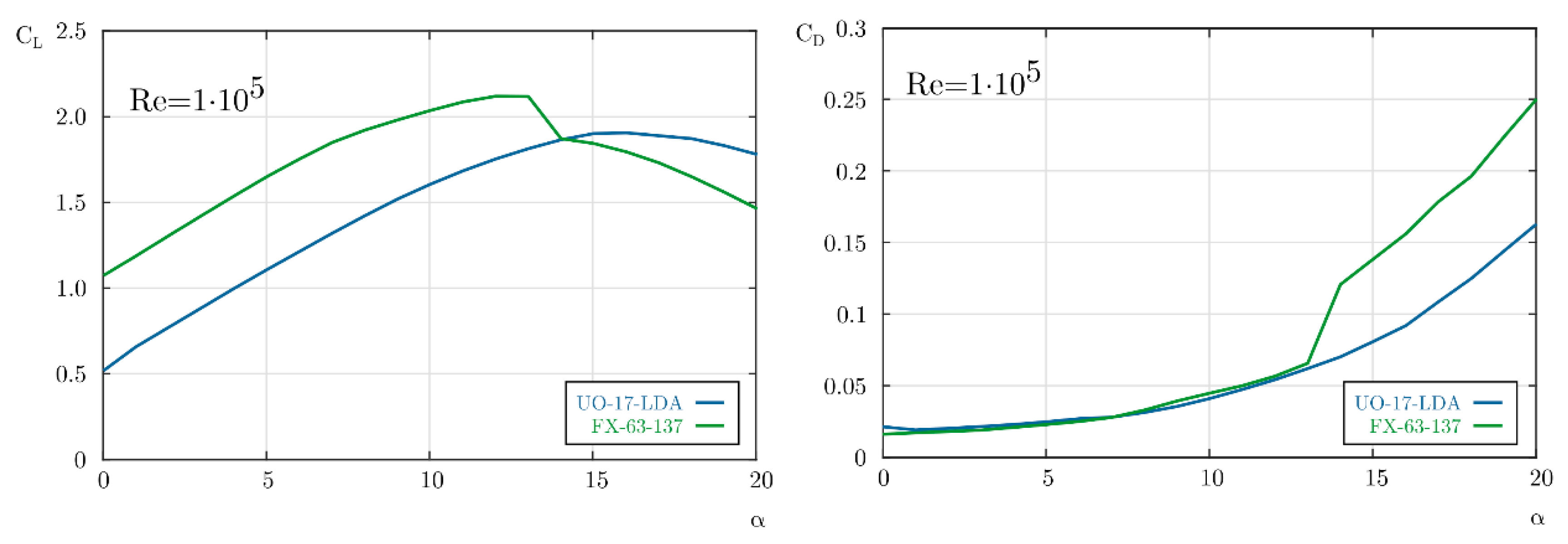
Then, five different airfoils were proposed modifying these three airfoils with the optimal values of thickness and camber found in this study, and the one with the highest lift/drag ratio and with a sufficient delay in the stall angle, UO-17-LDA, was selected as the optimal one. This airfoil has a thickness of 21% and a camber of 2%. The comparison of the performance of this proposed airfoil with the original one, FX-63-137, showed that the airfoil proposed has a stall angle 5° higher than the original one, and presents lower drag values, as depicted in
Figure 2. Hence, the proposed airfoil seems more suitable for its use in vertical axis wind turbines.
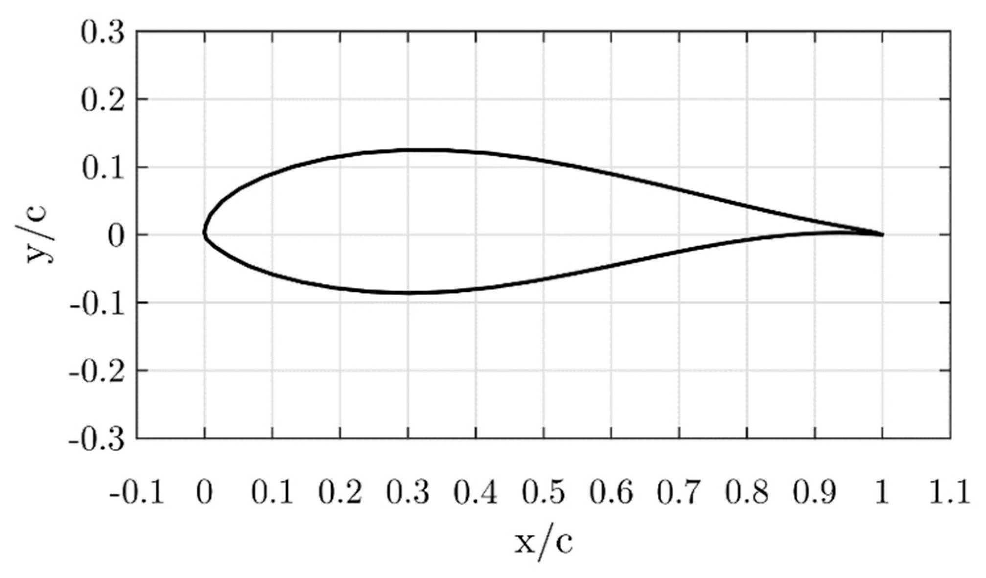
Figure 3 shows the outline of the UO-17-LDA airfoil.
5. Conclusions
The influence of the geometrical characteristics of an airfoil is determining on its performance. Lift and drag, as well as the stall angle, depend on the thickness and camber of the airfoil, apart from the Reynolds number. In addition, the positions of maximum thickness and camber also determine the performance of the airfoil. It has been found that thickness values around 18 and 21% and camber values below 4% offer the best results. The airfoil proposed in this study, UO-17-LDA, is a modification of the FX-63-137 airfoil with the optimum values for thickness and camber found in this work, 21% thickness and 2% camber. A delay in stall of 5° with respect to the original airfoil has been observed using the software JavaFoil, based on a panel method with a coupled boundary layer analysis. The lift coefficient of the proposed airfoil is only slightly lower than for the original airfoil, and the increase of the stall angle makes the UO-17-LDA airfoil suitable for its use in vertical-axis wind turbines.
Author Contributions
All the authors contributed substantially to this work during the different stages: design of the study, validation of the method, selection and evaluation of the different airfoil geometries and proposal and evaluation of an optimal one. A.M.-F. collected all the results and wrote the paper.
Acknowledgments
This work has been supported by the “FPU” predoctoral research scholarship provided by the Spanish Ministry of Education, Culture and Sports. The authors also want to acknowledge the support from the Projects “Desarrollo de una herramienta de diseño optimizado de perfiles aerodinámicos para su utilización en turbinas eólicas de eje vertical” (SV-15-GIJON-1-09) from the University Institute of Industrial Technology of Asturias, financed by the City Council of Gijon, Spain, “Diseño optimizado de una turbina eólica de eje vertical” from the University of Oviedo Foundation, financed by the company AST Ingeniería and “Desarrollo y construcción de turbinas eólicas de eje vertical para entornos urbanos” (ENE2017-89965-P) from the Spanish Ministry of Science, Innovation and Universities.
Conflicts of Interest
The authors declare no conflict of interest. The founding sponsors had no role in the design of the study; in the collection, analyses, or interpretation of data; in the writing of the manuscript, and in the decision to publish the results.
References
- Sawyer, S.; Rave, K. Global Wind Report—Annual Market Update; Technical Report; Global Wind Energy Council (GWEC): Brussels, Belgium, 2015. [Google Scholar]
- Hess, J. Panel methods in Computational Fluid Dynamics. Ann. Rev. Fluid Mech. 1990, 22, 255–274. [Google Scholar] [CrossRef]
- Javafoil—Analysis of Airfoils. Available online: https://www.mh-aerotools.de/airfoils/javafoil.htm (accessed on 28 May 2018).
- Claessens, M.C. The Design and Testing of Airfoils for Application in Small Vertical Axis Wind Turbines. Master’s Thesis, TU Delft, Delft, The Netherlands, 2006. [Google Scholar]
- Sheldal, R.E.; Klimas, P.C. Aerodynamic Characteristics of Seven Symmetrical Airfoil Sections through 180-Degree Angle of Attack for Use in Aerodynamic Analysis of Vertical Axis Wind Turbines; Technical Report SAND80-2114; Sandia National Laboratories: Albuquerque, NM, USA, 1981. [Google Scholar]
| Publisher’s Note: MDPI stays neutral with regard to jurisdictional claims in published maps and institutional affiliations. |
© 2018 by the authors. Licensee MDPI, Basel, Switzerland. This article is an open access article distributed under the terms and conditions of the Creative Commons Attribution (CC BY) license (https://creativecommons.org/licenses/by/4.0/).


