Proceeding Paper

Gurney Flap Implementation on a DU91W250 Airfoil †

1
Nuclear Engineering and Fluid Mechanics Department, University of the Basque Country UPV/EHU, 01006 Vitoria-Gasteiz, Spain
2
Automatic Control and System Engineering Department, University of the Basque Country UPV/EHU, 01006 Vitoria-Gasteiz, Spain
3
Mechanical Engineering Department, University of the Basque Country UPV/EHU, 01006 Vitoria-Gasteiz, Spain
*
Author to whom correspondence should be addressed.
Presented at the 2nd International Research Conference on Sustainable Energy, Engineering, Materials and Environment (IRCSEEME), Mieres, Spain, 25–27 September 2018.
Proceedings 2018, 2(23), 1448; https://doi.org/10.3390/proceedings2231448
Published: 6 November 2018

Abstract

:
The increasing capability of Wind Turbine (WT) based power generation systems has derived in an increment of the WT rotor diameter, i.e., longer rotor blades. This results in an increase of the electrical power generated but also in instabilities in the operation of the WT, especially due to the mechanical fatigue loads generated in its elements. In this context, flow control has appeared as a solution to improve the aerodynamic performance of the blades. These devices not only increase lift coefficient but also reduce mechanical fatigue loads. This paper presents a detailed numerical analysis of the effects of placing a passive flow control element, a Gurney Flap (GF), in a DU91W250 airfoil. Moreover, a numerical study of the influence of the GF length on the aerodynamic performance of the blade has been carried out. This study is considered as a basis for the development of an optimization technique of the GF length for long WT blades.

1. Introduction

Increasing capability and installed power of wind-based generation systems has caused the development of bigger rotor wind turbines (WTs), i.e., longer rotor blades. As Aramendia et al. [1] mentioned, the higher the size of a wind turbine is, the higher the structural and fatigue loads are and the thicker the root sections have to be. These form and operation limitations have a negative effect on the aerodynamics of the blades, since they cause an earlier separation of the boundary layer in the suction side of the mid-outer parts of the blade. In this context, strategies aimed to avoid the premature separation of the boundary layer have gained in significance over the last years. These techniques, compiled by Johnson et al. [2], are known as flow control techniques. They can be divided in two big groups: Active and passive flow control techniques. Active flow control techniques need an external energy source for their performance whereas passive flow control techniques do not need it, so their cost is lower.
Among passive flow control devices, Gurney Flaps (GFs) are gaining importance and popularity due to their simplicity, low cost and good performance. A Gurney Flap (GF) is a vane perpendicular to the airfoil surface and with a size between 0.1% and 3% of the airfoil chord length. They can be placed either in the lower or in the upper side of airfoil, close to the trailing edge, as shown in Figure 1a. Fernandez-Gamiz et al. [3] studied the effect of Vortex Generators and Gurney Flaps on the power output performance of a 5 MW wind turbine. As mentioned by Jeffrey et al. [4], GFs were first used for increasing downforce and improving stability of a vehicle in racing applications by the race car driver Daniel Gurney in the late 1960s.
In case of a WT, these devices are aimed to increment the lift force of the blades, increasing mechanical torque applied by the wind in the rotor, see Figure 1b. In previous articles on this field, Storms et al. [5] checked an increment of almost 15% in the lift force with a GF with a length of 0.5% of the cord of the airfoil. Roncero et al. [6] showed a considerable increment of the lift coefficient for every angle of attack (AoA) of the incoming airflow, using a 0.25% chord length GF on a DU91(2)W250 airfoil. In both cases, the increment of the drag force is insignificant in comparison with the increment of the lift force. Mohammadi et al. [7] studied the effect of different passive flow control elements for a DU91W2250 airfoil. In all cases, there was an increase in the lift coefficient in comparison with the clean airfoil and a decrease in the lift/drag relation. In a direct comparison between the three devices studied, GFs obtained the biggest lift coefficient increment.
The objective of this study is the development of an optimization technique for the GF length for different wind and/or rotor blade airfoil geometry scenarios. Furthermore, a parametrical study will be made to study the effect of the GF length and its implications in the WT control system. For this purpose, CFD simulations will be carried out and the validation of the simulation data will be achieved with the experimental data provided by Timmer et al. [8].

2. Test Cases

Flow control devices are presented in the literature as useful techniques to improve aerodynamic performance and to reduce mechanical fatigue loads in WT blades. In this article, a passive flow control device, Gurney Flap, is studied in detail. In order to characterize the effect of the GF length in the aerodynamic behavior of a DU91W250 airfoil, several test cases have been considered. Each test case corresponds to a different GF length, expressed as a percentage of the airfoil chord length. Test cases in the scope of this article are summarized in Table 1.
Aerodynamic performance of an airfoil is determined by its lift and drag coefficients. In this paper, to fully characterize the effect of the GF length in the aerodynamic performance of the airfoil, lift and drag coefficients of the airfoil are calculated for each one of the test cases.

3. Computational Setup

Computational Fluid Dynamics (CFD) simulations have been used to study the effects of a GF on a DU91W(2)250. An O-mesh type was created defining a structured mesh, as illustrated in Figure 2. Steady state simulations were carried out using Reynolds Averaged Navier-Stokes (RANS) equations with the k-ω SST shear stress turbulence model. A uniform free stream velocity was set for all the simulations by means of a Mach number of Ma = 0.0882 corresponding to a Reynolds number of Re = 2 × 10⁶.

4. Results

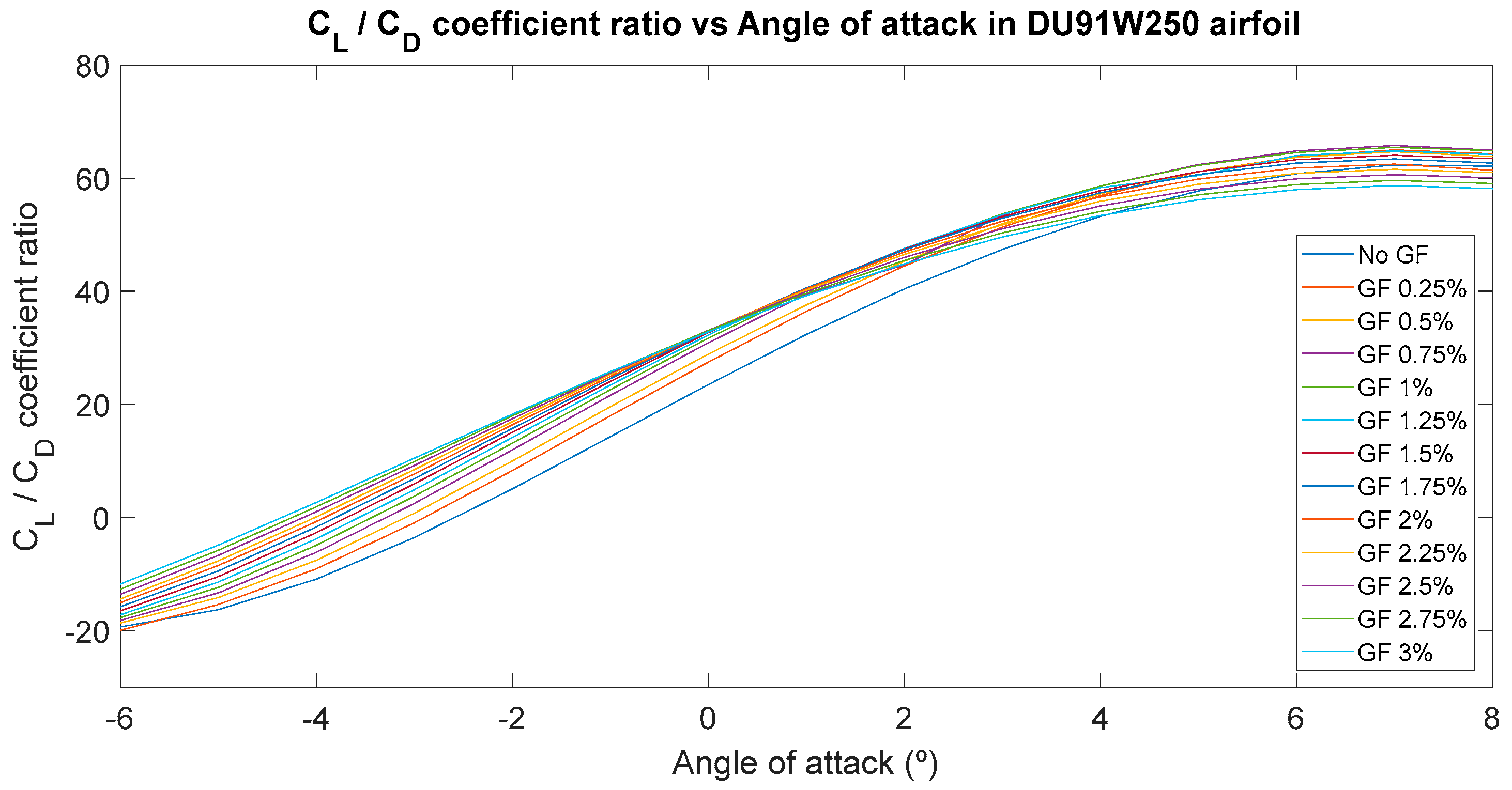
Lift and drag coefficients were calculated with the expressions (1) and (2). Figure 3 shows the results of the CL/CD relation in the CFD simulations for all angles of attacks of the airfoil analyzed.
C L = L 1 2 ρ U 2 c
C D = D 1 2 ρ U 2 c
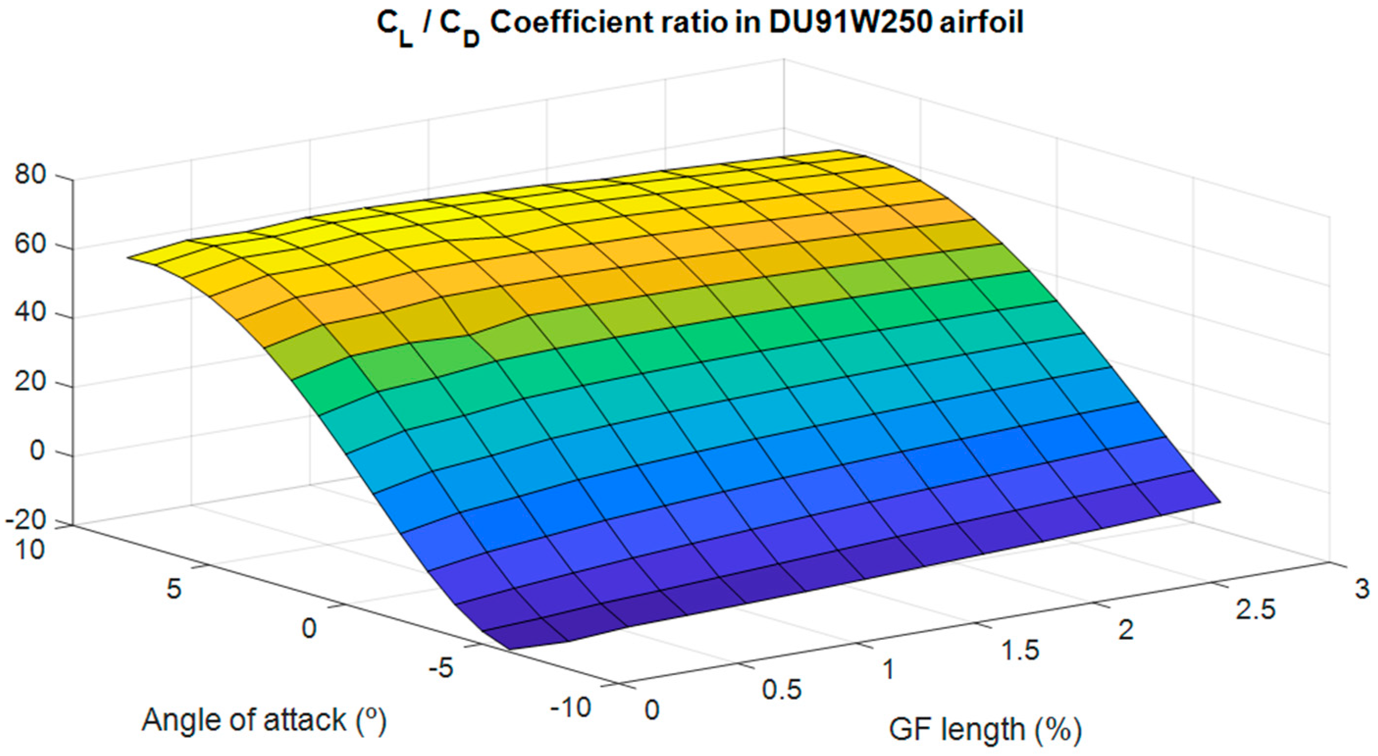
Finally, Figure 4 shows a 3D representation of the lift/drag coefficient ratio with respect to the angle of attack of the incoming wind and the length of the GF. This 3D curve allows to obtain a mathematical expression that relates the evolution of the lift coefficient in a DU91W250 airfoil with the AoA and the GF length as the only variables, as shown in expression (3).
z = 24.02 + 1.319 · x + 6.197 · y
Variables x, y and z represent the GF length (%), the AoA ( ° ) and the Lift/Drag coefficient ratio.

5. Conclusions

It was observed that the Lift/drag ratio depends on the AoA and the GF length in a non-linear way, since the maximum value for positive AoA is achieved with a GF of 0.75% of c and with a GF of 0.25% of c for negative AoA. It must be noted that the AoA range considered for the analysis lies from −6° to 8°. This is due to the fact that beyond 8° the curve of the lift coefficient is highly non-linear, and simulation results could not be as clear as in the linear region.

Author Contributions

I.A., A.S.-A., U.F.-G. and E.Z. conceived and performed the CFD simulations; J.M.L.-G. A.B. and J.S. analyzed the results and provided constructive instructions in the process of preparing the paper.

Acknowledgments

The authors are grateful to the Government of the Basque Country and the University of the Basque Country UPV/EHU through the SAIOTEK (S-PE11UN112) and EHU12/26 research programs, respectively. The funding of Fundation Vital Fundazioa is also acknowledged.

Conflicts of Interest

The authors declare no conflict of interest.

References

  1. Aramendia, I.; Fernandez-Gamiz, U.; Ramos-Hernanz, J.A.; Sancho, J.; Lopez-Guede, J.M.; Zulueta, E. Flow Control Devices for Wind Turbines. Energy Harvest. Energy Effic. Technol. Methods Appl. 2017, 37, 629–655. [Google Scholar] [CrossRef]
  2. Johnson, S.J.; van Dam, C.P.; Berg, D.E. Active Load Control Techniques for Wind Turbines. Sandia Report; SAND 2008-4809; Sandia National Laboratories: Livermore, CA, USA, 2008. [Google Scholar]
  3. Fernandez-Gamiz, U.; Zulueta, E.; Boyano, A.; Ansoategui, I.; Uriarte, I. Five Megawatt Wind Turbine Power Output Improvements by Passive Flow Control Devices. Energies 2017, 10, 742. [Google Scholar] [CrossRef]
  4. Jeffrey, D.; Zhang, X.; Hurst, D. Aerodynamics of Gurney flaps on a single-element high-lift wing. J. Aircr. 2000, 37, 295–301. [Google Scholar] [CrossRef]
  5. Storms, B.; Jang, C. Lift Enhancement of an Airfoil using a Gurney Flap and Vortex Generators. J. Aircr. 1994, 31, 542–547. [Google Scholar] [CrossRef]
  6. Roncero, G.; Saenz, P.; Fernandez-Gamiz, U.; Errasti, I.; Zulueta, E.; Lopez-Guede, J.M.; Sancho, J. Computational Characterization of a Gurney Flap on a DU91(2)W250 Airfoil; International Conference on Materials and Energy: San Sebastian, Spain, April 2018. [Google Scholar]
  7. Mohammadi, M.; Doosttalab, A.; Doosttalab, M. The effect of various gurney flaps shapes on the performace of wind turbine airfoils. In Proceedings of the ASME Early Career Technical Conference, Atlanta, GA, USA, 2–3 November 2012. [Google Scholar]
  8. Timmer, W.; van Rooij, R. Summary of the Delft University wind turbine dedicated airfoils. J. Sol. Energy Eng. Trans. ASME 2003, 125, 488–496. [Google Scholar] [CrossRef]
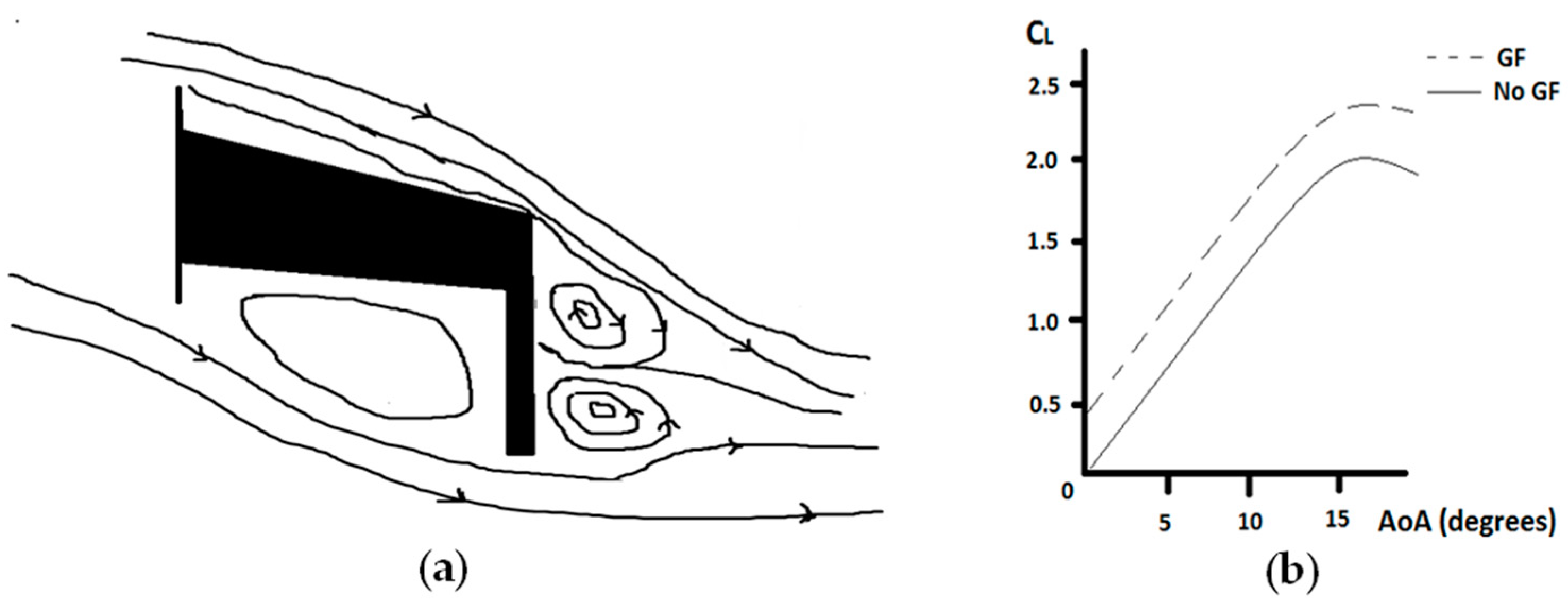
Figure 1. (a) GF placed in the suction side of a WT airfoil; (b) Lift coefficient improvement with GF.
Proceedings 02 01448 g001
Figure 2. Mesh distribution on the DU91W(2)250 and on the airfoil trailing edge with a Gurney Flap.
Proceedings 02 01448 g002
Figure 3. Lift coefficient vs Angle of attack in DU91W250 airfoil for different GF length values.
Proceedings 02 01448 g003
Figure 4. Lift/Drag coefficient ratio vs Angle of attack and GF length in DU91W250 airfoil.
Proceedings 02 01448 g004
Table 1. Test cases considered.
Test IDTEST CASEDescription
0DU91W250DU91W250 airfoil without GF
1DU91W250GF025DU91W250 airfoil with GF of length 0.25% of c
2DU91W250GF05DU91W250 airfoil with GF of length 0.5% of c
3DU91W250GF075DU91W250 airfoil with GF of length 0.75% of c
4DU91W250GF1DU91W250 airfoil with GF of length 1% of c
5DU91W250GF125DU91W250 airfoil with GF of length 1.25% of c
6DU91W250GF15DU91W250 airfoil with GF of length 1.5% of c
7DU91W250GF175DU91W250 airfoil with GF of length 1.75% of c
8DU91W250GF2DU91W250 airfoil with GF of length 2% of c
9DU91W250GF225DU91W250 airfoil with GF of length 2.25% of c
10DU91W250GF25DU91W250 airfoil with GF of length 2.5% of c
11DU91W250GF275DU91W250 airfoil with GF of length 2.75% of c
12DU91W250GF3DU91W250 airfoil with GF of length 3% of c
Publisher’s Note: MDPI stays neutral with regard to jurisdictional claims in published maps and institutional affiliations.