1. Introduction
The straight adaptability of the Radio Frequency Identification (RFID) technology to the demands of the supply chain is continuously increasing its popularity. Applications such as the goods tracking and monitoring, traceability of patients or managing the medication of elderly in health-care have presented promising improvements thanks to RFID [
1].
A basic RFID system is composed of a reader and one or several tags. The reader interrogates tags by transmitting radio frequency (RF) signals containing commands. Tags are simple devices that respond with their Electronic Product Code (
) and can be active or passive. Active tags are powered with batteries, whilst passive tags use the reader signal to power up their circuitry. The latter devices are becoming attractive due to their low cost (≈10 cents), a small sticker form factor, and the operation range of over 10 meters from the reader. Additionally, there is an increasing interest in passive tags thanks to Computational RFID (CRFID) systems [
2]. Several research applications have been proposed exploiting the potential of CRFID in environment monitoring [
3], activity recognition [
4] or the battery-free camera [
5]. These systems use passive tags containing a programmable micro-controller and a battery-less sensor which are powered using the reader RF signal and respond backscattering, not only their
code but also the value of their sensor.
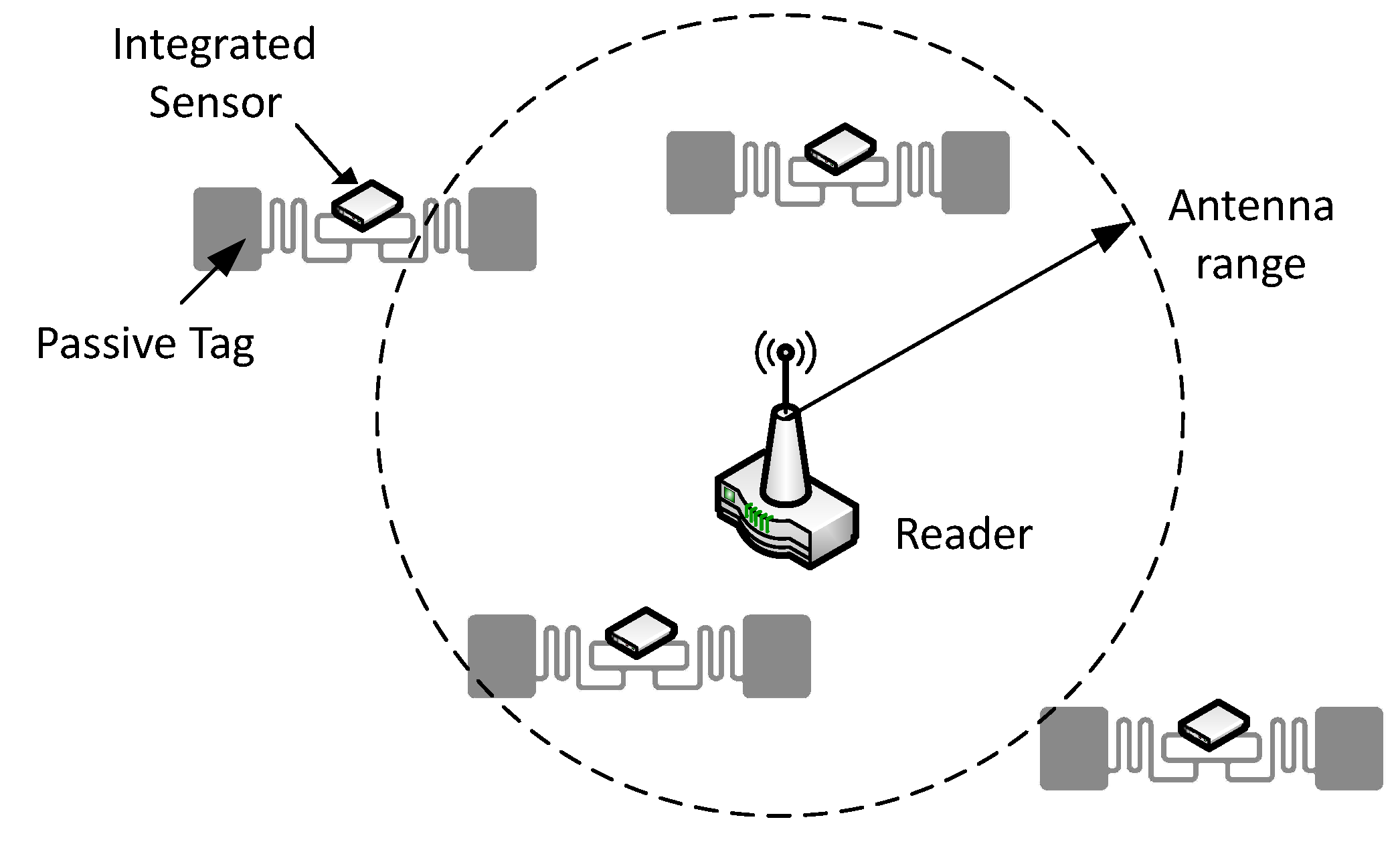
These passive sensors together with the reader set up an RFID sensor network (see
Figure 1) which offers the potential for densely distributed sensing that inherits the already mentioned attractive features of RFID. Several solutions are exposed in the literature in terms of integrating RFID with Wireless Sensor Networks (WSN) [
6,
7] to improve their capabilities and the applicability of both systems to the real world. A way of integrating RFID and WSNs is the incorporation of sensing capabilities to RFID tags. This paper is focused on the case where one reader interrogates several distributed CRFID tags.
RFID sensor networks use the same protocols and mechanisms for reading tags
codes and collecting their sensed data [
8]. This fact makes the sensing process very inefficient because the reader has to face the tag collision problem first, identify all the tags in the range of the antenna, and then collect sensed data. The current standard used in RFID to identify tags overcoming the tag collision problem is the EPCglobal class 1 Gen 2 protocol (EPC C1G2) [
9]. This is an arbitration oriented protocol used in every commercial reader, also included in ISO 18000-6C. However, the main purpose of this protocol is not sensor reading and therefore, it presents poor efficiency when streaming sensor data. The data coming from the sensors gets broken into packets, highly increasing the overhead of the reading process.
In order to improve the performance of the standard EPC C1G2 when streaming sensor data from passive sensors, a custom protocol is proposed. The analysis performed in this work show that the proposed protocol increases the Sensor Read Rate , defined as the number of sensor data reads per second, compared to EPC C1G2.
Moreover, both the standard and the proposed protocol are tested on a physical RFID sensor network which consists of a software defined radio (SDR) reader and several Wireless Identification and Sensing Platform (WISP) tags [
2]. WISP is a battery-free RFID sensor device powered via the RF energy transmitted by the reader. It carries a programmable micro-controller that allows the use of different identification and sensing protocols. Also, these tags contain an accelerometer sensor.
The paper is organized using the following structure:
Section 2 presents the standard protocol for UHF tag identification;
Section 3 presents an overview of the proposed protocol;
Section 3 contains the experimentation details and the performance analysis; and
Section 4 concludes this work and proposes future work.
2. EPC Class 1 Generation 2 Standard
The EPC C1G2 is the standard used in UHF RFID systems [
9]. This standard contains the different layers that define the communication between the reader and the tags, and involves the Identification phase (anti-collision protocol) and the Sense phase (sensor read). The EPC C1G2 requires the reader to identify a tag right before reading its sensor value.
The Identification phase.
In this phase the reader obtains the
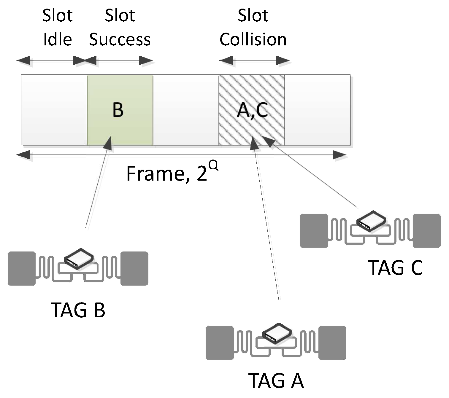
that uniquely identifies a particular tag inside the reader’s range. EPC C1G2 employs a Dynamic Frame Slotted Aloha (DFSA) protocol to arbitrate tags’ collisions, known as the Slot Counter protocol [
9]. It follows a Time Division Multiple Access MAC scheme, scheduling the tags’ responses along time slots (see
Figure 2). The Identification process begins with the reader transmitting a
Query command to set the frame size of value
; then at the end of an old frame set a new frame size, or to jump from one slot to another. Then, tags randomly select a slot in the frame (the initial value of their internal slot counter
going from 0 to
) and respond to the reader when
. Waiting tags decrease their counter every time the reader transmits a
Query command to jump to the next slot. If tags responses collide, they will have to wait until the next frame to choose another slot and transmit again. The probability of collision is sensitive to the choice of the frame size, whose optimum setting depends on the number of responding tags (unknown for the reader). Thus, when
= 0, the tag transmits a 16-bit random number (
); and once it is acknowledged (
), the tag transmits its unique
code. The Identification phase ends when the reader has received the
from a particular tag. The reader commands flow to identify one tag would be as follows (assuming no collision occurred):
Query-
ACK(RN16).
The Sense phase.
Once a particular tag has been identified in the previous phase, during the Sense phase the reader reads data from its sensor. The Sense phase starts when the reader transmits the Req_RN16(RN16) command, asking the tag for a smaller bit-string (16 bits) named which expires after the reading. This phase ends when the reader has received one sensor data from the tag. The reader commands flow to read one sensor data would be as follows: Req_RN16(RN16)-Read(handle).
Figure 2.
Identification phase of the EPC C1G2 protocol.
Figure 2.
Identification phase of the EPC C1G2 protocol.
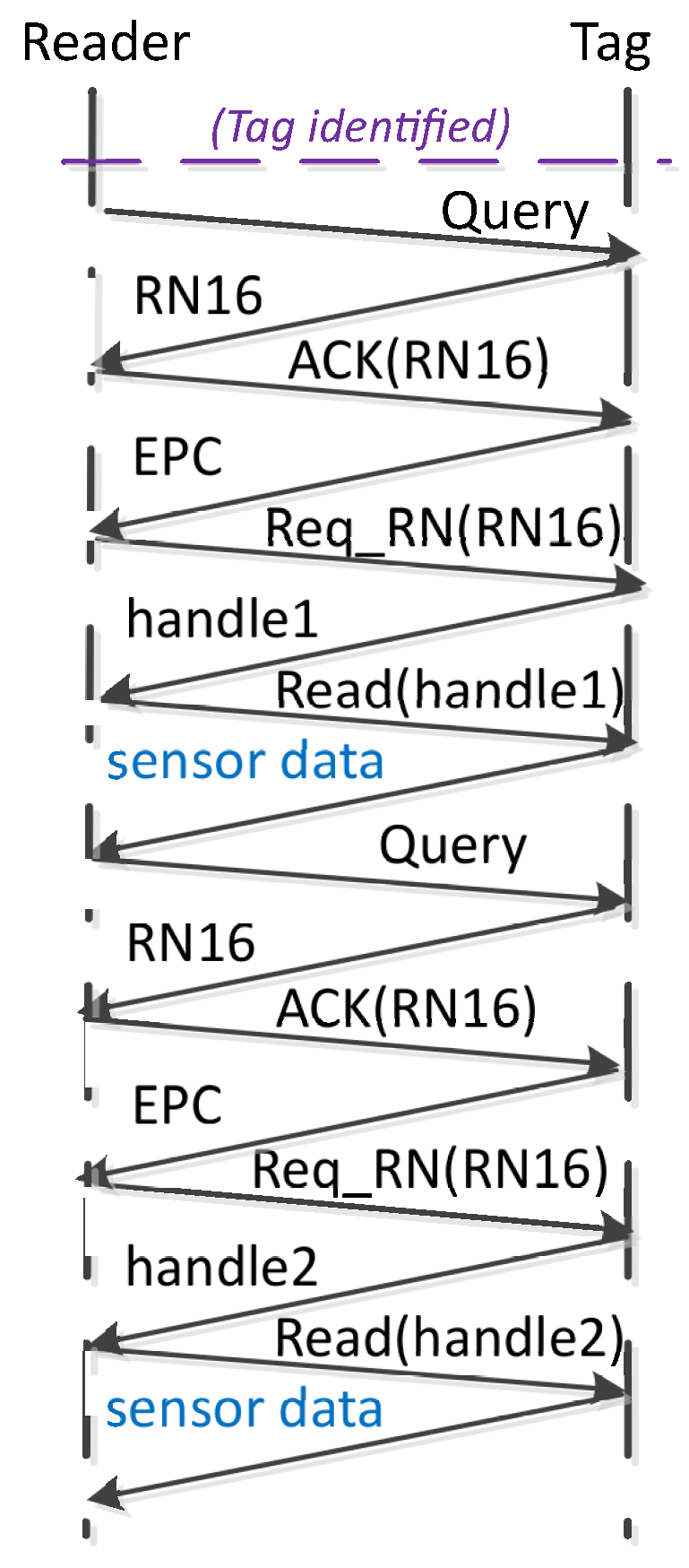
Figure 3 shows an example of the procedure followed by the reader to obtain 2 sensor reads (
) from 2 tags (
), using the standard EPC C1G2. The reader commands flow would be as follows (assuming no collision occurred):
Query-
ACK(RN16)-
Req_RN16(RN16)-
Read(handle 1)-
Query-
ACK(RN16)-
Req_RN16(RN16)-
Read(handle 2).
It can be appreciated that in the standard protocol, the reader must receive the and from a sensor tag before transmitting a Read command to read an additional sensor data. This paper proposes a custom protocol to improve the efficiency of sensors data streaming, by avoiding the overhead caused by having to identify again each sensor tag before reading an additional sensor data.
3. The Proposed Protocol
Using the EPC C1G2, the reader is forced to identify a tag before reading its sensor. This procedure results in a very inefficient strategy of streaming data from sensors. The proposed custom protocol for streaming sensor data provides a much higher reading rate than the protocol used in the current RFID standard. It slightly modifies the Identification phase of the EPC C1G2 extending it until the reception of at least one bit-string of the available tags in the antenna range. Then, the reader would be able to read data from all the sensors by using these previously obtained s.
The proposed protocol employs the interrogation and access commands from EPC C1G2. It is therefore compatible with sensor tags following the EPC C1G2 standard, with the particularity that tags must remember their last transmitted until they loose their state. The presented custom protocol is also separated in two phases: Identification and Sense phase.
Identification Phase
It starts when the reader transmits the first command to identify the N tags inside the reader’s range, and it ends when the reader has received one from each sensor tag or when a timer expires. This timer prevents the reader from remaining in the identification phase for an undesired long time and not reaching the sense phase. At the end of this phase, therefore, the reader ends up with a clear overview of all the tags into its antenna range, their s and s. The reader commands flow to identify one tag would be as follows (assuming no collision occurred): Query-ACK(RN16)-Req_RN16(RN16).
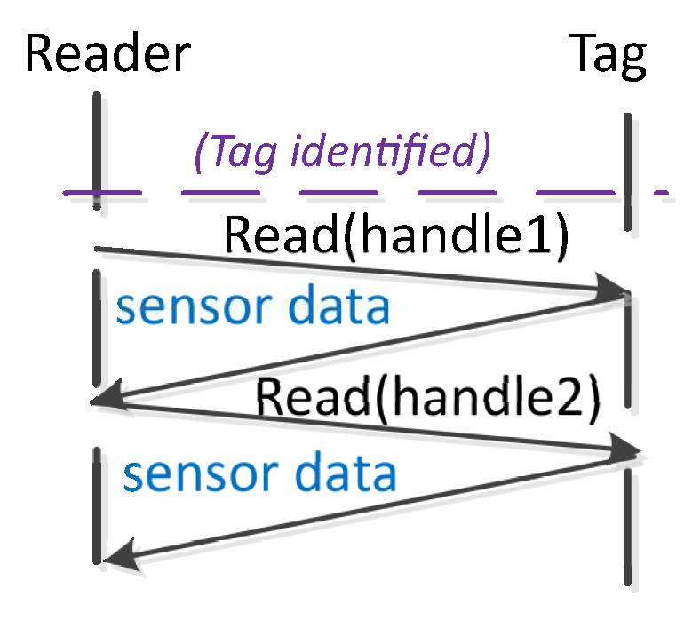
The Sense phase
It starts when the reader transmits the first command. Then, the reader transmits consecutive Read commands to cyclically read one set of data from each sensor. This phase ends when the reader has received the required number of sensor reads S or after a timer expires. This timer prevents the reader from remaining in the sense phase for an undesired long time.
For instance,
Figure 4 assumes
and
, and the Sense phase would consist of the following reader commands flow:
Read(handle 1)-
Read(handle 2)-
Read(handle 1)-
Read(handle 2). This procedure needs the reader to associate these
strings to each
, and the tags to remember their
until the Sensing phase is over.
Figure 4.
Example of the Sense phase with N = 2 and S = 2 for the custom protocol.
Figure 4.
Example of the Sense phase with N = 2 and S = 2 for the custom protocol.
Figure 5 shows a comparison of both the EPC C1G2 procedure and the custom protocol.
It can be appreciated that in the standard EPC C1G2, in order to receive an additional sensor data, the reader must receive the code and one from a sensor tag before transmitting a command. The custom protocol improves the efficiency of sensors data streaming, by avoiding the overhead caused by having to identify again each sensor tag before reading an additional sensor data.
Furthermore, the higher the number of sensor data reads in a dense RFID sensor network, the more notable the improvement of the proposed protocol in terms of in relation to the protocol used in EPC C1G2. In a particular RFID scenario, with a particular set of parameters, if the reader uses the standard protocol, tags’ collisions will affect not only the process of tags identification but also the process of reading the sensors data. Therefore, any additional sensor data read will have a certain probability of tags collisions. In the proposed protocol, collisions only affect the identification phase (assuming that every tag in the system choses a unique ). Once tags are identified, the reader can read consecutive sensor data without experiencing tag collisions.
4. Performance Analysis
To validate the efficiency of the proposed protocol, an RFID sensor network for custom sensor data streaming has been developed with an SDR UHF RFID reader and accelerometer sensors included in WISP tags (version 5.1). The physical system is shown in
Figure 6. The RFID reader consists of a commodity USRP N210, with a single SBX daughter-board, a Gigabit switch, and a Linux laptop. The transmit and receive ports of the daughter-board are connected with two circularly polarized patch antennas of 6dBi gain. All processing of the backscattered signal is performed on a laptop that controls the SDR. The WISP tags have been reconfigured to keep in memory their last transmitted
until they loose their state. Each accelerometer sensor data consists of 32 bits organized in 16-bit words (a total of 2 words). Therefore, in order to request one accelerometer sensor data from a WISP tag, the reader configures the Read command with the field
Word-count: {00000010}. These tags take the data from their accelerometer sensor and save it on memory with a periodic update.
The reader uses the software modules of the system presented in [
10], built on GNU radio 3.7.11 (source, matched filter, gate, decoder, and reader), with extended functionalities, highlighting the differentiation of idle and collision/success tags responses, anti-collision capabilities, and the implementation of additional reader commands.
The SDR reader employs FM0 with
= 12.5
for the commands transmissions, and it has been configured to decode WISP data transmitted with a backscatter-link-frequency,
, of 160 Khz. The reader transmission frequency is set to 915 MHz. An example of the Sense phase of the custom protocol for three different WISP accelerometer tags using the custom protocol is showed in
Figure 7. This figure shows one accelerometer sensor read for each one of the three tags.
Next, the
is evaluated for the proposed custom protocol and the standard protocol for
N = {1, 2, 3} and
S = 5. All the WISP accelerometer tags were placed inside the reader’s range, 1 m away from the antennas. To evaluate
experimentally, a timer is started in the reader program when the reader transmits the first Query, and it is stopped when the reader decodes correctly at least five data packets from each accelerometer tag. Therefore, the experimental results also include the reader processing time. Additionally,
is evaluated analytically by measuring the number of transmitted reader queries (
Query, ACK, Req_RN, Read), and received tag responses (
RN16, EPC, handle, sensor data), and multiplying them by their corresponding duration, which the reader knows a priori. Results are shown in
Figure 8.
Clearly, the proposed custom protocol achieves a higher than the standard protocol, for the three set of tags analyzed. For both protocols, decreases with increasing N, due to tag collisions. Also, experimental is lower than the theoretical one, as expected, because the system requires some time for the processing and calculations tasks. The proposed protocol achieves an improvement in of 74%, 54%, and 53% with respect to the standard for N = 1, N = 2, and N = 3, respectively.
4.1. Identified Limitations
The proposed protocol takes advantage of storing the tag produced after receiving the unique to cyclically read a particular tag. The has a usual length of 128 bits, and the length of the is 16 bits. The total number of distinguishable tags with the is highly superior than with the code ( tags tags). Thus, the probability of assigning the same to 2 different tags is higher. It is, thus, affordable to use a fixed in a local RFID sensor network since the probability of having 2 tags under the same is very small. Nevertheless, in case that could happen, if the reader receives a collided response while reading the tags, it will execute the identification phase again to solve that issue.
The is designed to uniquely identify all the tags in the world, whilst the is only used to differentiate the sensors in a local sensor network, usually, with less than 50 sensors in the worst case. The proposed custom protocol has been designed to stream data from a real/physical RFID sensor network. This involves a reader interrogating and reading a feasible number of 10–15 sensor tags. Of course it does not mean that the custom protocol is not able to read a higher number, quite the opposite. The reader is able to do it, however, it may encounter reading problems, caused by the lack of reading transmitting power of the system used in the experimentation.


