Artificial Landmarks for Autonomous Vehicles Based on Magnetic Sensors †


Abstract
:1. Introduction
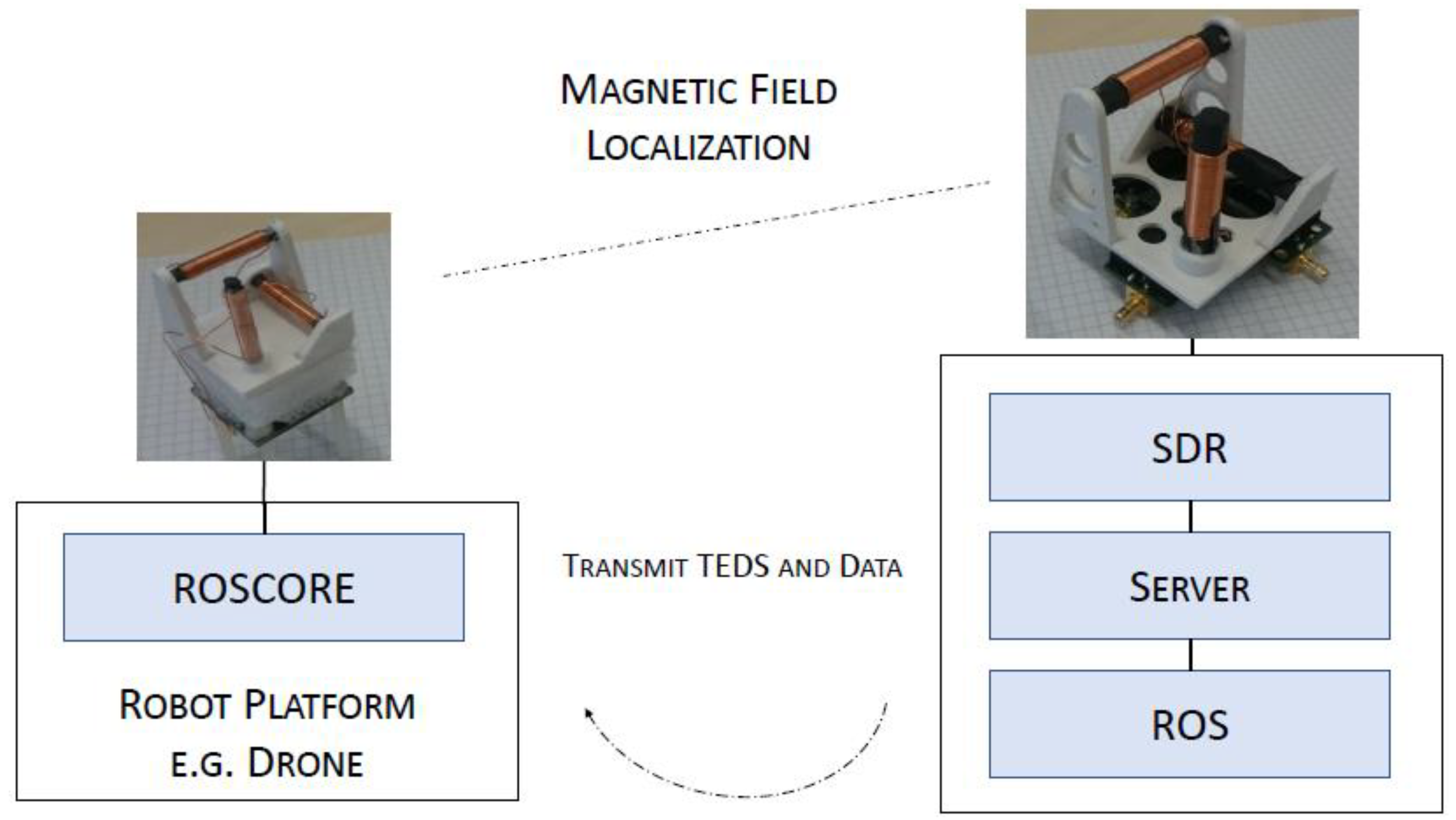
2. Architecture
2.1. Transducer Electronic Data Sheet (TEDS)
2.2. Software Architecture
2.3. Hardware Architecture
3. Conclusions
Acknowledgments
Conflicts of Interest
References
- Weiss, S.; Achtelik, M.W.; Lynen, S.; Chli, M.; Siegwart, R. Real-time onboard visual-inertial state estimation and self-calibration of MAVs in unknown environments. In Proceedings of the 2012 IEEE International Conference on Robotics and Automation, Saint Paul, MN, USA, 14–18 May 2012; pp. 957–964. [Google Scholar] [CrossRef]
- IEEE Standard for a Smart Transducer Interface for Sensors and Actuators–Common Functions, Communication Protocols, and Transducer Electronic Data Sheet (TEDS) Formats; IEEE Std 1451.0-2007; IEEE: Piscataway, NJ, USA, 2007; pp. 1–335. [CrossRef]
- Huang, Z.; Zhu, J.; Yang, L.; Xue, B.; Wu, J.; Zhao, Z. Accurate 3-D Position and Orientation Method for Indoor Mobile Robot Navigation Based on Photoelectric Scanning. IEEE Trans. Instrum. Meas. 2015, 64, 2518–2529. [Google Scholar] [CrossRef]
- Nazemzadeh, P.; Fontanelli, D.; Macii, D.; Palopoli, L. Indoor Localization of Mobile Robots Through QR Code Detection and Dead Reckoning Data Fusion. IEEE/ASME Trans. Mechatron. 2017, 22, 2588–2599. [Google Scholar] [CrossRef]
- Yu, T.; Shen, Y. Asymptotic Performance Analysis for Landmark Learning in Indoor Localization. IEEE Commun. Lett. 2018, 22, 740–743. [Google Scholar] [CrossRef]
- Song, S.; Li, B.; Qiao, W.; Hu, C.; Ren, H.; Yu, H.; Zhang, Q.; Meng, M.Q.H.; Xu, G. 6-D Magnetic Localization and Orientation Method for an Annular Magnet Based on a Closed-Form Analytical Model. IEEE Trans. Magn. 2014, 50, 1–11. [Google Scholar] [CrossRef]
- Gietler, H.; Böhm, C.; Mitterer, T.; Faller, L.M.; Weiss, S.; Zangl, H. 4-DOF Magnetic Field Based Localization for UAV Navigation. In Proceedings of the 2018 International Symposium on Experimental Robotics, Buenos Aires, Argentina, 5–8 November 2018. [Google Scholar]
- Faller, L.M.; Mitterer, T.; Leitzke, J.P.; Zangl, H. Design and Evaluation of a Fast, High-Resolution Sensor Evaluation Platform Applied to MEMS Position Sensing. IEEE Trans. Instrum. Meas. 2018, 67, 1014–1027. [Google Scholar] [CrossRef]
- Lynen, S.; Achtelik, M.W.; Weiss, S.; Chli, M.; Siegwart, R. A robust and modular multi-sensor fusion approach applied to MAV navigation. In Proceedings of the 2013 IEEE/RSJ International Conference on Intelligent Robots and Systems, Tokyo, Japan, 3–7 November 2013; pp. 3923–3929. [Google Scholar] [CrossRef]
- Woodman, O.J. An Introduction to Inertial Navigation; Technical Report; University of Cambridge Computer Laboratory: Cambridge, UK, 2007. [Google Scholar]

Publisher’s Note: MDPI stays neutral with regard to jurisdictional claims in published maps and institutional affiliations. |
© 2018 by the authors. Licensee MDPI, Basel, Switzerland. This article is an open access article distributed under the terms and conditions of the Creative Commons Attribution (CC BY) license (https://creativecommons.org/licenses/by/4.0/).
Share and Cite
Mitterer, T.; Gietler, H.; Faller, L.-M.; Zangl, H. Artificial Landmarks for Autonomous Vehicles Based on Magnetic Sensors. Proceedings 2018, 2, 856. https://doi.org/10.3390/proceedings2130856
Mitterer T, Gietler H, Faller L-M, Zangl H. Artificial Landmarks for Autonomous Vehicles Based on Magnetic Sensors. Proceedings. 2018; 2(13):856. https://doi.org/10.3390/proceedings2130856
Chicago/Turabian StyleMitterer, Tobias, Harald Gietler, Lisa-Marie Faller, and Hubert Zangl. 2018. "Artificial Landmarks for Autonomous Vehicles Based on Magnetic Sensors" Proceedings 2, no. 13: 856. https://doi.org/10.3390/proceedings2130856
APA StyleMitterer, T., Gietler, H., Faller, L.-M., & Zangl, H. (2018). Artificial Landmarks for Autonomous Vehicles Based on Magnetic Sensors. Proceedings, 2(13), 856. https://doi.org/10.3390/proceedings2130856