Proceeding Paper

Gas-Flow Sensor Based on Self-Oscillating and Self-Sensing Cantilever †

1
Department of Micro- and Nanoelectronic Systems, Ilmenau University of Technology, Gustav-Kirchhoff-Str.1, 98693 Ilmenau, Germany
2
Electronic & Sensors, Am Vogelherd 10 (Tor 1), 98693 Ilmenau, Germany
3
ETG Entwicklungs-und Technologie Gesellschaft mbH, Am Eichicht 1 A, 98693 Ilmenau, Germany
*
Author to whom correspondence should be addressed.
Presented at the Eurosensors 2018 Conference, Graz, Austria, 9–12 September 2018.
Proceedings 2018, 2(13), 846; https://doi.org/10.3390/proceedings2130846
Published: 3 December 2018
(This article belongs to the Proceedings of EUROSENSORS 2018)

Abstract

:
In this work the application of a self-sensing and self-actuating cantilever for gas-flow measurement is investigated. The cantilever placed in the flow is excited permanently at its first resonance mode. Simultaneously the resonance amplitude, the resonance frequency and the static bending of the cantilever are detected. All three sizes are related to the velocity of the gas-flow.

Published: 3 December 2018

1. Introduction

Flow sensors are widely used in industry, laboratories, medicine and home. Frequently used mass flow measurement principles are based on thermal conductivity of the gas, float-style, Coriolis force, vortex shedding and differential pressure. Flow sensors based on micro-cantilevers have already been presented in literature [1,2] where a cantilever projecting into a flow stream bents or is vibrated by the flow.
Micro- and nano-cantilevers used among as probes in atomic force microscopy are capable to detect smallest forces [3]. In this patent pending work, these highly sensitive cantilevers with integrated actuator und piezo-resistive read-out were used to measure the gas-flow. This cantilever type allows the flow to be measured simultaneously in two ways with a single sensor. The cantilever is placed in a flow channel, perpendicular to the flow direction and is excited in resonance vibration. Firstly, the cantilever is bent by the flow forces (here called - static operating mode) and secondly its resonance behavior is changed (dynamic operating mode). In the static operating mode, the bending is proportional to the square of the gas-flow velocity. In dynamic operating mode, the resonance amplitude is attenuated with increasing flow velocity and the resonance frequency is slightly shifted to higher values.

2. Experimental Setup and Behavior Description

For the investigations, cantilevers with rectangular cross-section (length l = 350 μm, width w = 140 μm and thickness d = 5 μm) are used (Figure 1). The cantilever has a thermo-mechanical actuator. It is based on a two-layer structure with different thermal expansion coefficients, the silicon beam and an aluminum meander. The aluminum meander also serves as a heating resistor. The emitted heat changes the temperature of the cantilever and its bending. A periodic heating voltage causes the cantilever to oscillate. At the clamping point of the cantilever a Wheatstone bridge of four piezo-resistors is positioned. It serves to detect the deflection of the cantilever.
The cantilever is placed perpendicular to the gas-flow direction in a circular channel. By means of commercial mass flow controllers defined flow rates of different gases (in this work: air and CO2) are set. The dynamic excitation of the cantilever takes place via a DDS (direct digital synthesis) generator and the resulting cantilever oscillation is detected frequency sensitive with a look-in amplifier. Because of the resonance frequency shift due to the gas-flow, a PLL (phase locked loop) was used to ensure that the cantilever permanently oscillates at the resonance point. Resonance amplitude and resonance frequency are detected. Parallel to this, the static deflection of the cantilever is measured.
The cantilever behavior with respect to external force can be described by the differential equation of the simple harmonic oscillator:
m e f f · d 2 x d t 2 + D · d x d t + k · x = F ( t )
with meff—the effective mass, x—the deflection, t—the time, D—the damping, k—the spring constant and F—the external forces. In the case of a periodic force the oscillation amplitude is defined as
x ^ ( ω ) = F ^ / m e f f ( ω 0 2 ω 2 ) 2 + ( D m e f f ω ) 2
with ω 0 = 2 π f 0 = k m e f f —resonance frequency and ω—the excitation frequency. The resonance amplitude is significantly dependent on the damping:
x ^ m a x = F ^ / m e f f ω 0 2 · ω 0 D m e f f · 1 1 ( D m e f f 2   ω 0 ) 2 F ^ / m e f f ω 0 2 · ω 0 D m e f f F ^ / m e f f ω 0 2 · Q   .
In this manner we can determine the quality factor Q at the resonance of the cantilever. Under the action of a constant force, Hooke’s law follows:
k · x = F
In addition, for the description of the movement of the cantilever in a gas atmosphere under normal pressure (1013 mbar), it is assumed that the gas can be regarded as a viscous liquid.
First, we are considering a non-oscillating cantilever placed in the gas stream. It is deflected by the drag force. The cantilever deflection 𝑥0 depends on the velocity 𝑣0 according to
  k · x 0 = F D = 1 2 · ρ g a s · w · l · C D · | v 0 | · v 0   .
The drag coefficient 𝐶𝐷 depends on the geometry of the body and the flow conditions, quantified by the Reynolds number
R e =   ρ g a s · w · v 0   η g a s
with 𝜌𝑔𝑎𝑠—the gas density, 𝜂𝑔𝑎𝑠—the dynamic viscosity of the gas and w—the cantilever width. For the output signal of the sensor (voltage of the Wheatstone bridge) follows
u s t a t ~ x 0 ~ v 0 2   .
It should be noted that for low Reynolds numbers, i.e., for small flow velocities the drag coefficient changes relatively strongly with the flow velocity, which consequently means a deviation from the quadratic dependence in this range.
Now, if the cantilever is excited at resonance, the movement of the cantilever overlaps with the gas-flow. For the force acting on a resonating cantilever (ω0,gas—the resonance frequency in gas) follows
F D = 1 2 · ρ g a s · w · l · C D · | v 0 x ^ · ω 0 · sin ( ω 0 , gas t ) | · ( v 0 x ^ · ω 0 , gas · sin ( ω 0 .gas ) )   .
Assuming that the cantilever velocity is small compared to the flow velocity (this is true for a wide range of applications: v 0 = 0 , 5..30 m / s , x ^ · ω 0 , gas 0 , 05 m / s ), one obtains
F D   1 2 ρ g a s   w l C D | v 0 | v 0 ρ g a s w l C D | v 0 | x ^ ω 0 , gas sin ( ω 0 , g a s t )   1 2 ρ g a s w l C D | v 0 | v 0 D v   x ^ ω 0 , gas sin ( ω 0 , g a s t )   .
The 1st term describes the flow force that causes the static bending of the cantilever (see Equation (5)), and the second term the force that counteracts the vibration movement, i.e., that damps the oscillation.
This damping increases with increasing flow velocity
D v = ρ g a s w l C D | v 0 |
and leads to a decrease in the oscillation amplitude. The amplitude of the periodic part of the sensor signal shows the following relationship
u ^ m a x ~ x ^ m a x ~ 1 D v ~ 1 | v 0 |   .
Since the damping of the oscillation of a cantilever does not disappear in the quiescent gas, this proportion must be taken into account. It was examined for a quiescent fluid in [4,5,6]. The following relationship for viscous damping was given by Maali et al. [6]:
D 0   π 4 · ρ g a s · w 2 · l · ω 0 , gas · { 3 , 8018 · δ w + 2 , 7364 · ( δ w ) 2 } = π 2 ·   η g a s · l · { 3 , 8018 · w δ + 2 , 7364 }
the cantilever, 𝑙—the length of the cantilever, 𝜌𝑔𝑎𝑠 - the density of the gas and 𝜂𝑔𝑎𝑠 the dynamic viscosity of the gas. The 1st term describes the influence of movement of the cantilever on the damping, it increases with decreasing viscous layer thickness δ, which gets smaller with rising frequency ω0.gas, and the second term is the so-called Stokes’ term. This means that the damping of the oscillating cantilever is determined by Equation (12) for small flow velocities and satisfies the dependence of (10) for larger velocities. A simple approach is to add both parts together
D = D 0 + D 𝑣
Furthermore, according to [6], the amount of gas co-moved by the oscillating cantilever causes a reduction of the resonance frequency in respect to the resonance frequency in vacuum
ω 0 , vac ω 0 , gas 1 + ρ g a s · π · w 4 · ρ · d · [ 1,0553 + 3,7997 δ w ]   .
At higher resonance frequencies, a small decrease in this influence occurs due to the thickness reduction of the viscous boundary layer δ. The gas-flow also influences this boundary layer around the cantilever.

3. Results

The responds of the cantilever sensor in respect to the gas-flow through a channel with a diameter of 1 mm is shown in Figure 2 for air and CO2. All 3 measured variables - the resonance amplitude, the resonance frequency and the static deflection – are changed due to the gas-flow:
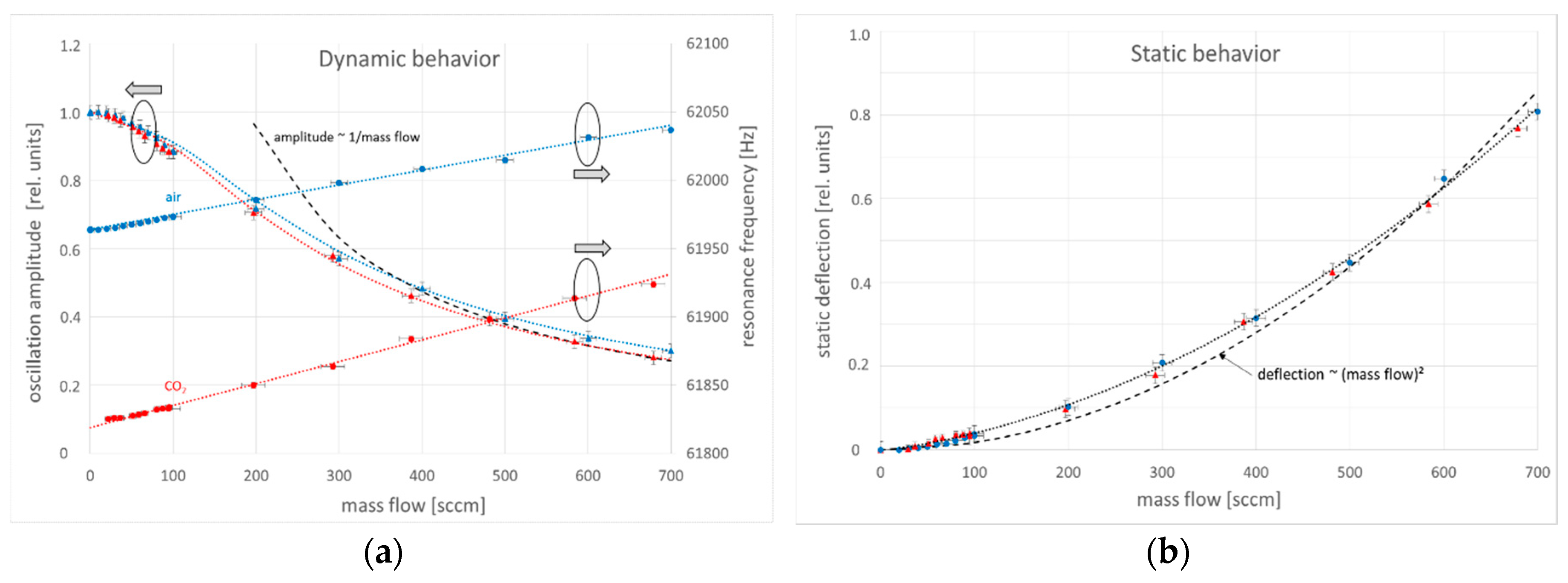
  • The static deflection increases quadratically with the flow velocity according to equation (5). In the lower flow range, the measurement is inaccurate due to the very small responds and the noise of the static measurement.
  • The resonance amplitude drops with 1/v. It has a high sensitivity in the flow range of 1–10 m/s. In this range it decreases by 50%.
  • The resonance frequency increases linearly with the flow velocity. The change is small: Δ f 0 / f 0 Δ ν 0 0 , 1 0 , 2   % / m s . The size of the resonance frequency and its change as a function of the gas-flow is gas type dependent.
A combination of both methods offers an extension of the measuring range and accuracy, as well the gas type determination.

Author Contributions

J.-P.Z., I.W.R. and S.D. conceived and designed the experiments; J.-P.Z., J.S. and S.D. performed the experiments and analyzed the data; T.I. and M.H. designed and fabricated the cantilever; W.E. developed the electronic; W.U.R. constructed and built the sensor enclosure; J.-P.Z. wrote the paper.

Funding

This research was funded by the federal state of Thuringia and the European Community (European Regional Development Fund—ERDF 2014–2020, Project-Nr. 2017VF0047). The APC was funded by the University of Technology Ilmenau.

Conflicts of Interest

The authors declare no conflict of interests.

References

  1. Zhang, S.; Lou, L.; Park, W.-T.; Lee, C. Characterization of a silicon nanowire-based cantilever air-flow sensor. J. Micromech. Microeng. 2012, 22, 095008. [Google Scholar] [CrossRef]
  2. Ju, P.-Y.; Tsai, C.-H.; Fu, L.-M.; Lin, C.-H. Microfluidic flow meter and Viscometer utilizing flow-induced Vibration on an optic fiber cantilever. Transducers 2011, 11, 1428–1431. [Google Scholar]
  3. Rangelow, I.W.; Ivanov, Tz.; Ahmad, A.; Kästner, M.; Lenk, C.; Bozchalooi, I.S.; Xia, F.; Youcef-Toumi, K.; Holz, M.; Reum, A. Active scanning probes: A versatile toolkit for fast imaging and emerging nanofabrication. J. Vacuum Sci. Technol. B 2017, 35, 06G101. [Google Scholar] [CrossRef]
  4. Hosaka, H.; Itao, K.; Kuroda, S. Damping characteristics of beam-shaped micro-oscillators. Sens. Actuators A Phys. 1995, 49, 87–95. [Google Scholar] [CrossRef]
  5. Sader, J.E. Method for the calibration of atomic force microscope cantilevers. J. Appl. Phys. 1998, 84, 64–76. [Google Scholar] [CrossRef]
  6. Maali, A.; Hurth, C.; Boisgard, R.; Jai, C.; Cohen-Bouhacina, T.; Aime, J.-P. Hydrodynamics of oscillating atomic force microscopy cantilevers in viscous fluids. J. Appl. Phys. 2005, 97, 074907. [Google Scholar] [CrossRef]
Figure 1. (a) Self-actuated cantilever with integrated read-out; (b) gas-flow sensor enclosure with cantilever and preamplifier; (c) diagram of PLL based sensor control with signal separation.
Proceedings 02 00846 g001
Figure 2. (a) Measured dependency of resonance amplitude, resonance frequency and (b) bending of the cantilever sensor on the gas-flow through a tube with 1 mm diameter (dotted line—fitted curve, dashed line—simplified behavior, symbols - measured values, blue—air, red—CO2).
Proceedings 02 00846 g002
Publisher’s Note: MDPI stays neutral with regard to jurisdictional claims in published maps and institutional affiliations.

