Proceeding Paper

Piezoelectric Sensors for Lamb Waves’ Direction of Arrival (DoA) Estimation †

1
Department of Electrical, Electronic and Information Engineering “Guglielmo Marconi”, University of Bologna, 40123 Bologna, Italy
2
Center for Industrial Research on Information and Communication Technologies (CIRI ICT), University of Bologna, 40123 Bologna, Italy
3
ARCES Research center, University of Bologna, 40123 Bologna, Italy
*
Author to whom correspondence should be addressed.
Presented at the Eurosensors 2018 Conference, Graz, Austria, 9–12 September 2018.
Proceedings 2018, 2(13), 806; https://doi.org/10.3390/proceedings2130806
Published: 22 November 2018
(This article belongs to the Proceedings of EUROSENSORS 2018)

Abstract

:
A novel strategy to design piezoelectric sensor clusters suited for direction of arrival (DoA) estimation of Lamb waves is presented in this work. The designed clusters are composed by three piezoelectric patches (P1, P2 e P3) to be bonded on the structure to be inspected. In particular, by exploiting the Radon Transform, the proposed sensor design procedure computes the shape of P2 given the shape of P1 so that the difference in time of arrival (DToA) of the Lamb waves at the two patches is linearly related to the DoA. Such properties allow to minimize the DoA uncertainty. The sensor P3 is designed to perform the estimation of DoA without knowing the actual wave velocity. Numerical results show that DoA is extremely robust.

1. Introduction

Recent research efforts are aimed at the development of Structural Health Monitoring (SHM) systems. In particular, passive SHM methods are driven by the need to monitor anomalous acoustic events, such as those generated by an impact, by using piezoelectric sensors. When an impact is detected, it is important to locate the impact point. However, the actual approaches for impact localization are either onerous from the computational point of view, or based on a large number of sensors. Cluster of sensors can be used for the estimation of DoA. By using two sensor clusters, it is possible to estimate the impact location via triangulation procedures. In this work, a novel cluster based on shaped piezosensors is designed with the aim of minimizing the number of sensors per monitored area and the uncertainty in the DoA estimation which can be performed without knowing the waveguide geometrical and mechanical properties (dispersion curves).
The proposed sensor design strategy is based on the Radon Transform and its Inverse. The approach accuracy was evaluated numerically by estimating the DoA of the fundamental antisymmetric and symmetric modes (A0 and S0), propagating in an aluminum plate.

2. Propagation of Uncertainty in DoA Estimation

Sensor clusters commonly used in literature for DoA estimation consist of couples of circular piezo, e.g., the piezopatches P1 and P2 [1]. Assuming a planar wavefront, the DToA (Δt) is related to the wave DoA (θ) by this formula:
Δ t ( θ ) = d cos θ v
where d is the distance among the sensors and v is wave velocity. Consequently, we can evaluate the DoA as:
θ e s t = arccos v Δ t e s t d
by measuring the DToA, i.e. Δtest. By exploiting the Propagation of Uncertainty theory, it is possible to observe that, due to the arccos relation, the error in the estimation can be very large for low values of θ. In [2], it was shown that when a linear dependence between the DToA and the DoA is achieved by properly reshaping the sensors so that:
Δ t ( θ ) = α θ v + Δ t ( 0 )
then the worst-case error is constant over the considered range of angles (θ ∈ [0°,90°]), and considerably lower than the error achieved by using the conventional sensors.
It is worth noting that since the sensors are shaped differently, they generally have different frequency responses. This may hamper the possibility of using the DToA estimation method based on the tracking of the peak of the cross-correlation envelope, which is the optimal method in noise-affected measurements. In the next section, we will summarize the method presented in [1] to achieve equal frequency amplitude responses and a linear dependence between DToA and DoA.

3. The Radon Transform as Sensor Design Tool

To achieve the desired goals it is necessary to investigate the frequency response of a generic sensor impinged by a Lamb wave. According to formulation presented in [3], the voltage VP(ω) generated by sensor of arbitrary shape ΩP(x, y) in presence of a plane Lamb wave propagating at angle θ can be expressed as:
V P ( ω ) = j U ( ω ) k 0 ( ω ) H ( θ ) D P ( ω , θ )
A detailed analysis of functions U(ω), k0(ω) and H(θ) can be found in [3]. DP(ω,θ) is the sensor directivity function which can be computed by the following integral:
D P ( ω , θ ) = Ω P e j k 0 ( ω ) ( x cos θ + y sin θ ) ϕ P ( x , y ) d x d y
where ϕP(x, y) is referred to as shape function. ϕP(x, y) is a step function which is equal to 1 if the point of coordinates (x, y) belongs to the area of the piezoelectric patch ΩP, and 0 elsewhere.
Two different sensors placed on the same specimen and hit by the same wave may have different frequency responses VP1(ω) e VP2(ω) if the directivity functions DP1(ω,θ) and DP2(ω,θ) are different. Whereas if the directivity functions are equal, a part from a linear phase-factor in θ, i.e., Proceedings 02 00806 i001, and in case of a non-dispersive propagation, i.e., k0(ω) = ω/vg, we have that:
(1).
The frequency responses VP1(ω) e VP2(ω) are equal a part from a scaling factor and a linear phase-shift in θ. Then, it is possible to use the cross-correlation method for estimating the DoA.
(2).
Antitransforming according to Fourier, vP1(t) e vP2(t) are equal except for a scale factor and a linear time-shift in θ, obtaining the desired target: Δt = (ρ0 + αθ)/vg.

Sensor Directivity Analysis and Synthesis

From Equation (5) follows that DP(ω,θ) can be computed from the coefficients in the direction θ of a bidimensional (spatial) Fourier transform (FT) of φP(x, y). It is worth noting that the Projection-slice theorem [4] states that the bidimensional FT of the initial function along a line at inclination angle θ is equal to the mono-dimensional FT of the Radon transform (acquired at angle θ) of that function. The Radon transform at angle θ of a generic shape function ϕ(x, y) defined in domain Ω can be computed by using the following formula:
R θ ( ρ ) [ ϕ ( x , y ) ] = ϕ ( x , y ) δ ( ρ x cos θ y sin θ ) d x d y
and consists of multiple line-integrals.
From Equation (5) and the Projection-slice theorem we can conclude immediately that if two piezoelectric patches ϕ1 and ϕ2 have the same Radon transform along a given direction θ apart from a linear spatial-shift in θ, i.e., Rθ(ρ)[ϕ2] = Rθ(ρρ0αθ)[ϕ1], their directivity functions DP1 and DP2 differs only by a phase shift which is directly related to the spatial shift, i.e., Proceedings 02 00806 i002. The shape synthesis procedure exploits the fact that the Radon transform can be inverted with suitable algorithms. Then, defined the geometry of the piezo patch P1 (ϕ1(x, y)) (e.g., a conventional disk), computed the Radon transform R1θ(ρ) of the shape ϕ1(x, y), the desired Radon transform of the shape ϕ2(x, y) is
R 2 θ ( ρ ) = R 1 θ ( ρ ρ 0 α θ )
Through the inverse Radon transform (IRT) of R2θ(ρ) it is possible to obtain ϕ 2 ( x , y ) Applying a binary quantization procedure, it is possible to transform ϕ 2 ( x , y )  in the desired step function of P2, ϕ2(x, y). It is worth noting that the sensor design strategy just presented is not based on the knowledge of the waveguide geometrical and mechanical properties (dispersion curves) but it is still necessary to know the group velocity for the estimation of θ. Then, a third sensor (P3) must be designed in order to estimate the group velocity. To this aim, we impose that the directivity functions DP1(ω,θ) and DP3(ω,θ) are equal a part from a constant phase shift in θ, i.e., Proceedings 02 00806 i003
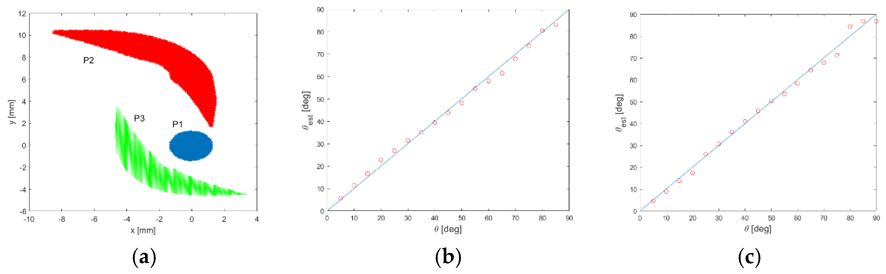
. In this way, in case of non-dispersive propagation, i.e., k0(ω) = ω/vg, vP1(t) and vP3(t) are shifted by a constant Δt13 = ρ3/vg. This relation clearly highlights how to estimate vg from Δt13. To obtain the aforementioned relationship between the directivity functions, it is sufficient to impose a relation between the Radon transforms of the shape functions ϕ1 and ϕ3 as follows:
R θ ( ρ ) [ ϕ 3 ] = R θ ( ρ ρ 3 ) [ ϕ 1 ]
Then the steps of shape synthesis procedure are the same as those shown to obtain ϕ2(x, y).

4. Numerical Validation

To validate the proposed sensor technology, multiple impacts occurring on an aluminum plate 3 mm of thick were simulated. The response of a shaped piezo-patch to impacts generating the fundamental antisymmetric and symmetric mode (A0 and S0) was computed using the Green’s function formalism adopted in [2]. The sensors P1, P2 and P3 are represented in Figure 1a.
The DToA between P1 and P2 and the one between the P1 and P3 were computed by applying a cross-correlation procedure and their ratio Δt12 and Δt13 was used to estimate DoA (θ). The linear regression procedure was used to estimate DoA in the presence of the A0 mode. The calibration curve thus obtained was proven to be effective even when the S0 mode propagation was simulated.
The estimated DoA (θest) is represented in Figure 1b,c as a function of its actual value (i.e., θ). The standard deviation of |θestθ| is below 1.4 degrees in both cases.

5. Conclusions

In this work, a novel procedure to design piezoelectric sensors for Lamb waves direction of arrival (DoA) estimation is proposed. The designed cluster is composed by three sensors. The first one can be conventionally shaped (as a disk). The second and third sensors are derived from the first one with a procedure which is based on the direct and inverse Radon transform. This method is conceived so that a linear dependence is imposed between the difference in time of arrival (DToA, Δt12) of the wavefront at P1 and P2 sensors and the direction of arrival (DoA, θ) of the wavefront itself, minimizing the uncertainty in the DoA estimation. Furthermore, it is possible to use the cross-correlation procedure to estimate Δt12 and θ. The third sensor P3 is designed to estimate the group velocity, necessary for DoA (θ) estimation. A numerical validation shows excellent performances of the designed cluster in the estimation of the DoA.

References

  1. Kundu, T.; Das, S.; Jata, K. Detection of the point of impact on a stiffened plate by the acoustic emission technique. Smart Mater. Struct. 2009, 18, 035006. [Google Scholar] [CrossRef]
  2. De Marchi, L.; Testoni, N.; Marzani, A. Spiral-shaped piezoelectric sensors for Lamb waves direction of arrival (DoA) estimation. Smart Mater. Struct. 2018, 27, 045016. [Google Scholar] [CrossRef]
  3. Senesi, M.; Ruzzene, M. A frequency selective acoustic transducer for directional lamb wave sensing. J. Acoust. Soc. Am. 2011, 130, 1899–1907. [Google Scholar] [CrossRef] [PubMed]
  4. Gaskill, J.D. Linear Systems, Fourier Transforms, and Optics; Wiley: New York, NY, USA, 1978. [Google Scholar]
Figure 1. (a) Designed sensors: P1 (blue disk), P2 (red) and P3 (green). (b,c) Estimated DoA (θest) with respect to the actual DoA (θ) with respectively A0 and S0 in propagation.
Proceedings 02 00806 g001
Publisher’s Note: MDPI stays neutral with regard to jurisdictional claims in published maps and institutional affiliations.

