Abstract
A mathematical model is developed to describe the 2𝜃 in-plane flexural response of supported ring-based Coriolis Vibrating Gyroscopes (CVGs) as the ring is driven into large amplitude vibration. Whilst the 2𝜃 degenerate modes have same resonance frequency in the linear regime, mechanical non-linearity within the support structure induces a frequency split as the vibration amplitude increases. The origins and effects of geometrical non-linearity are investigated using the proposed analytical model.
1. Introduction
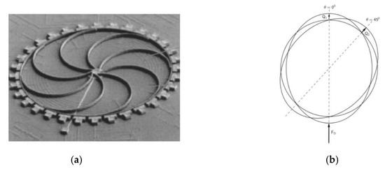
Micro-Electro-Mechanical Systems (MEMS) ring-based Coriolis Vibrating Gyroscopes (CVGs) are used to measure angular velocity in a large variety of aerospace and automotive applications [1]. Figure 1 shows a typical configuration for these devices, where the ring is the vibrating element, supported by spokes which are anchored to a fixed frame. For devices operating using 2𝜃 in-plane flexural response, 8 support legs are commonly used to maintain the symmetry.

Figure 1.
(a) Typical configuration for ring-based CVG having 8 support spokes [3]; (b) For devices operating using 2𝜃 in-plane flexural responses, the drive mode is excited at resonance by applying a harmonic drive force; rotation about the ring polar axis induces the sense mode to vibrate, aligned 45 degrees to the drive mode.
Normally, the primary 2𝜃 mode (or drive mode) is driven into resonance by applying a harmonic drive force. Coriolis forces due to rotation of the ring around its polar axis excite secondary 2𝜃 mode (or sense mode) vibrations that are proportional to the angular velocity experienced by the sensor [2]. Drive and sense 2𝜃 modes have the same shape but are oriented 45 degrees from each other as shown in Figure 1.
In the linear regime, supports exert restoring forces on the ring which are proportional to ring displacements, and having 8 support legs ensures the drive and sense resonance frequencies remain the same. To increase the sensitivity of device, it is desirable to excite the drive mode into large amplitude vibration so the sense output is increased. This paper investigates the effect of increasing the drive mode amplitude on the drive and sense frequencies by developing a mathematical model for the resonator including ring non-linear flexural vibration and non-linear support stiffness. This model is used to calculate non-linear frequency backbone curves for the drive and sense 2𝜃 modes as the ring is driven into large amplitude vibration.
2. Mathematical Model
The proposed analytical model is based on using an inextensible curved beam to model the ring and 8 lumped masses and non-linear cubic springs orientated radially and tangentially to the ring to model the support legs [4]. The inertia and non-linear stiffness properties for each support are calculated using a finite element model of a single support spoke. The radial and tangential displacements of the ring centre line are expressed in terms of generalised coordinates 𝑄1(𝑡) and 𝑄2(𝑡) representing the radial anti-nodes responses of the drive and sense 2𝜃 modes, including a breathing mode to take into account non-linear flexural ring vibration [5].
Lagrange’s method is used to obtain the governing equations of motion for generalised coordinates 𝑄1(𝑡) and 𝑄2(𝑡). The drive mode is assumed to be excited into resonance by a harmonic modal force having magnitude 𝐹𝐷 and frequency Ω. Coriolis effects are included in the model to take into account ring rotation around its polar axis at angular velocity Ωz. Non-linear terms in 𝑄2 (including derivatives and combinations of modal contributions) are neglected based on the assumption that the sense response is much smaller than the drive response. Backwards coupling from the sense mode to the drive mode is also neglected, so that the equations of motion for the drive are independent of the sense response.
2.1. Non-linear Unsupported Ring
For an unsupported ring undergoing non-linear flexural vibration, governing equations for the drive and sense modes are:
where 𝜔0𝑟 is the un-damped natural frequency of the 2𝜃 modes of the ring only; 𝜇 the viscous damping coefficient; 𝑀𝑟𝑖𝑛𝑔 ring modal mass; 𝛼, 𝛽 and 𝛾𝑖 are non-linear inertia and stiffness coefficients due to inclusion of the breathing mode representing non-linear flexural vibration of the ring. Comparing Equations (1) and (2) it can be seen that both equations of motion have the exact same form with identical coefficients. A direct consequence of this is that the drive and sense 2𝜃 resonance frequencies of an unsupported ring are equal to each other (no split) in the linear regime (i.e., 𝜔0𝑟) and the non-linear regime as the drive amplitude is increased.
2.2. Supported Ring: Mechanical Non-linearity in Support Structure
Including the support structure, it can be shown that the governing equations for the drive and sense responses become:
where 𝜔0 is the un-damped natural frequency of the 2𝜃 modes, 𝑀𝑟𝑒𝑠 is the resonator modal mass, and 𝛼, 𝛽 and 𝛾𝑖 are non-linear inertia and stiffness coefficients depend upon non-linear ring flexural vibration, mechanical support non-linearity and location of the support leg relative to the drive force. Whilst Equations (3) and (4) have the same form, the non-linear coefficients are not the same, indicating that the drive and sense modes are governed by different equations of motion.
3. Analytical solution method
The Method of Averaging is employed to determine frequency backbone curves for the drive and sense frequencies. As the sense vibration amplitude is assumed small, the drive mode is independent of sense vibration and the drive response can be expressed easily in terms of amplitude and phase relative to the exciting force by averaging Equation (3). The sense response is analysed as a second step by averaging Equation (4) to determine the sense response amplitude and phase relative to the drive response. The frequency response curves (amplitude and phases) are calculated for a set of magnitudes of the excitation.
The frequency backbone curve of drive mode is obtained as the drive frequency which induces a drive response phase of −90 degrees relative to the exciting force. The sense frequency is calculated as the drive excitation frequency which induces a sense response whose phase relative to drive response is −180 degrees, as suggested by Coriolis excitation proportional to in Equation (4).
4. Results
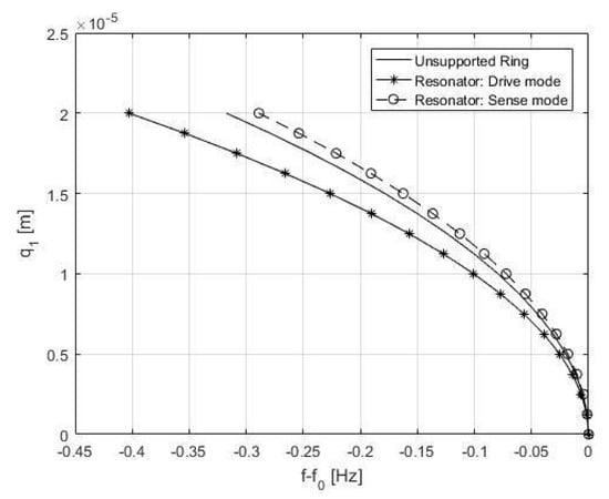
In the following, frequency backbone curves for the example considered by Serandour [4] are presented for (i) an unsupported ring and (ii) the same ring supported by 8 support spokes. Results are calculated for a quality factor of 1000, angular velocity 60 degrees per second and a driving force applied midway between two adjacent support legs. The largest drive amplitude considered is 20 which corresponds to a practical value for a typical MEMS CVG device. Figure 2 shows the shift from linear resonance frequency plotted against averaged drive amplitude.

Figure 2.
Frequency backbone curves for the 2𝜃 modes for (i) an unsupported ring; (ii) a ring supported by 8 support spokes.
For the unsupported ring case, the drive and sense frequencies are equal for all drive amplitudes considered. The non-linear flexural vibration of the ring causes the resonance frequency to decrease as the vibration amplitude increases indicating a softening dynamic behaviour. For the supported ring case, the drive and sense frequencies do not have the same value, except for the linear case when the drive response amplitude is smallest. As the drive mode is driven into large amplitude, the drive and sense frequencies split. The observed frequency split is caused by mechanical support non-linearity included in the model.
Comparing the unsupported and supported cases it can be seen that the drive mode for the supported ring is more softening than unsupported ring, indicating that the support is softening.
5. Conclusions
A mathematical model has been developed to investigate the effect of mechanical non-linearity in ring and support legs on the drive and sense frequencies for a ring-based CVG. Equations of motion governing the 2𝜃 mode responses are developed and the method of averaging used to determine non-linear frequency backbone curves for drive and sense 2𝜃 modes. It is shown that the drive and sense frequencies split when the ring is driven into large amplitude vibration, and that this is caused by mechanical non-linearity in the support structure. It is anticipated that this non-linear frequency splitting has potential to degrade ring based CVG performance in practical devices.
References
- Acar, C.; Shkel, A. MEMS Vibratory Gyroscopes: Structural Approaches to Improve Robustness; Springer: Berlin, Germany, 2008. [Google Scholar]
- Apostolyuk, V. Coriolis Vibratory Gyroscopes: Theory and Design; Springer: Berlin, Germany, 2015. [Google Scholar]
- Xie, H.; Fedder, G.K. Integrated microelectromechanical gyroscopes. J. Aerosp. Eng. 2003, 16, 65–75. [Google Scholar] [CrossRef]
- Serandour, G.; Fox, C.H.J.; McWilliam, S. Modelling geometric nonlinearity in a MEMS resonator. In Proceedings of the IX International Conference on Recent Advances in Structural Dynamics/RASD06, Southampton, UK, 17–19 July 2006. [Google Scholar]
- Evensen, D.A. Non-linear flexural vibrations of thin circular rings. J. Appl. Mech. 1966, 33, 553–560. [Google Scholar] [CrossRef]
Publisher’s Note: MDPI stays neutral with regard to jurisdictional claims in published maps and institutional affiliations. |
© 2018 by the authors. Licensee MDPI, Basel, Switzerland. This article is an open access article distributed under the terms and conditions of the Creative Commons Attribution (CC BY) license (https://creativecommons.org/licenses/by/4.0/).