1. Introduction
Micromachined silicon accelerometers are widely used in automotive applications (safety systems) such as airbag release, seat belt control, active suspension and braking and traction control systems [
1]. MEMS accelerometers’ basic scheme consists of a proof mass and an appropriate sensing system [
2]. The most common acceleration sensing mechanisms are capacitive [
3], piezoresistive [
4], and piezoelectric [
5]. In resonant accelerometers, acceleration is sensed by a change in the resonance frequency and since they are FM, their output signals are generally more immune to noise and can be converted easily into a digital format, reducing the need of complex readout circuits [
2]. The most common effect used for varying the resonator’s resonance frequency is the stress-induced stiffness change. Generally, the resonator can be driven into resonance by electrostatic, piezoelectrical or electrothermal actuation. The resonance frequency can be sensed piezoelectrically, capacitively or piezoresistively.
In the case of automotive applications, the resonance frequency should be much higher than the range of vehicle vibrations (>100 kHz), which is difficult to obtain with capacitive resonators. In addition, a higher resonance frequency enables a higher sensor bandwidth. In this work a differential silicon resonant accelerometer (
Figure 1a) is introduced with a very high resonance frequency (well above the typical frequency range of vehicle vibrations). The high resonance frequency of the accelerometer guarantees high immunity to noise, high stability and a large bandwidth, making it suitable for several automotive applications.
2. Accelerometer Principle of Operation
The sensing mechanism of the accelerometer introduced here is the double-mass resonator shown in
Figure 1b. The mass plates vibrate in-plane and in opposite directions (anti-phase) and they are electrostatically driven at resonance. When the proof mass is subjected to an external acceleration in the sensitive axis (
Figure 1a), the springs sustaining the resonator are axially loaded, changing their acceleration moves the proof mass, the springs of one resonator are under compression while the other resonator springs are under tension. The tensile/compressive axial loading shifts the resonance frequency, the tensile force increasing it and the compressive force decreasing it [
6]. This shift is proportional to and a measure of the external acceleration. The differential design scheme also allows to cancel device thermal mismatches and nonlinearities.
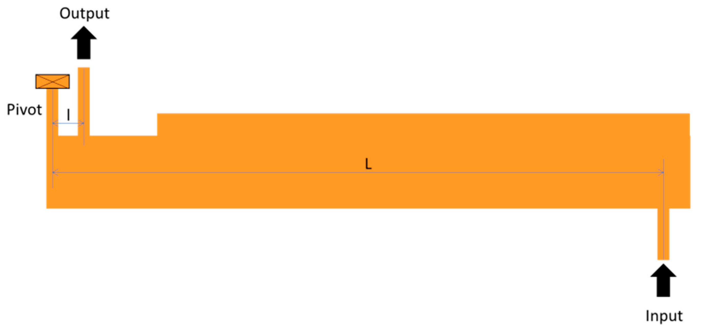
Furthermore, the accelerometer includes a leverage mechanism to amplify the inertial force transmitted by the proof mass to the springs (
Figure 1a). The leverage design is based in the work presented by S. X.-P. Su and H. S. Yang in [
6]. The leverage mechanism is composed by two levers connecting the proof mass to the resonators’ springs. Each lever is composed by a pivot beam acting as a fulcrum; an input and output beams, which transmit the inertial force to the lever and the amplified force to the resonators’ springs, respectively. In practice, the lever amplification factor,
A, is smaller than the ideal
A, which depends on the distance between the input beam and the pivot beam (
L) and the distance between the output beam and the pivot beam (
l), according to
A =
L/
l.
Figure 2 represents a design of the microlever used in this work.
The output signal is measured piezoresistively, using the modulation of the DC bias current in the vibrating connection beam.
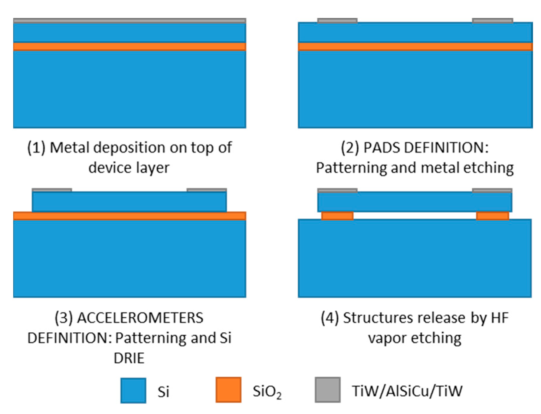
3. Accelerometer Fabrication Steps
The accelerometers were fabricated on an n-doped SOI wafer with a 5 µm thick device layer, using a two-mask fabrication process: one defining the electrical pads and the other defining the structure. First, the metal used for the electrical pads is deposited by sputtering on top of the device layer. This metal film is patterned and etched to open the pads. Then, a new patterning is realized to define the silicon structures. Silicon is etched by deep reactive ion etching (DRIE). Finally, the accelerometers are released by HF vapor etching. These main fabrication steps are illustrated in
Figure 3.
4. Experimental Results
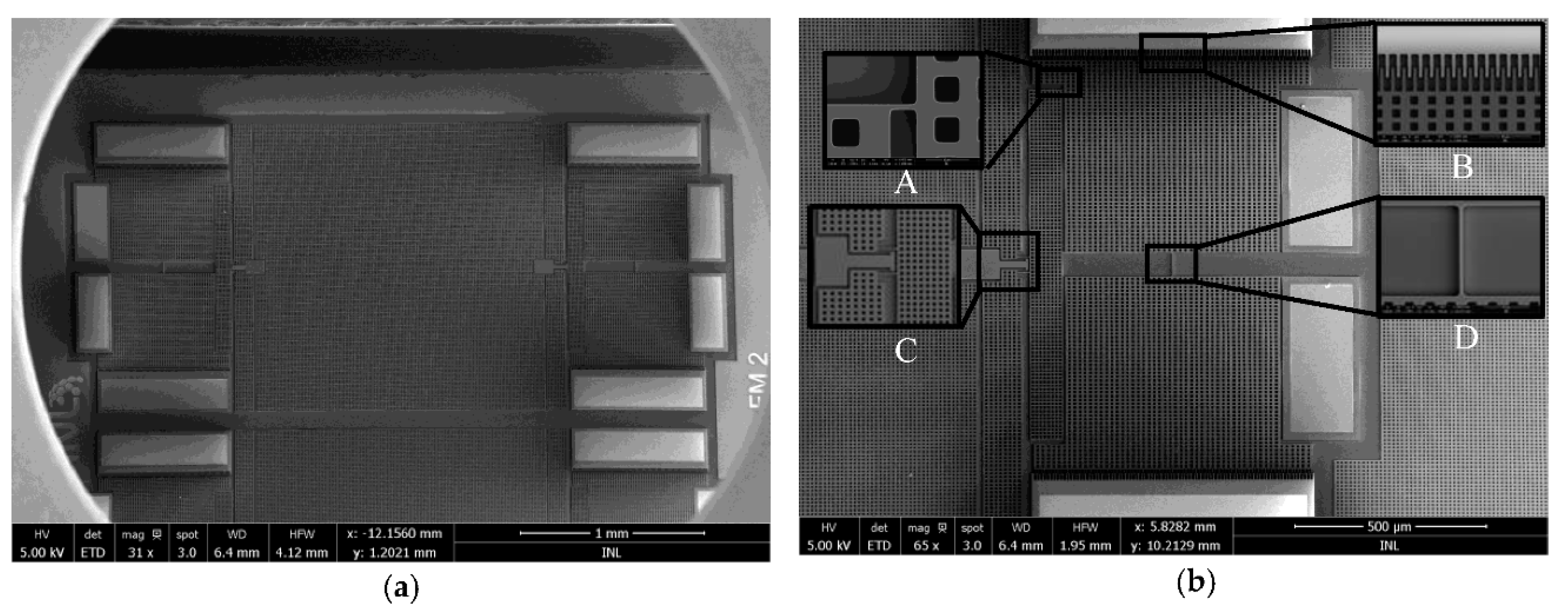
SEM images of the fabricated devices are shown in
Figure 4. The area of an accelerometer die (
Figure 4a) is 4.0 × 1.7 mm
2.
Figure 4b shows an inset of a resonator, highlighting the springs (A) that will change stiffness under stress; the comb-finger actuators (B) for initiation of mass plates movement; the pivot and output beam of the levers (C); and the vibrating connection microbeam (D) (60 × 1.5 µm
2), whose variation in resistance will give a measure of the resonance frequency variation.
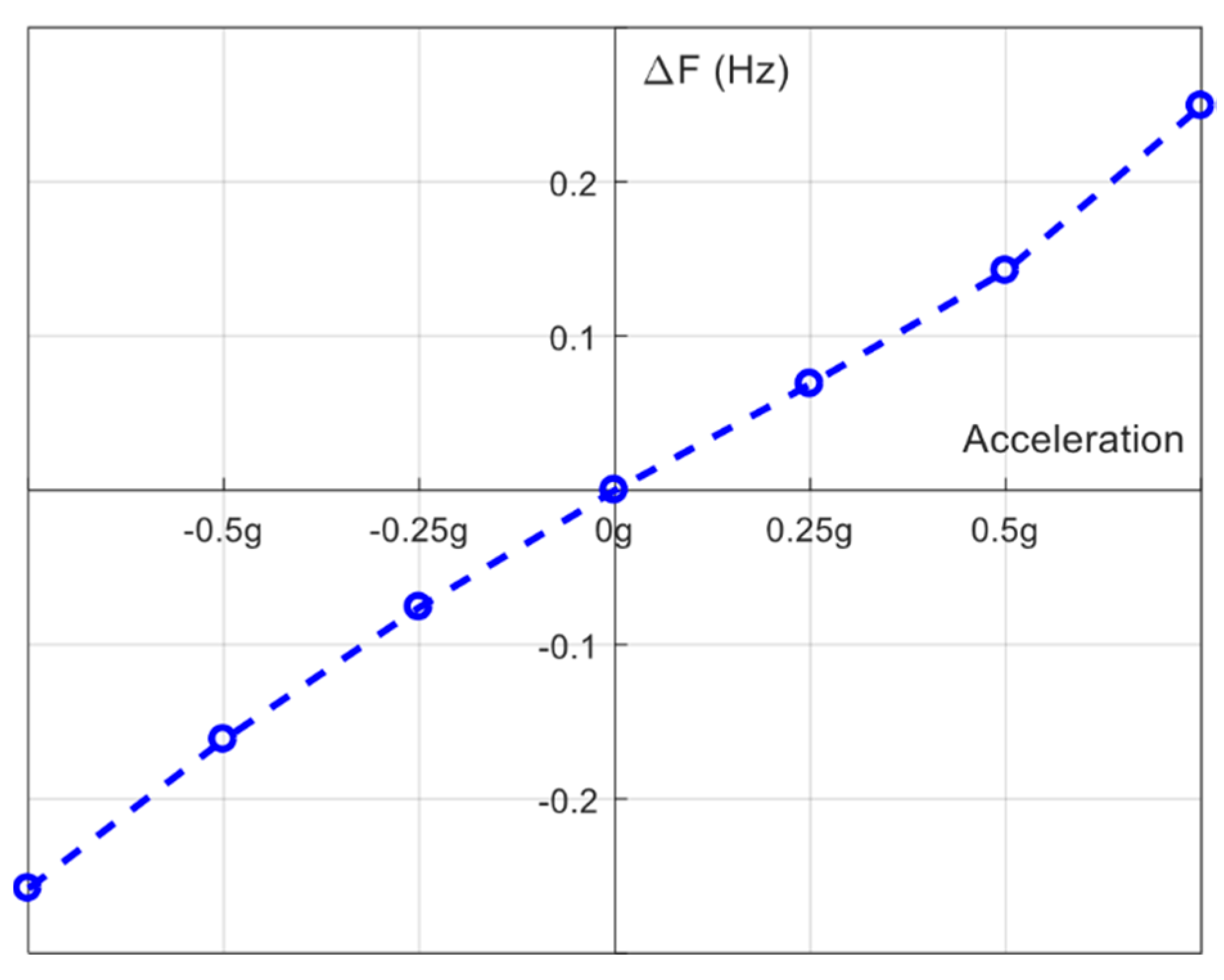
To assess device sensitivity, the variation of resonance frequency of one single resonator was measured, while applying an external acceleration between −1 g to 1 g. The acceleration applied to the device was measured for 0.25 g steps, using a motor capable of rotation. For each applied acceleration, 2000 measures of resonance frequency were performed. A PID control is implemented to update the resonance frequency in runtime. Measurements were performed in vacuum (~5 × 10⁵ mbar) to reduce slide damping.
Fabricated resonators show a high resonance frequency around 705 kHz and a Q-factor close to 20,000 in vacuum, making it suitable for automotive applications. A sensitivity of 0.46 Hz/g (
Figure 5) was measured for a single resonator. Thus, it is expected the accelerometer to have twice the sensitivity when performing differential measurements. Resonance frequency variation is approximately linear in the range of −0.75 g to 0.75 g, as seen in
Figure 5.
5. Conclusions
The FM MEMS accelerometer proposed in this work has a resonance frequency of 705 kHz, well above the range of vehicle vibrations. Theoretically, due to this characteristic, it is expected that the sensor has high immunity to noise, high stability and a large bandwidth. Further characterization tests need to be performed in order to assess these sensor parameters. Also, differential measurements should be completed.
The sensitivity for one single resonator is low (0.46 Hz/g). Although the accelerometer concept is proven, accelerometer sensitivity has to be enhanced. Final characterization of the fabricated accelerometers will allow to perform design improvements, including area reduction, which will be studied, simulated and implemented in order to enhance sensor performance.

